Final Project: Design of an Electric Vehicle
EV MODELLING
Introduction:
Pentration of EVs are increasing day by day in our country. As a concern of increasing fuel price and green protocol, the demand of EVs from the consumer end is also increasing. So the performance of the EV has to meet the consumer needs, for this EV modelling has to be done according to it. By modelling the EV in a MATLAB software the company can have the performnace details of the EV in different conditions of roads like grading, slippery road, wind effect, etc with high efficiency compared to real life. So before building any EV, proper modelling has to be done to find the performance of the EV.
Block diagram of EV:
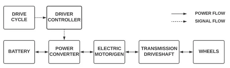
Before discussing about the modelling it is require to know the different components and stages of EV in terms of block diagram. By this we can know about working of EV and thus can model it.
Drive Cycle:
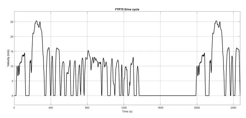
Drive cycle is a pre-input to a vehicle model based on driving speed vs time data of other vehicles in a particular conditions or for a road. Thus knowing the data we can analyse the performance of the EV with that drive cycle and can get best out of it.
The drive cycle taken here is FTP75
Driver controller:
A driver controller is a controlling device which controls the acceleration and decceleration of the vehicle based on the drive cycle input. The acceleration required is taken by +ve `frac(dV)(dt)` and decceleration required is taken as -ve `frac(dV)(dt)`. The control signals generated is send to the PWM generator to create PWM signals for power converter.
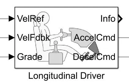
This is a block of driver controller, in this
VelRef is used to give the drive cycle input
VelFdbk is the feedback velocity of the vehicle
Grade is the grade input of the road
AccelCmd is the acceleration command signal send to the PWM signal generator
DecelCmd is the decceleration command signal send to the PWM signal generator
Battery:
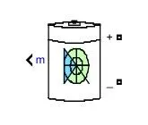
Battery is the power house of the vehicle which stores the energy and dissipates energy when needed. The battery parameter include the nominal voltage, SoC and rated capacity (Ah). The battery performance depends upon these parameters.
Nominal voltage helps in choosing the operating voltage of battery
Rated capacity determines how much ampere can draw in an hour or battery capacity.
SoC (State of Charge) determines the percentage of available charge in the battery.
Power controller:
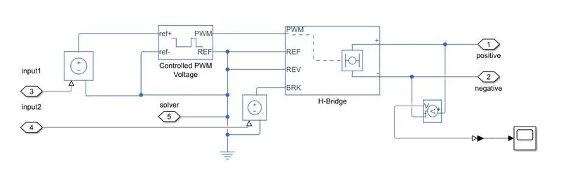
Power controller actually controls the level of the voltage based on the control signal from the vehicle controller. For maximum power the output voltage of the PC (power converter) will be greater than the voltage required for lower power input. The power converter in this model is a H-bridge converter which is also a bidirectional converter means the power can be transferred in both the directions. The PWM generator generates PWM signals which helps in controlling the H-brdige.
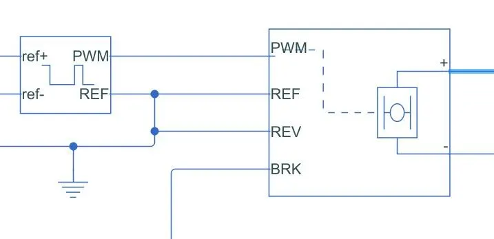
Electric machine:
The electric machine helps in converting the electrical energy into mechanical rotaional energy. The output rotational shaft power depednds upon the input electrical power. By changing the voltage level of the input power the speed of the motor can be changed. The DC motor used here is a permanent magnet motor. The motor selection should be based on the required performance of the vehicle.
If we use high rated motor the vehicle performance increases with reduced range of battery.
If we use low rated motor the vehicle performnace decreases with slightly high range.
So proper selection of motor is required to make vehicle performance and range balanced.
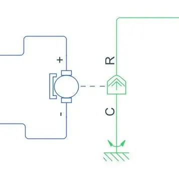
Vehicle body, Transmission Driveshaft and Wheels:
Vehicle body is also taken for modelling, in this different parameters like weight of the vehicle, coefficient of drag, etc are taken. Also this vehicle body model also gives the normal force acting on the front and back wheels. As the values changes with grading of road.
Transmission Driveshaft and wheels are the mechanical rotational parts assosciated with the vehicle. It consist of drivetrains, gears, differential, axles and wheels.
Designing
Step1: Power calculation
From the above block diagram deisgn of EV can be done, for this several parameters are to known.
Vehicle Details:
Total weight of vehicle: 800 kg
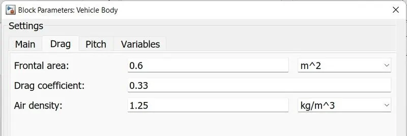
Frontal area: 0.6 `m^2`
Coefficient of drag: 0.33
Air density: 1.25 kg/`m^3`
Radius of tire: 0.3 m
Coefficient of rolling resistance: 0.01
Grading of road (extreme condition) : `20^0`
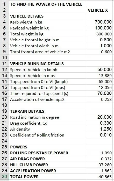
So the total power required is 40.565 kW and we have given input for average speed, when going to extreme we need power more than this so we take motor power as 50 kW.
Hence the motor selection is based on the power required by the vehicle.
Modelling
For modelling we select MATLAB Simulink, in this modelling is done based on the flow diagram discussed above.
1: Vehicle modelling
The vehicle modelling includes selecting the Kerb weight, payload weight, drag coefficient, frontal area, tyre size, tyre friction, sizing, etc. The values given are same as above parameter selection.
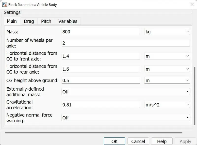
2: Environment modelling
This modelling includes the environmental factors like air density, air velocity, road friction, grading of road, etc. These factors also affects the vehicle performance.
3: Motor modelling
Motor modelling is based on the pre-calculted power power demanded by vehicle as discussed above, the motor modelling is done with its rated voltage, current, frequency (if required) and torque. Thes motor should provide enough power to the vehicle for the required road and drive cycle condition.
Power: 50 kW
Rated voltage: 48 V
Rotor inertia: 0.01 g/cm2
4: Power converter modelling
The power converter is need to designed. A well designed power converter increases the stabilty, reaction time and efficiency of the motor. The power converter needs to power the motor based on the command from driver side.
5: Battery modelling
A battery should be well designed and modelled based on the power requirement by the power converter. The capacity should be properly slected based on the balanced condition of vehicle operating. The battery should also be need to operate based on the SoC, so a proper feedback is required to driver controller and power converter about the SoC of the battery.
Nominal voltage: 80 V
Rated capacity: 100 Ah
6: Driver controller
A driver controller is modelled based on the how the driver is driving, a proper controller is required to model for acceleration and brake input, these values are converter into signals as input to the power converter.
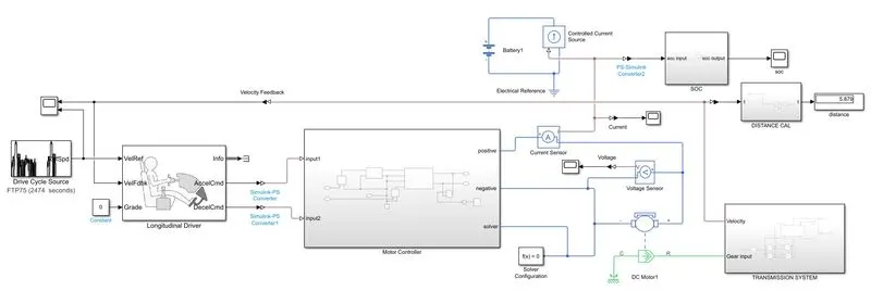
So combining these all models we need to develop a MATLAB Simulink model for the Electric vehicle operation. The matlab model developed is shown below
Simulation Results:
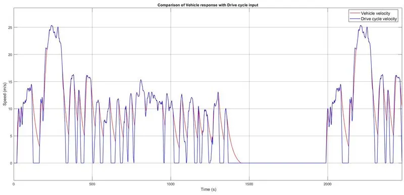
1. Vehicle response with drive cycle input
Observation:
During high acceleration and braking the vehicle response is not as required, this is because the vehicle consist of inertia as the inertia increases the deviation increases. For small response the vehicle response is good.
2. Power converter output
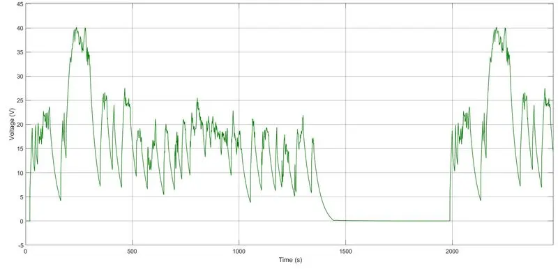
a) Voltage
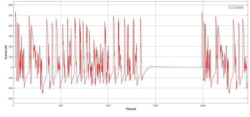
b) Current
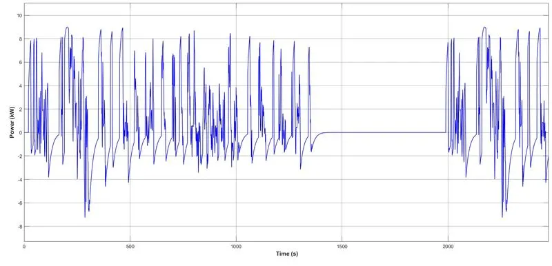
c) Power output
Observation:
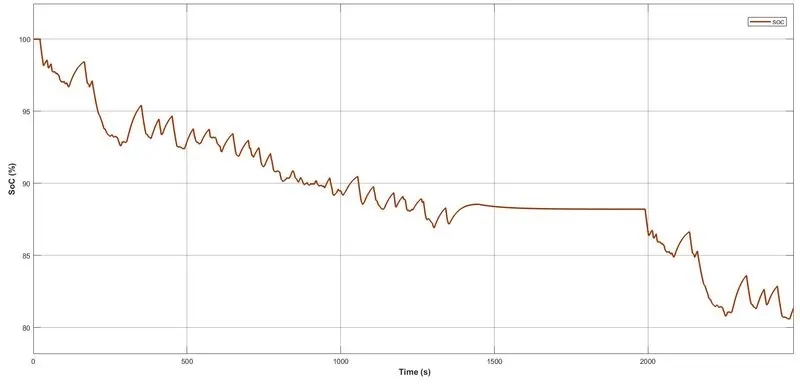
In this it can see that voltage is always positive and current is flowing in both direction and hence the power converter is a two-quadrant operation. During braking the power is fed back to the battery and hence regenerative braking is done. Thus during accelerating the SoC of the battery decreases and during regenerative braking the SoC of battery increases. The SoC of battery is shown below
Conclusion
The modelling of vehicle is done. The stages of modelling are
- Selection of Parameters
- Designing of components
- Modelling
- Analysing the results
The conclusion from the results are
- Power flow in EV has been discussed.
- Vehicle performance has analysed based on the given input.
- Increase in the kerb weight and payload will increase the inertia and hence during sudden acceleration and decceleration the vehicle response shifts from the desired requirement.
- Increase in motor rating increase the vehicle performance in acceleration but decrease in the range of the vehicle.
- Increase in friction braking and regenerative braking, the vehicle response during decceleration increases.
- High efficient power converters helps in increasing the stability, response time and efficiency of the power conversion.
- Increasing in battery capacity increases the weight which will effect vehicle performance due to increased inertia, so battery capacity should be properly selected.
- During retardation regenerative braking is done to convert mechanicla power into electrical power and save in the battery and hence, during regenerative braking the SoC of the battery increases.
- The designing and modelling of EV has done.