Week-11 Challenge: Braking
1. Braking Energy Calculation
The energy required by vehicle to reduce its speed is called braking energy of vehicle. The energy dissipated during braking calculated in terms of Kinetic energy.
Kinetic energy is given by `KE = frac(1)(2)mV^2`
where,
m - mass of the vehicle
V - velocity of vehicle reduced
`V = V_1-V_2`
V1 - initial velocity
V2 - final veocity
Braking energy required for a given drive cycle can be calculated in MATLAB Simulink model as given below.
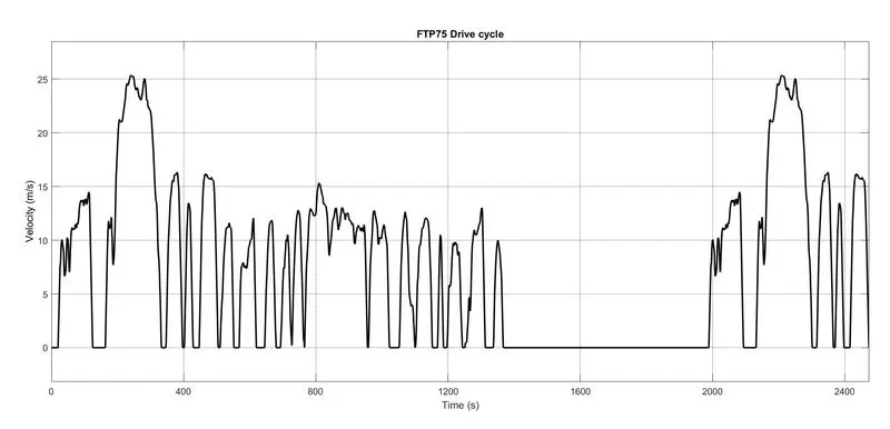
Step 1: Select a drive cycle
In this drive cycle is selected as FTP75
Step 2: Select the area where vehicle is braking for calculation
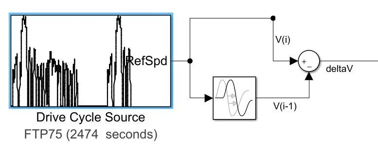
For knowing the braking energy we need to select the area where vehicle is braking, for this we need to know whether vehicle is accelerating or deccelerating. For this we need to find the adjacent speed is increasing or decreasing. This is done by checking
`DeltaV = V(i) - V(i-1)`
If `DeltaV` is -ve then vehicle is deccelerating or braking
If `DeltaV` is +ve then vehicle is accelerating
So we take the area where `DeltaV` is +ve.
For calculating `DeltaV`, the signal is delayed by 1sec and the difference between the original signal (V(i)) and delayed signal (V(i- )) is calculated
Step 3: Distinguish between accelerating energy and braking energy
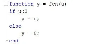
This can be done by sensing `DeltaV` as +ve or -ve, we need braking energy calculation so we take the condition when `DeltaV` is -ve.
The MATLAB function block will help in selecting the signal required
Step 4: Calculating the braking energy
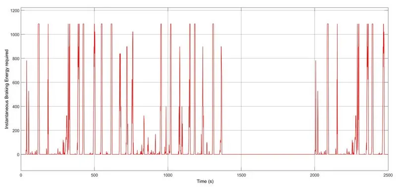
For calculating the braking energy we need to know the vehicle mass (in this m=1000kg). By calculating the kinetic energy braking energy can be calculated.
Braking energy over a time period of 1 sec is, `B.E = 1/2mDeltaV^2`
where, `DeltaV` is velocity difference over a time period of 1 sec.
Step5: Integrate the above data to get total energy
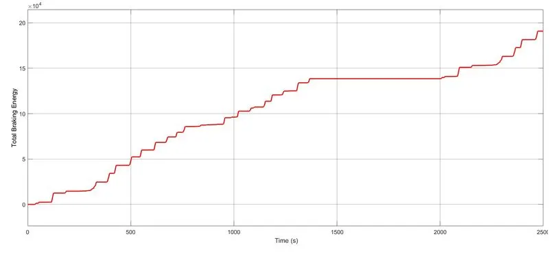
At the end of drive cycle total BE required by vehicle is 190.8kWs or 53Wh.
MATLAB model: https://drive.google.com/file/d/1vtw5kGlRBp1gyZ2w5yStg0Cv97k8EWDR/view?usp=sharing

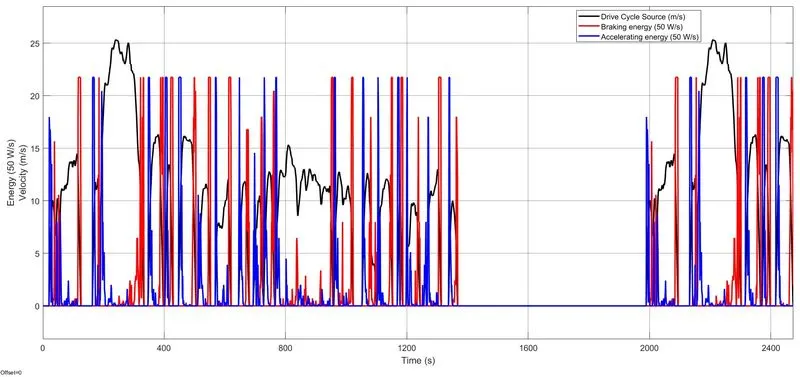
Drive cycle with inst. BE(braking energy) and inst. AE(accelerating energy)
Zoomed portion
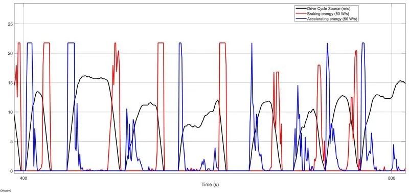
Calculation of braking energy has done.
2. Why braking torque at high speed is low?
For every electric motor (including AC and DC) starting torque is higher compared to torque at near to full speed.
In case of DC motor:
The torque-speed chara of DC motor is given below.
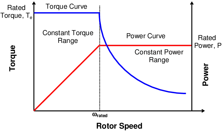
It has two operating region constant torque and constant power, at above rated speed the torque is reduced and is very low at high speeds.
In DC motor the torque is directly proportional to armature current (for SEDC motor).
`T prop I_a` ---------- (1)
The armature current relation is given by
`I_a = frac(V_t - E_b)(r_a)` (motoring condition)
`I_a = frac(E_b - V_t)(r_a)` (braking condition)
where,
`V_t` - terminal voltage
`E_b` - back emf
`r_a` - armature resistance
From the above relation it can seen that armature current is dependent on back emf. Also back emf is directly proportional to the speed of the rotor.
`E_b prop omega_r` -----------(2)
So from the above relation for braking at high speed means beck emf is maximum from (2) (magnitude near to terminal voltage) and thus the armature current is minimum. As from eqn (1), now the torque is low as armature current is minimum.
But during starting the speed is zero implies back emf is zero (from (2)) and thus armature current is maximum at this condition (from(3)), so from (1) the torque is maximum during starting of motor.
Thus electric motor can’t develop braking torque at high speed similar to starting.
In case of AC motor
In case of AC motor the torque-speed chara is given by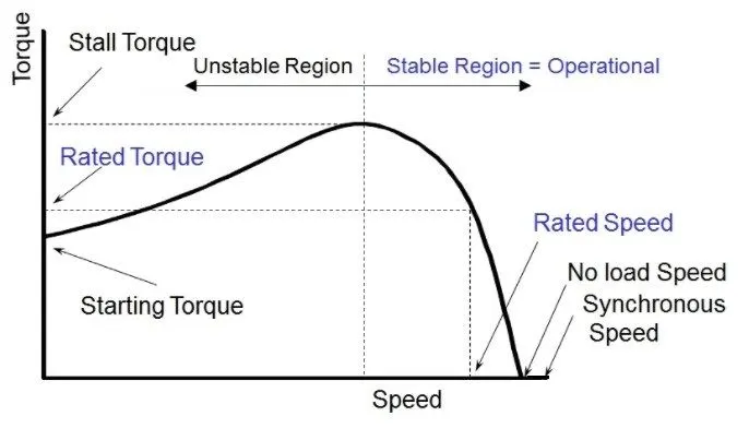
The torque relation is given by
`T = frac(180)( 2 pi N_s) ⋅ frac(( V_1)^ 2)(( R_1 + (R′_2)/s )^2 + j ( X_1 + X'_2)^2)⋅ ( R ′_2)/s`
So at high speed slip is very low and thus torque produced is less. But at starting the slip is maximum (=1) and thus torque is high compared to torque at high speed. Thus electric motor can’t develop braking torque at high speed similar to starting.
How electric and mechanical brakes are coordinated?
There are two methods of electric and mechanical brake coordination
1. Series
2. Parallel
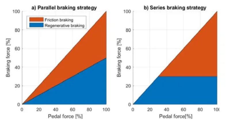
Series Braking:
In series braking, braking is done one after other based on the pedal force. When a low pedal force is applied the vehicle will only allow regenerative braking and if the pedal force increased further the friction braking will be functional for additional braking. Advantage of series braking is when vehicle climbs down hill and vehicle can completly rely on regenerative braking and no loss of braking energy over friction is done.
Parallel Braking:
In parallel braking, braking is done by both regenerative and friction brake together. Advanatges during sudden braking.
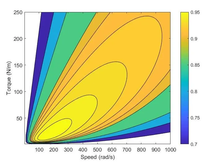
3. Contour mapping of Torque-Speed-Efficiency of an Motor
For efficiency calculation we need to know input power, out power and losses.
Input power = Output power + losses
For a machine the main losses are copper loss, iron loss, windage+friction loss and constant loss.
Copper loss depends upon the current flowinfg through the windings (stator and rotor).
Iron loss depedns upon the magnetization current and is voltage depedent (back emf).
Windage+friction loss depedns upon the speed of the rotor and is proportional to cube of the speed.
Constant losses are constant at any speed and power.
Output power, `P = T.omega`
Thus input power can be obtained by adding outut power + losses.
Copper loss can be expressed in terms of torque as (`T prop I_a`)
Iron loss can be expressed in terms of Speed as (`E_b prop omega`).
The matlab script code for plotting contour of given motor speed, torque and efficiency values is:
x = linspace(1,1000);
y = linspace(1,250);
kc = 0.2; %coefficient for copper loss
ki = 0.008; %coefficient for iron loss
kw = 0.00001; %coefficient for windage loss
cl = 20; %constant loss
[X,Y] = meshgrid(x,y); %converting to matrix form
op = (X.*Y); %output power (Power = Torque*Speed)
a = (Y.^2)*kc; %Copper loss
b = X.*ki; %Iron loss
c = (X.^3)*kw; %Windage loss
ip = op+a+b+c+cl; %input power (= output power + losses)
N = op./ip; %efficiency
V = [0.70, 0.80, 0.85, 0.90, 0.91, 0.92, 0.93, 0.94,0.95];
box off;
grid off;
contourf(X,Y,N,V);
colorbar;
xlabel('Speed (rad/s)'), ylabel('Torque (N/m)'), zlabel('efficiency');
hold on
Output of above code is:
matlab script file: https://drive.google.com/file/d/1UFlczznosw7yRtAynqeZ4MEdt8mVsEmh/view?usp=sharing