Project 1 Mechanical design of battery pack
AIM
Mechanical designing of a 18.5kWh battery pack consisting of Li-ion ANR26650M1-B cells.
OBJECTIVES
The main objectives of this project is to
- Collection of datasheet of ANR26650M1-B Li-ion cells.
- Estimation of no. of cells required for battery pack.
- Designing the battery configuration of modules.
- Designing the battery cell holder for a module.
- Designing the battery pack enclosure and housing.
METHODOLOGY
The project starts from estimating how many no. of cells required for designing a battery pack of 18.5kWh. For this in part I, the datasheet of the cell ANR26650M1-B is discussing and claculation of no. of cells required and the total capacity of all cells is going to estimated. In part II, electrical designing of battery pack with the required battery pack parameter is discussed, it includes calculation of no. of cells required to connect in series and parallel in a battery pack, no. of modules required, module configuration and cell configuration inside the module. In part III, the module packing and BMS support and battery pack enclosure and housing is estimated.
I. ANR26650M1-B
The ANR26650M1-B is the next generation of A123 Systems’ pioneering 26650 cylindrical cell, now with greater power and energy density and lower impedance. This versatile lithium ion cell is suitable for a wide variety of applications and system designs. Proven performance in the toughest conditions, combining durability, reliability, and safety, the ANR26650 cell offers an excellent combination of price-performance.
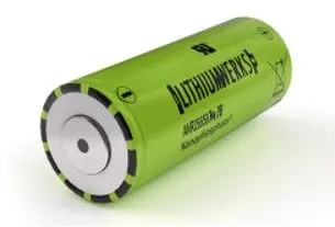
Cylindrical Cell Specifications:
- Cell Dimensions (mm): Ø26 x 65
- Cell Weight (g): 76
- Cell Capacity (nominal/minimum, Ah): 2.5/2.4
- Voltage (nominal, V): 3.3
- Internal Impedance (1kHz AC typical, mΩ): 6
- HPPC 10 Sec Discharge Pulse Power 50% SOC: 200 W
- Recommended Standard Charge Method: 1C to 3.6V CCCV, 45 min
- Recommended Fast Charge Method to 80% SOC: 4C to 3.6V CC, 12 min
- Maximum Continuous Discharge (A): 70
- Maximum Pulse Discharge (10 seconds, A): 120 A
- Cycle Life at 10C Discharge, 100% DOD: >1,000 cycles
- Operating Temperature: -30°C to 55°C
- Storage Temperature: -40°C to 60°C
- Cell capacity in (Wh) = 8.25
Cylindrical Cell Primary Applications:
- Portable high power devices
- Stationary battery backup systems
- Grid stabilization energy storage systems
- Commercial truck and bus hybrid electric vehicles (HEVs)
Lithium Ion Cell Benefits:
- Power: Over 2,600 W/kg and 5,800 W/L
- Safety: Excellent abuse tolerance and environmentally friendly
- Life: Excellent calendar life, 10X cycle life vs. conventional lithium ion
II. ELECTRICAL DESIGNING AND MODELLING
a. Electrical designing of battery pack
The battery pack required parmaters are
| Pack capacity (kWh) | 18.5 |
| Voltage (V) | 99V |
The cell capacity of ANR26650M1-B in Wh for 1 cell is 8.25Wh. From excel calculator we can find the required no. of cells to get a pack capacity of 18.5kWh.
| Capacity required (kWh) | 18.5 |
| No. of cells required (theoretically) | 2242.424242 |
| No. of cells required | 2250 |
| Actual pack capacity (kWh) | 18.5625 |
| No. of series connection | 30 |
| No. of parallel connection | 75 |
| Pack voltage (V) | 99 |
| Pack Capacity in Ah | 187.5 |
- No. of cells required (theoretically) = (pack capacity required)/(capacity of 1 cell) = `frac(18.5 xx 1000)(8.25) = 2242.42`
- So the no. of cells cannot be integer and also capacity may vary with different cells, so we take no. of cells required greater than calculated above.
- So, the actual no. of cells required is 2250 cells.
- The 2250 cells has a total capacity of 18.5625kWh.
- Next we take the pack voltage as it is not given, we take 99V as an assumption value.
- So for getting 99V, the no. of cells connected in series is given by = (pack voltage required)/(1 cell nominal voltage) = `frac(99)(3.3) = 30`
- So the no. of cells need to connected in parallel is = (total no. of cells required)/(no. of cells in series) = 75
- So the pack configuration is 30S75P or 75P30S, any of the configuration can be taken for battery pack.
- But this will be a huge configuration and damge of one cell can cause more time to replace or maintain it.
- So these cells are grouped into another small group consisting of less no. of cells called modules.
- So the battery pack now is a combination of modules.
b. Electrical designing of battery pack modules
The modules consist of group of cells which are connected in required configuration based on design. The modules are connected in series-parallel configuration to form a battery pack.
The excel calculation of the module pack is given as
| No. of cells in each module | 30 |
| No. of modules | 75 |
| Module configuration | 5S15P |
| No. of series connected modules | 5 |
| No. of parallel connected modules | 15 |
- The no. of modules required is calculated based on the no. of cells required in a module.
- No. of modules = (Total no. of cells in battery pack)/(No. of cells in one module) = `frac(2250)(30) = 75`.
- So we require 75 modules in one battery pack, where in each module consist of 30 cells.
- Next we want to calculate the configuration of the modules. Based on the requierd dimension the module configuration id taken.
- The module configuration taken is 5S15P, ie., 5 series combination of 15 parallel connected modules.
Next we need to design the cells in one module. The excel calculation done for finding the configuration of cells in one module is
| No. of cells in each module | 30 |
| No. of modules | 75 |
| No. of series connected modules | 5 |
| No. of parallel connected modules | 15 |
| No. of series connected cells in one module | 6 |
| No. of parallel connected cells in one module | 5 |
| Cell configuration in one module | 6S5P |
| Nominal voltage of module (V) | 19.8 |
| Nominal capacity of module (Ah) | 12.5 |
| Energy capacity of the module (kWh) | 0.2475 |
- The no. of cells required to connected in series in one module is calculated as, = (No. of series connection required in battery pack)/(No. of series connected modules) = `frac(30)(5) = 6`.
- The no. of cells required to connected in parallel in one module is calculated as, = (No. of parallel connection required in battery pack)/(No. of parallel connected modules) = `frac(75)(15) = 5`.
- The configuration of cells in one module is 6S5P, ie., 6 series connection of 5 parallel connected cells.
- The module voltage is, (no. of cells connected in series * individual cell voltage) = 6 * 3.3 = 19.8V.
- Module capacity in Ah is 12.5Ah, and in kWh is 0.2475kWh.
So the electrical designing of the battery pack, pack modules and cells is completed. Thus by the end of designing the electrical parameter of the battery pack are:
- Module configuration: 5S15P
- Battery capacity in kWh = 18.5kWh
- Battery pack voltage = 99V
- Battery pack capacity in Ah = 187.5Ah.
The BMS is connected to each module, the module electrical parameters are:
- Cell configuration: 6S5P
- Module capacity in kWh = 0.2475kWh
- Module voltage = 19.8V
- Module capacity in Ah = 12.5Ah.
In the next part, the mechanical modelling of the battery pack is discussed.
III. MECHANICAL DESIGNING AND MODELLING
In this part all type of mechanical and electrical connections are discussed. From the electrical design part, we have discussed about the configuration of the battery pack, module and cells in module. By this knowledge the mechanical designing is done. The mechanical designing starts from cell to the battery pack.
The cell assembly in the battery pack is shown as below, based on this the battery pack is designed.
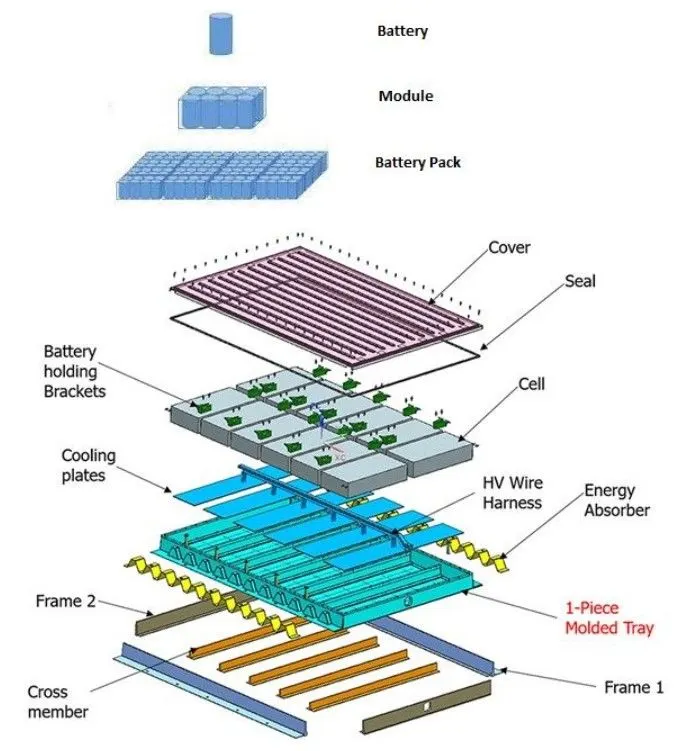
The mechanical design starts from the cell to complete battery pack.
1. Cell Holder
In the module the cells has to be placed in a order, the order is based on the cell configuration in a module, ie. 6S5P. For this cell holder are required of 6S5P or 6x5 configuration.
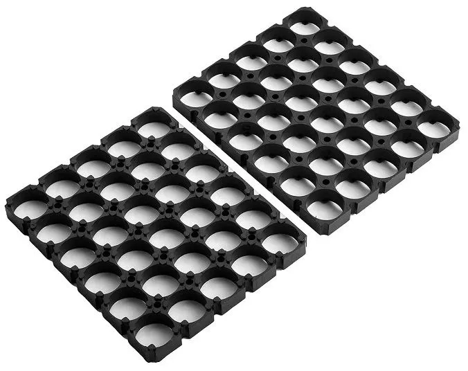
The functions of battery holder are:
- Keep cells fixed in place safely and securely while conveying power from the batteries to the device.
- Mechanical and vibration protection.
- Keeps a minimum distnace between cells for ventilation and thermal expansion.
- Helps in easy electrical connection between cells
The cells are then joint in the battery holder, and the battery with the holder will look like as below
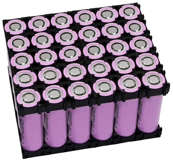
Thus mechanical holding of the cells in the module is completed.
2. Connection of cells in module
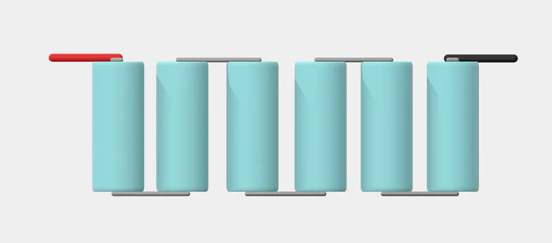
The configuration of cells in 1 module is 6S5P. The connection is made by connecting the 5 sets of 6 parallel electrically connected cells in series. There are many types of electrical connections between the cells based on the type of material and mode of connection. In this nickel strips are used to join the cells series and parallel.
The Nickel strips are available in strip and plate.
The strip type nickel

The plate type nickel strip

The plate type nickel strip is usde here for the electrical connection between the cells.
The nicekl strips are joined to cell by
- Soldering
- Spot welding
By using spot welding the Nickel strip are joint over the cells to form a battery module. Spot welding works by applying pressure and heat to the weld area using copper alloy electrodes. These electrodes transport an electrical current through the weld segments. As the material melts the parts are fused. At this point, the current is turned off and pressure from the electrodes is upheld.
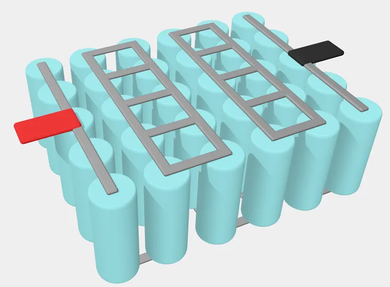
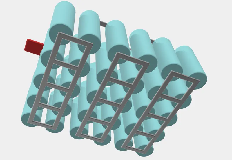
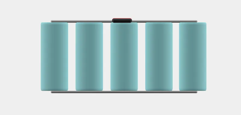
The final form of cell configuration with only electrical connections are
Top view
Bottom view
Side view (series connection)
Side view (parallel connection)
The final mechanical model of cells in module with casing and electrical connection.
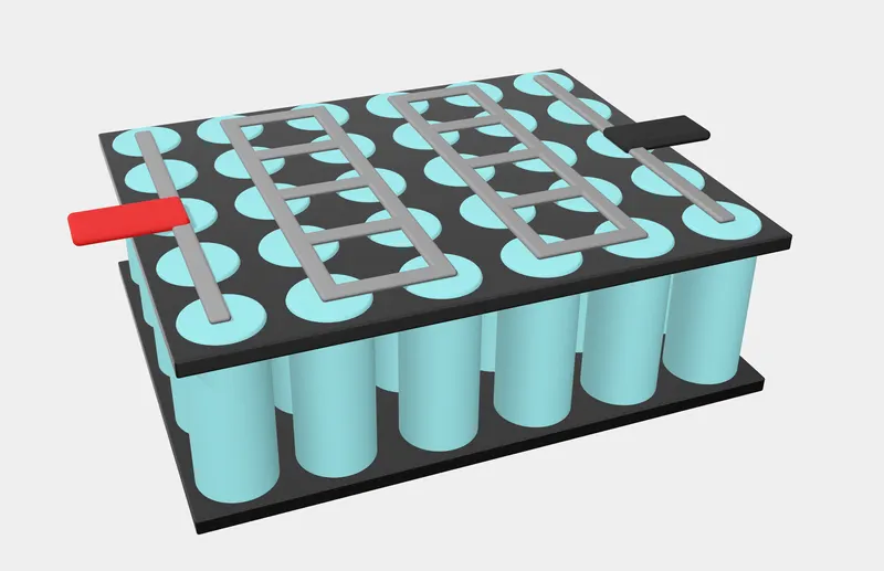
The above sample pictures are taken from 3D model, the 3D model file is attached with this project.
The size of the cells with cell holder will be
| Module casing size | 6S5P |
| Width of one holder for one cell (mm) | 30 |
| Length of one holder for one cell (mm) | 30 |
| Module width (mm) | 180 |
| Module length (mm) | 150 |
| Module height (mm) | 70 |
3. Module casing
As the cells are connected with each other to form a module, now these cells are required to housed in a module casing.
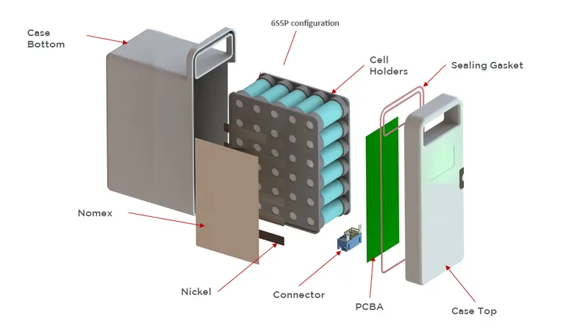
The case consist of
- PCBA: PCB for making the electrical connections and if required module level BMS can be included.
- Connectors: For making electrical connection with external DC bus or circuits.
- Nomex: type of material for thermal isolation or act as a flame resistant, included for safety.
- Casing: casing can be of metal type or plastic type based on the reqirement, metal type is most commonly used to collect heat or can be usde with the cooling system for battery.
The final form of module is as shown below
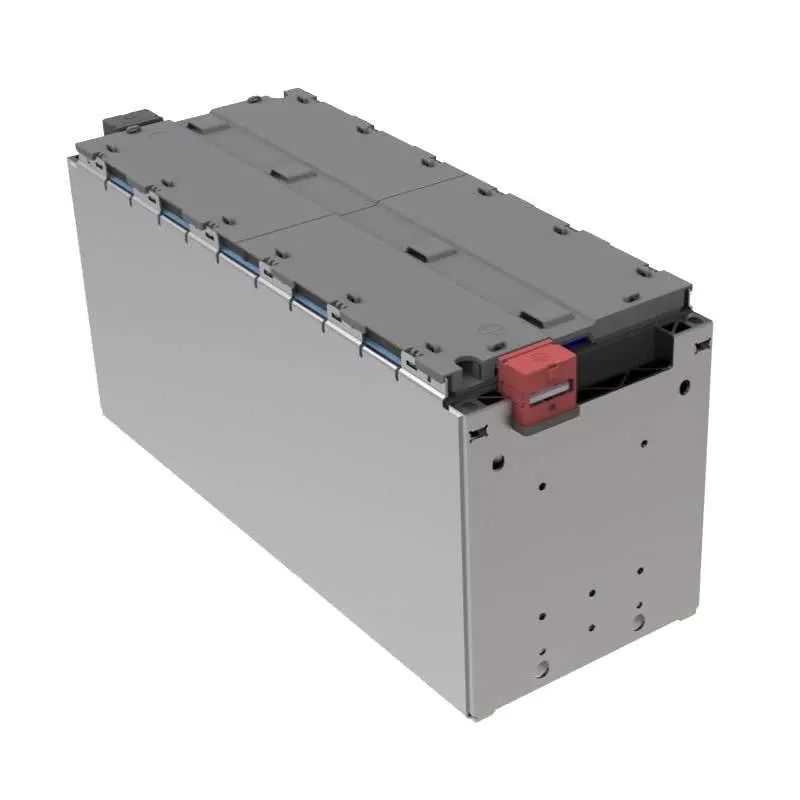
The module level mechanical designing is over, now the battery pack design is required.
4. Battery pack design
This is the final design, the design is based on the area availability and the type of requirement.
For EV application, the flatbed type is required and for solar or BESS, a box type is required.
In this project of 18.5kWh the battery pack is needed for EV application.
The EV application the battery packs are having a bed shape configuration. It means the height of battery pack is kept minimum and the length and breadth (lesser than length) has more, so the shape look like bed.
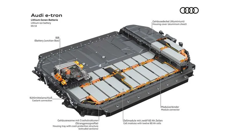
The battery pack houses all the modules and also have BMS, cooling system and DC bus with neccessary mechanical and thermal protection. The EV battery pack assembly of Audi e-tron EV look like as shown below
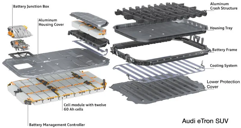
The above battery pack consist of
- Lower protection cover: This cover helps in mechanical protection and act as base for housing the modules.
- Cooling system: It consist of a liquid cooling system and a flat fins through which the coolant flows to collect heat generated in the module. There is two pipes on either side, one act as input to coolant and other act as output to coolant. These coolant are cooled in external radiator.
- Battery frame: It covers the side and act as a barrier between the battery pack and other components, it also gives mechanical protection to the battery pack against any external forces acting on the battery pack. This is made up of steel.
- Housing tray: The housing tray act as a rest for battery modules, it is laid over the cooling system and the battery modules are kept over it.
- Aluminium crash structure: This is to create housing space for individual modules, sometimes housing tray and crash structure are combined together. This frame is made up of aluminium.
- Battery modules: The battery modules are inserted in the crashing structure, and afterwards neccessary electrical connections are made based on the configuration.
- Aluminium housing cover: This is the upper most covering done over the battery pack. All the connections between the mechanical structures are made by screws and nuts.
- If the modules are arranged one layer above, then above sequence of mechanical assembly is made.
- The electrical connections and sensor connections are made with BMS attached to the battery pack, the battery pack also consist of electrical protection circuits like fuses are also included.
- The battery junction box acts a hub for electrical connections and sensor connections.
The final connection of EV battery pack (above example) is as shown below.
Thus the final battery pack is designed for EV. Similar drawing is made in 3D software for above project of 18.5kWh, with 5S15P module configuration battery pack is shown below.
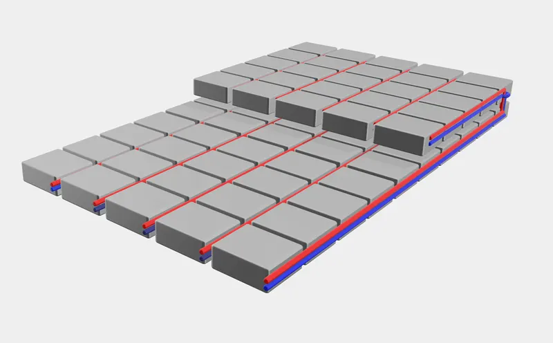
In this battery pack is designed in two layer, first layer consist of 10x5 module and second layer consist of 5x5 modules. The 15 modules are connected in parallel as shown in figure and these 15 parallel modules are connected in series, this connection is done with the help of battery junction box.
The 3D model with housing, cooling system and BMS is also modelled, the image of the 3D model is as shown below
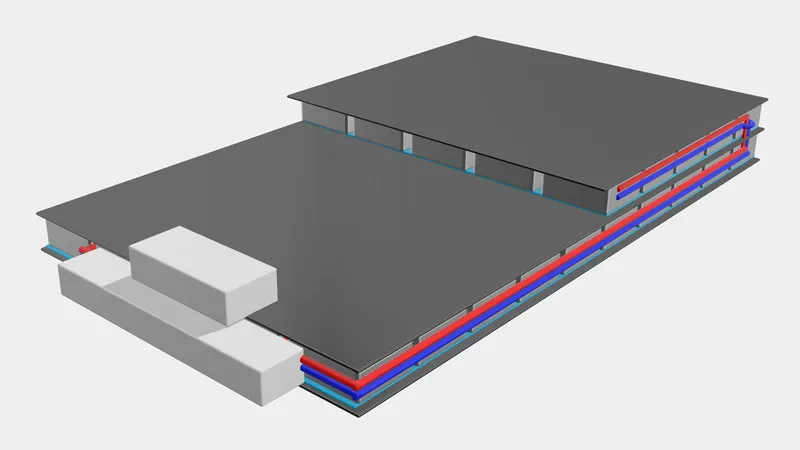
The estimated overall length, breadth and height of the frst layer is
- Length: 2.0m
- Width: 1.2m
- Height: 15cm
Including the second layer, the length and breadth remain same, the height at second layer increase to 25cm.
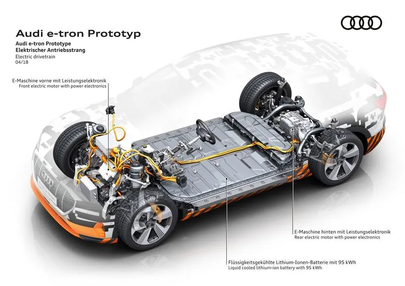
The final image of car with battery pack would be as shown below.
CONCLUSION
The 18.25kWh battery pack for EV has designed electrically and mechanically, considering all safety and performance aspects. The battery pack consist of 5S15P configuration of module and each module consist of 6S5P cell configuration. So, the combined performance of the battery pack is calculated with the help of excel calculator, the parameter of the battery pack is
- Total capacity: 18.5kWh
- Nominal voltage: 99V
- Nominal capacity: 187.5Ah
The mechanical design was studied and modelled under with the reference of Audi e-tron EV battery pack.
3D model of cell configuration and module configuration has done with the help of 'Vectary', and the layout of the module aslo shown with the help of 3D model.