Project 1 (Mini Project on Vehicle Direction Detection
AIM
Creating a simulink model for Vehicle Direction Detection ADAS feature for vehicle.
INTRODUCTION
identifying the direction of the vehicle is one of the important & diverse features in Autonomous driving & Advanced Driver Assistance Features. This particular sub-feature of identifying the direction of vehicle is basically identifying the direction the vehicle is taking based on the camera input.
Camera reads the road signs & stores into its memory with unique values for left turn, right turn & straight drive. Depending on the direction it is taking, final indication is given to the driver – as an indication if he is driving in the recommended direction or not.
Vehicle Direction Determination can also be coupled along - side features like GPS systems to identify whether the vehicle is reaching its destination in an optimized manner. This sub feature can also be used along with Lane Detection, Highway Warning, Ramp Entry / Exit in Wrong Way Detection etc.
OBJECTIVES
- Development of MATLAB Simulink model as per requirement.
- Tag the requirements to the simulink model; tagging requirement 1 & requirement 2 to their corresponding subsystems is fine.
- MBD compliant changes, Data Dictionary creation & code generation of the model.
METHODOLOGY
The Vehicle Direction Detection is modelled MATLAB Simulink with required data. The modelling steps include
- Collection of requirement for the model.
- Building the MATLAB Simulink model.
- Building the SLDD file for the model.
- Validating the model with model advisor tool.
- Code creation.
I. REQUIREMENTS
Requirement - 1:
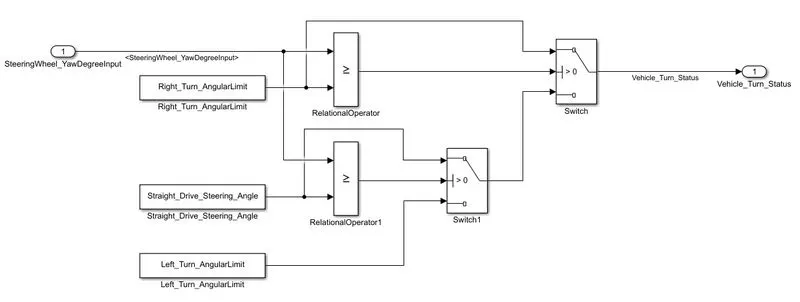
- Steering wheel input as yaw rate (Signal name: SteeringWheel_YawDegreeInput) is the input for this system.
- This is compared against 3 angular values, one each for left turn, right turn & straight drive (Calibration Values: Right_Turn_AngularLimit, Left_Turn_AngularLimit, Straight_Drive_Steering_Angle) to say which specific direction the steering wheel is turning towards.
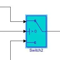
- Use switch blocks to compare & develop this requirement. Keep this requirement in a subsystem & output of this requirement is a local signal (Signal Name: Vehicle_Turn_Status).
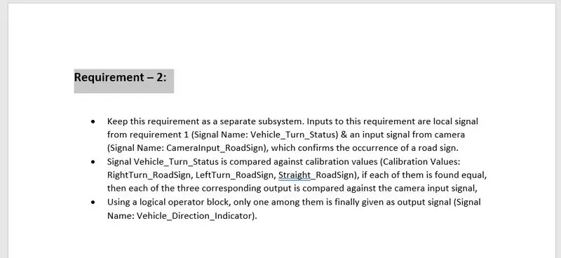
Requirement – 2:
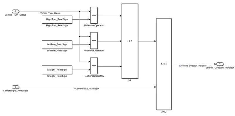
- Keep this requirement as a separate subsystem. Inputs to this requirement are local signal from requirement 1 (Signal Name: Vehicle_Turn_Status) & an input signal from camera (Signal Name: CameraInput_RoadSign), which confirms the occurrence of a road sign.
- Signal Vehicle_Turn_Status is compared against calibration values (Calibration Values: RightTurn_RoadSign, LeftTurn_RoadSign, Straight_RoadSign), if each of them is found equal, then each of the three corresponding output is compared against the camera input signal,
- Using a logical operator block, only one among them is finally given as output signal (Signal Name: Vehicle_Direction_Indicator).
II. MODELLING
From the above requirement the MATLAB Simulink model is build, the Modelling part includes
- Creating the required Simulink model
- Linking the document with the subsytem
- Creating SLDD file for signals and constants
- Model Configuration setting
Simulink Model:
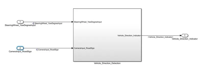
1. Main window
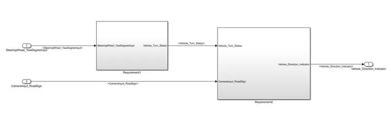
2. Inside the main subsytem, consist of two subsytem requirement1 and requiremen2.
2.a. Requirement1
2.b. Requirement2
Tagging the requirement documents to the respective subsystem
Follow the steps to tag the required document to the subsystem
- Create the requirement document in word or pdf format in same folder that of model file.
- Select the heading of the requirement document.
- Now open the MATALAB Simulink model.
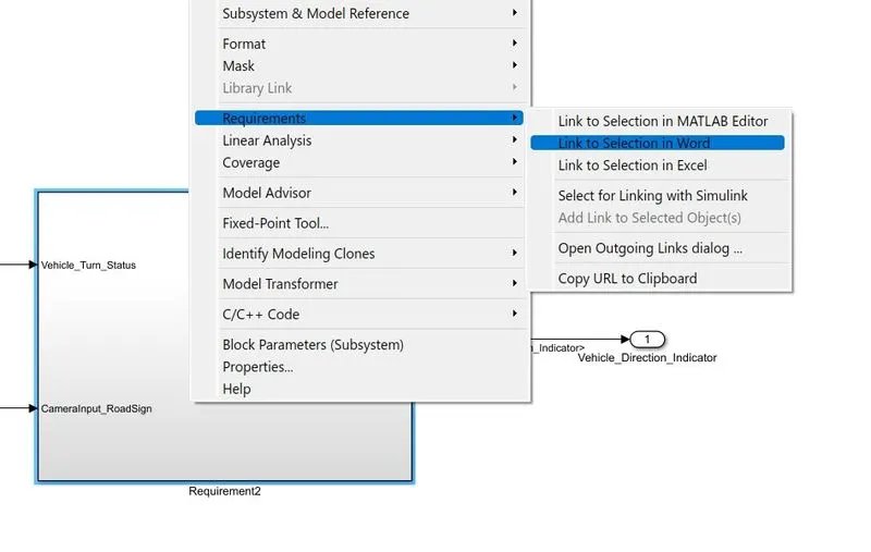
- Right click on the required subsytem. select 'Requirements' and the select 'link to Selection in Word' (for doc file)
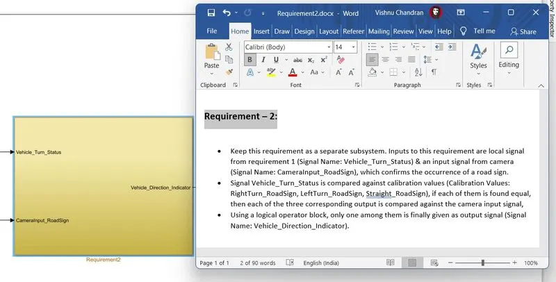
- Now again right click on the susbsystem and check whether the required document is linked or not, and the select the "Requirement-1' now the document will open in side window,
- repeat the same for Linking document with other subsytem block.
Creating SLDD file
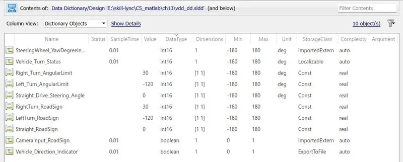
The SLDD file is neccessary to know about the signal parameter and constant parameter. For creating the SLDD file for the above model follow the steps
- Open the Model Explorer (Ctrl+M)
- Create an External Data file for above model as "vdd_dd.sldd" and save it in same folder as that of model file.
- Add signals and constants based on the data
- Right click on the vdd_dd after entering all the datas and select 'Save changes' and click on Ok.
- Close the model explorer and refresh the model file.
- Now the all signals and constants will be updated.
Model Configuration
In model settings under 'Solver' change the following parameters
- Type: Fixed-step
- Solver: discrete (no continous states)
- Fixed-step size: 0.01s
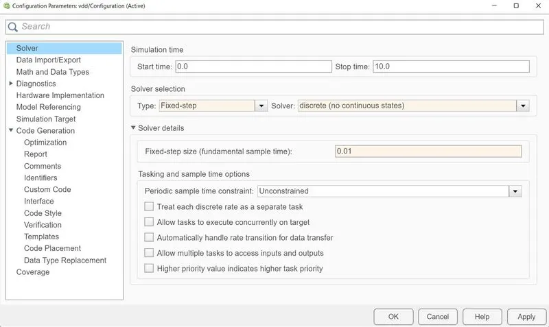
After changing click on 'Apply' and the 'OK'.
II. MODEL ADVISOR
Model Advisor tool is used to check whether the following model works properly and build properly according to many standars selected.
For checking the model with Model Advisor tool follow the steps
- Open Model Advisor tool
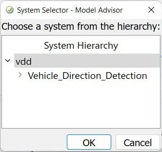
- A window will pop up, select whole system with name of the file
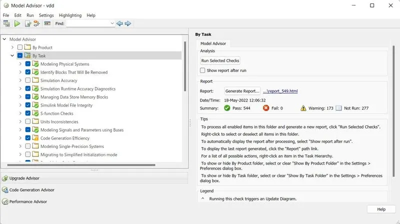
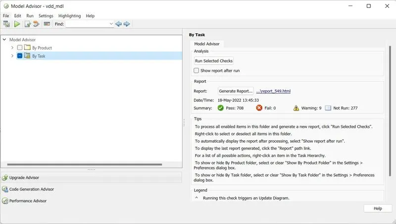
- Now Model Advisor window will be open, in that select "By Task", in under that select the required standars for testing.
- Now click on the "Run Selected checks"
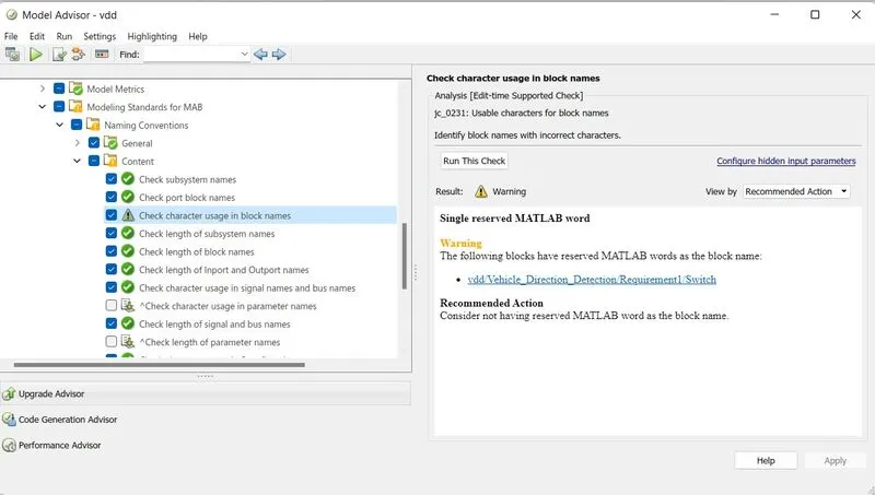
- After running in the window as shown above there will be warning message will be shown.
- To coorect the warning message
- Select the standard in which warning message is shown
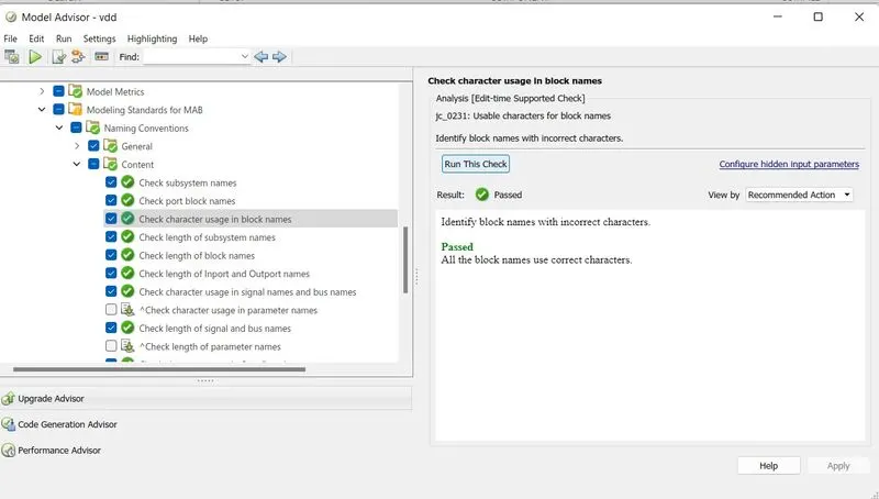
- Selevct the warning message, it will automatically divert to the area where warning is shown
- Change the name (in this case) and save the model and go back to the Model Advisor window
- Click on "Run this check", if the problem is solved that part will be shown with a greean tick
- Select the standard in which warning message is shown
- Continue above steps for all warnings, and try to resolve as many as warnings.
- In this at last 9 warnings remains, earlier it was 173 which is reduced to 9, which is acceptable.
- Now the model has followed most of the standard and is now ready for code generation.
- If required "Report" can be generated for Model advisor tool.
III. CODE GENERATION
The code generation is required to convert the model into a c file for machine level programming, with the help of MATLAB the c file can be generated.
For Code generation follow the steps
- Open the model settings in that under Code generation change the following parameters
- System target file: grt.tlc
- Language: C
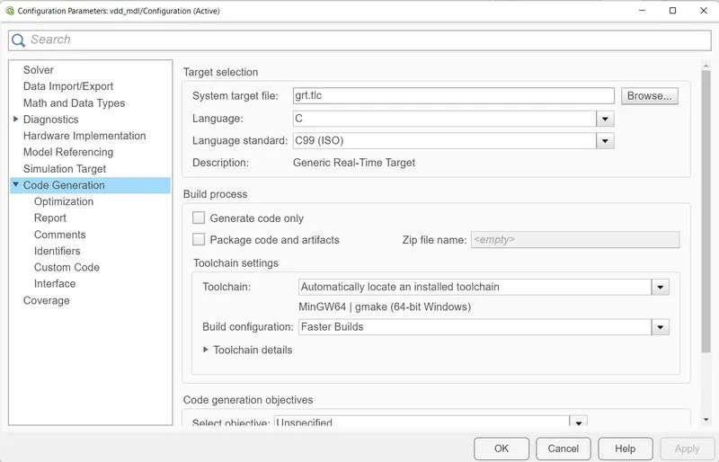
- Click on Apply after changing the datas.
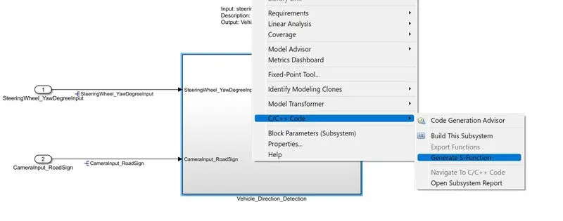
- Now go back to the model, right click on the main subsytem, select C/C++ code and then select generate s-function
- A new window will appear select "Create SIL block"
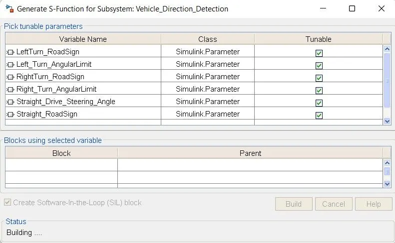
- Now click on Build
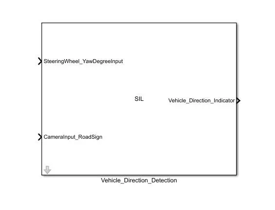
- A new MATALAB Simulink window will open with SIL block of the model for SIL testing
- Also in the folder containing MATLAB file a new folder "Vehicle_Direction_Detection_ert_rtw" will be reated along with SIL.
- The folder consist of generated C file and h file.
- The generated C code of main subsytem is
-
/*
 * Academic License - for use in teaching, academic research, and meeting
 * course requirements at degree granting institutions only.  Not for
 * government, commercial, or other organizational use.
 *
 * File: Vehicle_Direction_Detection.c
 *
 * Code generated for Simulink model 'Vehicle_Direction_Detection'.
 *
 * Model version                  : 1.27
 * Simulink Coder version         : 9.6 (R2021b) 14-May-2021
 * C/C++ source code generated on : Wed May 18 14:41:09 2022
 *
 * Target selection: ert.tlc
 * Embedded hardware selection: Intel->x86-64 (Windows64)
 * Code generation objectives: Unspecified
 * Validation result: Not run
 */

#include "Vehicle_Direction_Detection.h"
#include "Vehicle_Direction_Detection_private.h"

/* Exported data definition */

/* Definition for custom storage class: ExportToFile */
boolean_T Vehicle_Direction_Indicator; /* '<S3>/AND1' */

/* Const memory section */
/* Definition for custom storage class: Const */
const int16_T LeftTurn_RoadSign = -120;
                                   /* Referenced by: '<S3>/LeftTurn_RoadSign' */
const int16_T Left_Turn_AngularLimit = -120;
                              /* Referenced by: '<S2>/Left_Turn_AngularLimit' */
const int16_T RightTurn_RoadSign = 30;
                                  /* Referenced by: '<S3>/RightTurn_RoadSign' */
const int16_T Right_Turn_AngularLimit = 30;
                             /* Referenced by: '<S2>/Right_Turn_AngularLimit' */
const int16_T Straight_Drive_Steering_Angle = 0;
                       /* Referenced by: '<S2>/Straight_Drive_Steering_Angle' */
const int16_T Straight_RoadSign = 0;
                                   /* Referenced by: '<S3>/Straight_RoadSign' */

/* Real-time model */
static RT_MODEL_Vehicle_Direction_De_T Vehicle_Direction_Detection_M_;
RT_MODEL_Vehicle_Direction_De_T *const Vehicle_Direction_Detection_M =
  &Vehicle_Direction_Detection_M_;

/* Model step function */
void Vehicle_Direction_Detection_step(void)
{
  /* local block i/o variables */
  int16_T Vehicle_Turn_Status;

  /* Switch: '<S2>/task1' incorporates:
   *  Constant: '<S2>/Right_Turn_AngularLimit'
   *  Constant: '<S2>/Straight_Drive_Steering_Angle'
   *  Inport: '<Root>/SteeringWheel_YawDegreeInput'
   *  RelationalOperator: '<S2>/RelationalOperator1'
   *  RelationalOperator: '<S2>/RelationalOperator2'
   *  Switch: '<S2>/Switch1'
   */
  if (SteeringWheel_YawDegreeInput >= Right_Turn_AngularLimit) {
    /* Switch: '<S2>/task1' */
    Vehicle_Turn_Status = Right_Turn_AngularLimit;
  } else if (SteeringWheel_YawDegreeInput >= Straight_Drive_Steering_Angle) {
    /* Switch: '<S2>/Switch1' incorporates:
     *  Constant: '<S2>/Straight_Drive_Steering_Angle'
     *  Switch: '<S2>/task1'
     */
    Vehicle_Turn_Status = Straight_Drive_Steering_Angle;
  } else {
    /* Switch: '<S2>/task1' incorporates:
     *  Constant: '<S2>/Left_Turn_AngularLimit'
     *  Switch: '<S2>/Switch1'
     */
    Vehicle_Turn_Status = Left_Turn_AngularLimit;
  }

  /* End of Switch: '<S2>/task1' */

  /* Logic: '<S3>/AND1' incorporates:
   *  Constant: '<S3>/LeftTurn_RoadSign'
   *  Constant: '<S3>/RightTurn_RoadSign'
   *  Constant: '<S3>/Straight_RoadSign'
   *  Inport: '<Root>/CameraInput_RoadSign'
   *  Logic: '<S3>/OR1'
   *  RelationalOperator: '<S3>/RelationalOperator1'
   *  RelationalOperator: '<S3>/RelationalOperator2'
   *  RelationalOperator: '<S3>/RelationalOperator3'
   */
  Vehicle_Direction_Indicator = (((Vehicle_Turn_Status == RightTurn_RoadSign) ||
    (Vehicle_Turn_Status == LeftTurn_RoadSign) || (Vehicle_Turn_Status ==
    Straight_RoadSign)) && CameraInput_RoadSign);
}

/* Model initialize function */
void Vehicle_Direction_Detection_initialize(void)
{
  /* (no initialization code required) */
}

/* Model terminate function */
void Vehicle_Direction_Detection_terminate(void)
{
  /* (no terminate code required) */
}

/*
 * File trailer for generated code.
 *
 * [EOF]
 */
-
CONCLUSION
The Vehicle Direction Detection model has created using the MATLAB Simulink. The neccessary SLDD file is created for all the signals and variables used in the model. The model is then tested with MATLAB ADVISOR tool and lastlty the C-code is generated along with the SIL block of the model.
All the files including
MATALAB model file: vdd_mdl.slx
SLDD file: vdd_dd.sldd
Linked Documents: Requirement1.docx and Requirement2.docx
SIL block model: vdd_sil.slx
And the c-file: Vehicle_Direction_Detection.c
is attached with this.