Project 2
HYBRID FUEL CELL ELCTRIC VEHICLE MODELLING WITH BATTERY AND ULTRACAPACITOR
AIM
To model a hybrid electric fuel cell electric vehicle modelling with secondary storage consisting battery and ultracapacitor.
INTRODUCTION
Fuel cell electric vehicles (FCEVs) are powered by hydrogen. They are more efficient than conventional internal combustion engine vehicles and produce no tailpipe emissions, they only emit water vapor and warm air. FCEVs use a propulsion system similar to that of electric vehicles, where energy stored as hydrogen is converted to electricity by the fuel cell. Unlike conventional internal combustion engine vehicles, these vehicles produce no harmful tailpipe emissions. FCEVs are fueled with pure hydrogen gas stored in a tank on the vehicle. Similar to conventional internal combustion engine vehicles, they can fuel in less than 4 minutes and have a driving range over 300 miles. FCEVs are equipped with other advanced technologies to increase efficiency, such as regenerative braking systems that capture the energy lost during braking and store it in a battery and UC (ultracapacitor).
A hybrid FCEV consist of Battery and UC due to its different power density and energy density characteristics. The UC has highest power density but have lowest energy density, in FC it have highest energy density but lowest power density and the battery have moderate power and energy density among three. By taking advantages of each, the dynamic power demand of the vehicle can be achieved with these three sources.
A well developed EMS (Energy Management System) is required to manage these three power sources on the basis of safe operating condition, power distribution, healthy operation etc.
The amount of power required by the vehicle is determined by the vehicle body model, in which it calculates the overall dynamic power required by the vehicle to move according to the signal come from driver control unit.
This project focus on building a complete hybrid FCEV model for analysing the fuel, power, range of the vehicle for a particular driving cycle.
OBJECTIVE
- Mathematical modelling of Fuel cell.
- Mathematical modelling of Battery.
- Mathematical modelling of Ultracapacitor.
- Developing algorithm for EMS (energy management system).
- Vehicle body modelling.
- Modelling of driver control unit.
METHODOLOGY
There are two approches for EV modelling forward and backward. In this project backward approach is cosidered. It is also called either the wheel-to-engine or front-to-rear method. In this type of method, no model of the behaviour of driver is required. The force required to accelerate the vehicle is determined from a velocity/drive cycle. This force is convereted to power, and the total power is calculated required by the engine. From this calculted power, energy requirement is calculated. from this data the rating of the Fuel cell, Battery and UC are selected. Atlast based on the requiremtn the modelling of each part is done and then integrated for complete performance analysis.
I. VEHICLE BODY MODELLING
The vehicle body modelling consists of different force acting on the vehicle it includes
- Air drag force
- Rolling resistance force
- Acceleration force
- Hill climb force
These forces are calculated based on the mathemeatical relation. The mathematical relation of each force are
The model also calculates the various force like
- Rolling resistance force: force due to friction between the tire and road
- `F_(rr) = mu.M.g.cos(alpha)`
- Air drag: force due to air density and wind speed + vehicle speed (V)
- `F_(ad)=frac(1)(2).rho.A_(f).C_(d).V^(2)`
- Grade: The force due to grade of road and mass of the vehicle
- `F_(g) = M.g.sin(alpha)`
- Acceleration force: Due to mass and inertia of the vehicle
- `F_(a) = M.frac(dV)(dt)`
The above model is modelled in the simulink
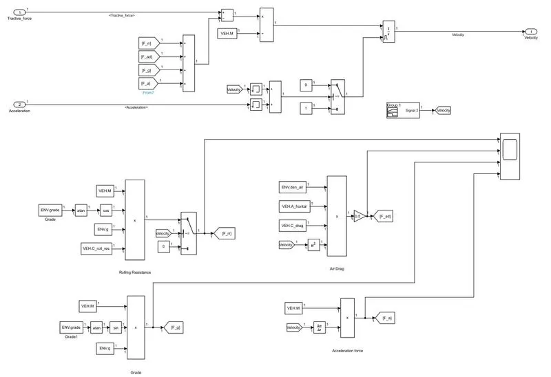
The model input consist of traction force and acceleration command, the traction force is the force which comes from the electric machine used to drive the vehicle, this force is subtracted from the forces acting on the vehicle to get the resulting force. Which on dividing with mass of vehicle gives acceleration on integrating the acceleration actual velocity of the vehicle is obtained.
II. POWERTRAIN MODELLING
The powertrain includes the system which participate in powering the vehicle.
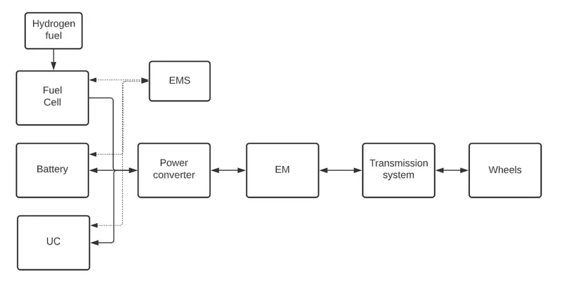
The powertrain of a Fuel cell EV is modelled in simulink as shown below
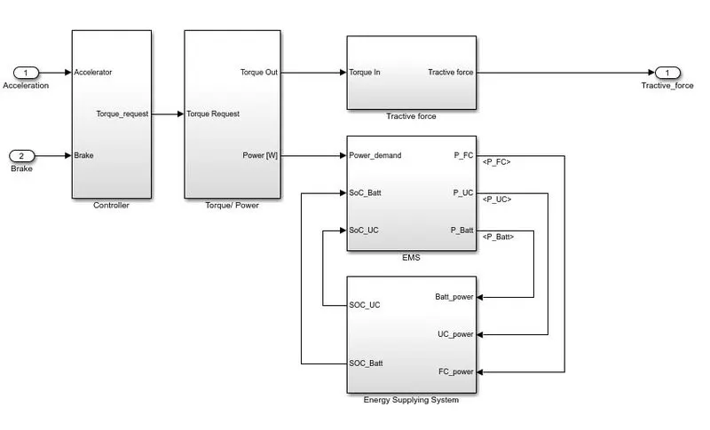
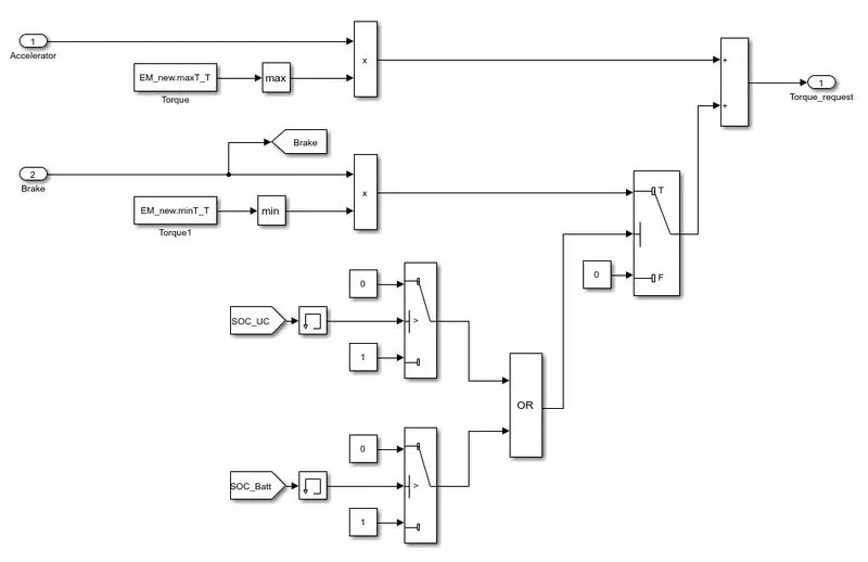
The controller gives the control signals based on the driver input, so that the ECU can generate the required power to drive the vehicle.
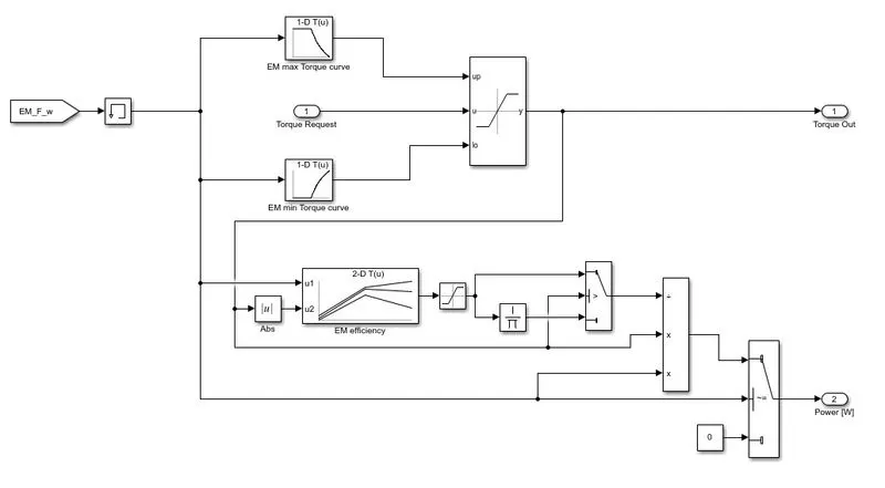
The required torque request is send to the EM, so that it can generate the required power to drive the vehicle. The Engine power is met by the Energy supplying device like Fuel cell, Battery and UC. The power is shared based on the control signals from the EMS.
The engine model is given as
The Energy supllying devices are
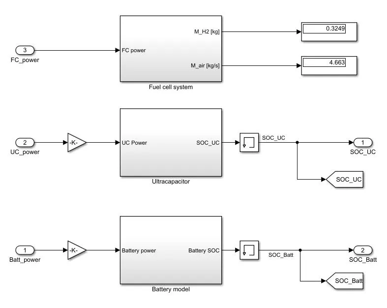
1. Fuel cell
Fuel cells work like batteries, but they do not run down or need recharging. They produce electricity and heat as long as fuel is supplied. A fuel cell consists of two electrodes—a negative electrode (or anode) and a positive electrode (or cathode)—sandwiched around an electrolyte. A fuel, such as hydrogen, is fed to the anode, and air is fed to the cathode. In a hydrogen fuel cell, a catalyst at the anode separates hydrogen molecules into protons and electrons, which take different paths to the cathode. The electrons go through an external circuit, creating a flow of electricity. The protons migrate through the electrolyte to the cathode, where they unite with oxygen and the electrons to produce water and heat.
The Fuel cell model is as shown below
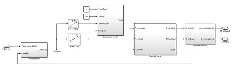
The different components of fuel cell include
a. Compressor model
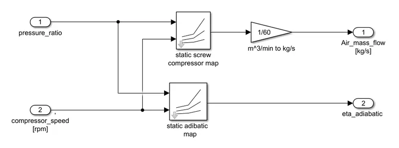
Air Compressors are used to push air into the fuel cell stack. The fuel cell extracts oxygen from the incoming air to enable the reaction at the cathode. In fuel cell systems, the air compressor is also sometimes called an air blower.
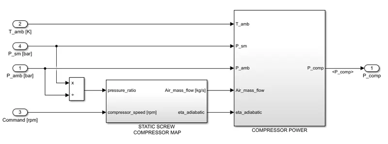
a.i. Static screw compressor map
a.ii. Compressor power
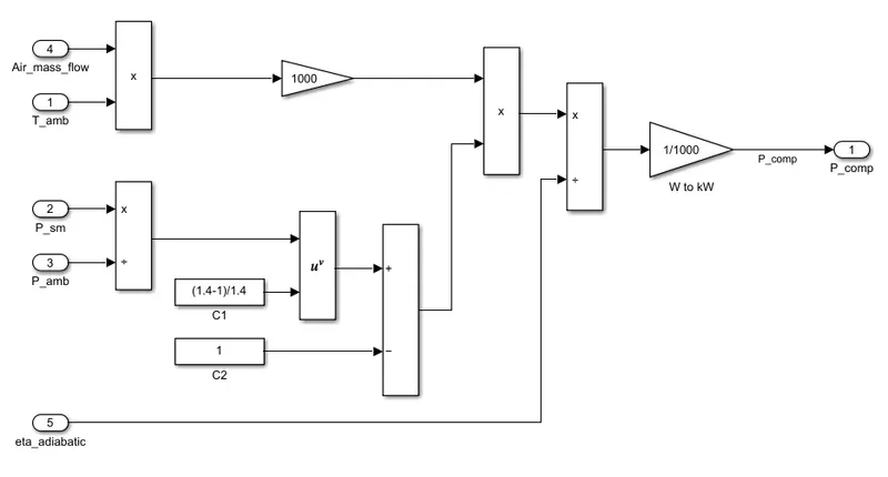
Helps in calculating the power required by the compressor to work
b. Fuel cell stack
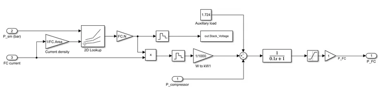
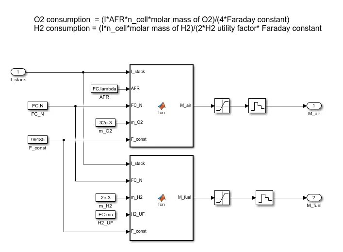
The fuel cell stack gives the working of the fuel cell. The output current, voltage, input fuel and air consumption.
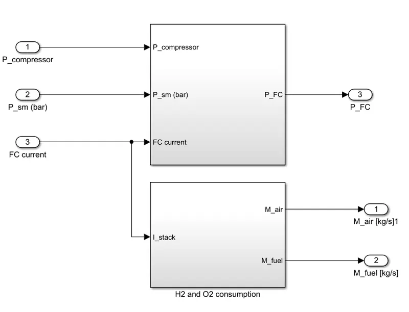
H2 and O2 consumption
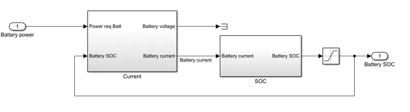
b. Battery model
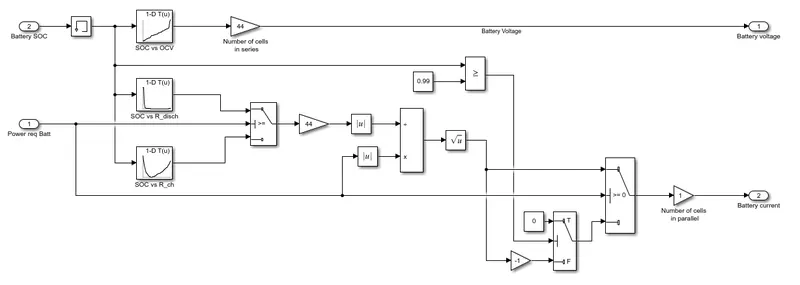
Current calculation
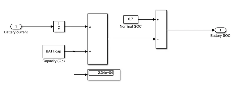
SOC calculation
SOC is estimated by using coulomb counting method.
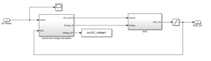
c. UC modelling
III. EMS (Energy Management System)
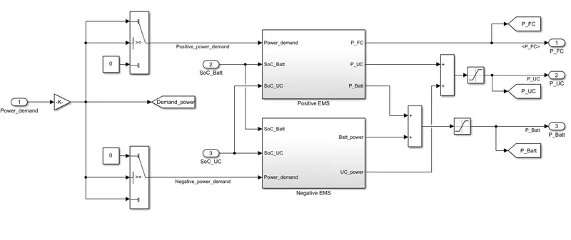
The EMS controls the enrgy flow of the different energy supplying system based on the requirement.
The EMS is required to handlw the different conditions of the vehicle as the properties of each ESS is different
Energy density: FC > Batt > UC
Power density: UC > Batt > FC
So the EMS should take power from each ESS based on the requirement. example for higher power demnad power from UC is taken.
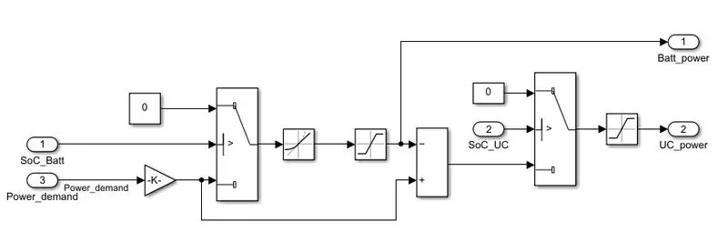
The EMS during regenrative braking should be able to provide power back to battery and UC based on the conditions. As the FC only supplies power.
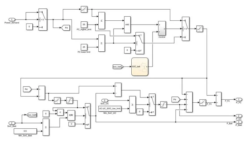
The following algorithm is used to design the EMS
The simulink model is as shown below
Positive power EMS
Negative power EMS
IV. Simulation and Result
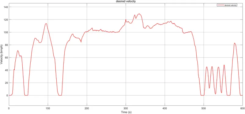
The following drive cycle is used to analyse the working of the Fuel cell EV
Results
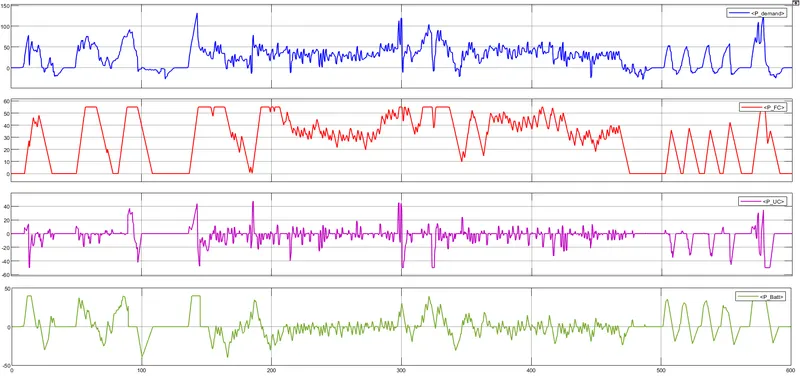
a. Power demand and power supplied by each ESS
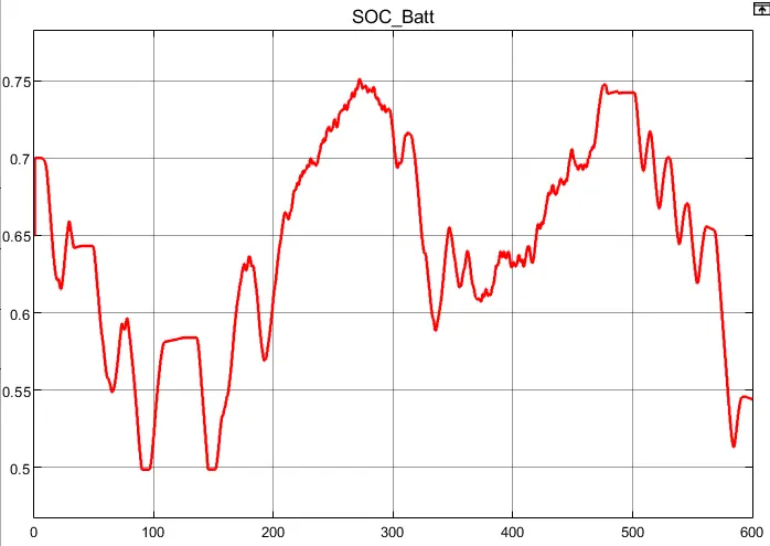
b. SOC of battery
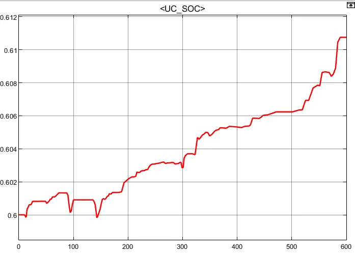
c. SOC of UC
d. H2 and O2 fuel consumption
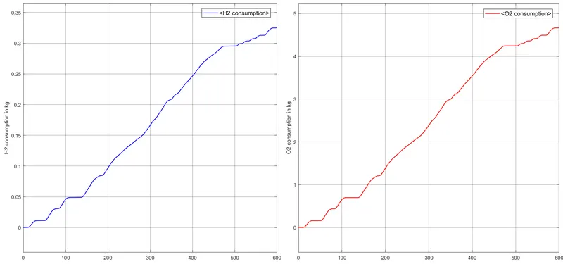
Final consumption
H2: 0.235 kg
O2: 4.663 kg
e. Desired velocity vs actual velocity
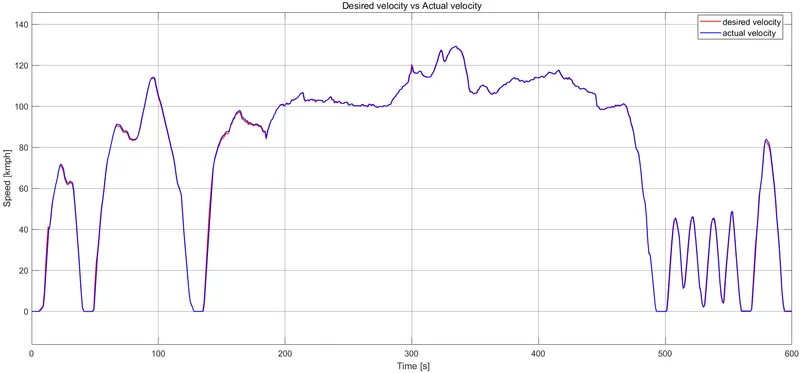
Observation:
- The desired velocity and the actual velocity are same, it shows the good dynamic performance of the vehicle and engine.
- The EMS has worked finely based on different conditions
- During high power demand the UC start to supply the power demand.
- During moderate power demand Battery and FC were neccessary to support the power demand.
- The FC turns on when the power demand > 25kW and FC maximum power output was hold at 55kW. Thus FC is able to work at maximum efficiency.
- The FC consumed 0.325kg of fuel, which is less compred to the FC alone vehicle.
- During regenerative braking, the EMS was able to distribute the power among battery and UC, thus helps in conserving the braking energy into electrical and chemical energy.
- The SOC of battery and UC is monitored and helps in managing the healthy operation of the ESSs.
- The engine was able to supply the required power for the vehicle.
V. CONCLUSION
The Fuel cell electric vehicle has designed and modelled in simulink environment. The model has worked as per desired with same actual and desired velocity. The EMS working has analysed and was able to support all type of power demands and regenrtive braking by keeping all ESSs in its rated operating range. The fuel cell along with battery and UC have a great performance comparing to individula performance as each of them have its own properties. The fuel and air consumption of the Fuel cell has anlaysed and is minimum compared to fuel cell alone vehicle and also having higher dynamic performance.