Project-1: Powertrain for aircraft in runways
1. Total weight of various types of aircrafts
There are different kinds of aircrafts based on its mode of use like cargo, passenger, military, supersonic, etc. Also there are different types of aircrafts in each category based on size and weight of the aircrafts. The weight of the aircraft can be broadly classified into three parts
- Operating Empty Weight: It is the basic weight of an aircraft including the crew, all fluids necessary for operation such as engine oil, engine coolant, water, unusable fuel and all operator items and equipment required for flight but excluding usable fuel and the payload.
- Total Payload: It is the carrying capacity of an aircraft. It includes cargo, people, extra fuel. In the case of a commercial airliner, it may refer only to revenue-generating cargo or paying passengers.
- Total Fuel Loaded: The weight of the fuel required for the aircraft.
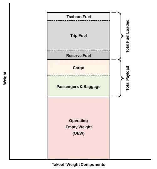
Based on the above braod classification, the maximum weight that aircraft carries are given below
| Aircraft | Empty Weight | Max Fuel Weight | Max Cargo Weight | Max Gross Takeoff Weight |
| Antanov AN-225 | 285,000 kg | 300,000 kg | 190,000 kg | 640,000 kg |
| Airbus A380-800 | 277,000 kg | 254,000 kg | 84,000 kg | 575,000 kg |
| Boeing 747-800 | 220,100 kg | 194,000 kg | 134,000 kg | 447,700 kg |
| Airbus A340-500 | 168,000 kg | 175,000 kg | 54,000 kg | 372,000 kg |
| Boeing 777-300ER | 168,000 kg | 145,500 kg | 67,100 kg | 352,000 kg |
| Boeing 787-10 | 135,500 kg | 101,500 kg | 57,300 kg | 254,000 kg |
| Boeing 737-900 | 44,700 kg | 24,000 kg | 20,200 kg | 85,000 kg |
| Airbus A320-100 | 42,600 kg | 22,100 kg | 20,000 kg | 68,000 kg |
| Embraer 190 | 28,800 kg | 13,000 kg | 13,100 kg | 48,000 kg |
| Gulfstream G650 | 24,500 kg | 21,900 kg | 3,000 kg | 45,200 kg |
| Bombardier CRJ900 | 21,850 kg | 8,900 kg | 2,760 kg | 36,500 kg |
| Bombardier Q400 | 17,800 kg | 5,300 kg | 8,500 kg | 28,000 kg |
| Learjet 75 | 6,300 kg | 2,750 kg | 1,300 kg | 9,700 kg |
| Cessna Citation CJ4 | 4,700 kg | 2,650 kg | 1,000 kg | 7,800 kg |
| Beechcraft King Air B100 | 3,200 kg | 1,450 kg | 1,900 kg | 5,400 kg |
| Diamond DA50 RG | 1,450 kg | 155 kg | 560 kg | 2,000 kg |
| Beechcraft Bonanza G36 | 1,150 kg | 200 kg | 385 kg | 1,660 kg |
| Cessna 206H | 990 kg | 235 kg | 520 kg | 1,630 kg |
| Sirrus SR22 | 1,000 kg | 220 kg | 430 kg | 1,630 kg |
| Cessna 172R | 770 kg | 170 kg | 255 kg | 1,100 kg |
2. Difference between ground speed and air speed
Ground Speed: Ground speed is the speed of the aircraft relative to the ground.
Air Speed: Air speed is the speed of the aircraft relative to the air it is flying in.
Wind Speed: It is the speed of the air flowing with respect to ground.
All the speeds are calculated in vector quantity and varies with respect to direction.
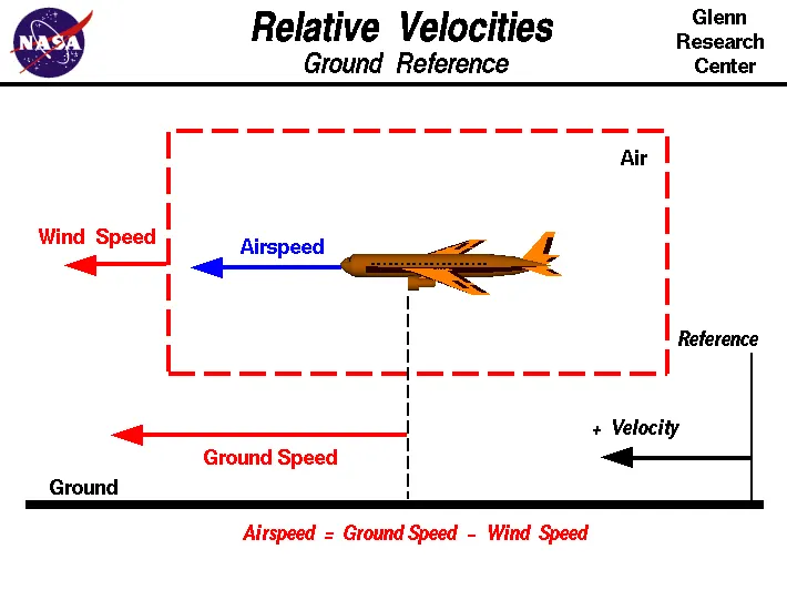
In Comparison
- Airspeed is what determines whether there is enough airflow around an aircraft to make it fly, ground speed is what determines how fast an aircraft will get to its destination.
- The relationship between airspeed and ground speed is fairly simple. Ground speed is simply the sum of airspeed and wind speed.
- If the aircraft is flying in the same direction as the wind is blowing, the aircraft experiences tailwind, and its ground speed is higher than its airspeed.
- If the wind is blowing against the direction the aircraft is traveling in, the aircraft experiences headwind, and its ground speed is lower than its airspeed.
3. Why is it not recommended to use aircraft engine power to move it on the ground at Airport
When the aircraft moves inside airport with its own power is called taxiing. The aircrafts uses taxiing under taxiways whic are away from the terminals. Near to the terminals or while reversing the aircrafts doesn't utilise its power to manuever, it is done by a tow-truck. The tow-truck helps in moving the aircraft to the taxiway and later the aircraft utilise its power to manuever to the take-off point.
The tow-truck either connects to the front axle (for light weight aircrafts) or lifts up the front axle (for medium and hevay weight aircrafts) and tows it to the taxiway. The front-axle is lifted for heavy aircraft because towing it will cause the tire to slip, but lifting will give extra vertical load on the tow truck and the friction between tire and ground will be increased, so tire slip is reduced.
The disavdvantages of taxiing near terminals are
- The aircraft uses its jets or propler to move, this will cause air blast and will damage the buildings, equipments, etc, and also dangerous for the ground crews and vechicles.
- While reversing it uses reverse thrust this will blow up the sands and other junks in the terminal point and will eneter into the engine and can cause damage to the engine.
- The thrust created by the engine is high and can suck anything infront of it and thus it is damage to both humans and aircraft.
- The pilot in the cabin will have only limited view angle of surroundings and may can damage the aircraft while manuevering.
The advantage of using tow-truck for moving the aircraft around the terminals are
- Better viewing angle.
- No hamrful to the surroundings because aircraft engine is at standstill.
- More fuel efficient as aircraft uses more fuel to run the engine than that of tow-truck.
- The sound pollution will be reduced as aircraft engine creates high sound and noises.
- Safety of the ground crews, vehicles and terminals can be ensured.
4. How an aircraft is pushed to runway when its ready to take off?
The aircraft starts from the terminal to take-off and it caries following procedures
- Pushback: Pushback is an airport procedure during which an aircraft is pushed backwards away from its parking position, usually at an airport gate by external power. Pushbacks are carried out by special, low-profile vehicles called pushback tractors or tugs.
-
Pushbacks at busy aerodromes are usually subject to ground control clearance to facilitate ground movement on taxiways. Once clearance is obtained, the pilot will communicate with the tractor driver (or a ground handler walking alongside the aircraft in some cases) to start the pushback. To communicate, a headset may be connected near the nose gear.
-
Since the pilots cannot see what is behind the aircraft, steering is done by the pushback tractor driver and not by the pilots. Depending on the aircraft type and airline procedure, a bypass pin may be temporarily installed into the nose gear to disconnect it from the aircraft's normal steering mechanism.
-
Once the pushback is completed, the towbar is disconnected, and any bypass pin removed. The ground handler will show the bypass pin to the pilots to make it clear that it has been removed. The pushback is then complete, and the aircraft can taxi forward under its own power.

-
- Taxiing: Taxiing is the movement of an aircraft on the ground, under its own power. The taxiing is done when the aircraft reaches the taxiway and moves until it recahes to the take-off point. At this time engine is not completly engaged and the brakes are also engaged during this.
- Before reaching takeoff point the aircrafts are aligned perfectly straight to runway and the functioning of all the equipments is tested over there like flaps, brakes, pressure, engine, etc.
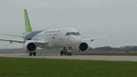
- Take off: Takeoff is the phase of flight in which an aerospace vehicle leaves the ground and becomes airborne. The aircraft completly uses its full engine power and runs through the runway and then lifts up to become airborne.
5. Learn about Take off Power, Tyre design, Rolling resistance, Tire pressure and Braking forces while landing
a. Take-off Power
Take-off power is the power required by the aircraft to successfully take-off from the runway considering the overall weight of the aircraft, length of runway, environmental conditions.
The aircraft while take-off it requires enogh speed, thrust and lift to fly. The following forces acts on the aircraft while take-off
- Rolling reistance force, `F_(rr)`
- Air drag, `F_(air)`
- Acceleration force, `F_(a)`
- Lifting force (similar to hill climb), `F_(L)`
During take off run, the Thrust force `F_(T)`given by the aircraft engine drives the airplane forward, The force equation can be expressed as
`F_(T) = F_(rr)+F_(a)+F_(air)`
So the acceleration of the aircraft is given by
`F_(a) = F_(T)-F_(rr)-F_(air)`
`mfrac(dv)(dt) = F_(T)-F_(rr)-F_(air)`
`a = frac(dv)(dt) = frac(F_(T)-F_(rr)-F_(air))(m)`
where m is the mass of the aircraft,
The acceleration is required until the speed of the aircraft reaches it required speed.
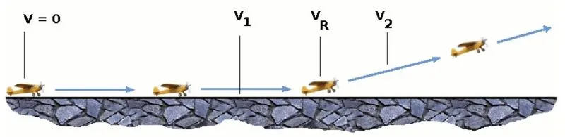
The following animation will help in understanding the different speed
- `V1` - Decision speed
- `V_R` - Rotation speed
- `V2` - Safe climb speed
- `V_(stall)` - Stalling speed

Different speeds at different region
The following conditions are needed to determine the takeoff
- As the airplane accelerates from zero velocity, at some point it will reach the stalling velocity `V_(stall)`, is the lowest speed that the aircraft can be flown before the airflow starts to separate from wings as the angle of attack becomes too great.
- The airplane continues to accelerate until it reaches the decision speed, V1. This is the speed at which the pilot can successfully continue takeoff even though an engine failure (in a multiengine aircraft) would occur at this point. If an engine fails before V1 is achieved, the takeoff must be stopped. If an engine fail after V1 is reached, the takeoff has to be completed.
- The airplane continues to accelerate until the takeoff rotational speed, VR is achieved. At this velocity, the pilot initiates by elevator deflection a rotation of the airplane in order to increase the angle of attack and to overcome the weight. Attention should be paid not to stall.
- After reaching VR, the aeroplane must be accelerated to V2. During the acceleration to speed V2, the nose gear may be raised off the ground at a speed not less than VR. However, landing gear retraction may not be begun until the aeroplane is airborne. The aeroplane must reach V2 before it is 35 ft above the take-off surface .
Thus for reaching the required velocity the aircraft requires take-off power with respect to the runway length and environmental condition. The required acceleration is calculated and the the take-off power. For light aircraft, usually full power is used during takeoff. Large transport category (airliner) aircraft may use a reduced power for takeoff, where less than full power is applied in order to prolong engine life, reduce maintenance costs and reduce noise emissions.
b. Tyre Design
Tyres are one of the most important components of aircraft. They help to absorb the shock of landing and provide cushioning. It also provides the necessary traction for braking and stopping of an aircraft.
An aircraft tire or tyre is designed to withstand extremely heavy loads for short durations. The number of tires required for aircraft increases with the weight of the aircraft, as the weight of the airplane needs to be distributed more evenly. Aircraft tire tread patterns are designed to facilitate stability in high crosswind conditions, to channel water away to prevent hydroplaning, and for braking effect.
Aircraft tires also include fusible plugs (which are assembled on the inside of the wheels), designed to melt at a certain temperature. Tires often overheat if maximum braking is applied during an aborted takeoff or an emergency landing. The fuses provide a safer failure mode that prevents tire explosions by deflating in a controlled manner, thus minimizing damage to aircraft and objects in the surrounding environment.
Carcass plies are used to form the tire. They are sometimes called casing plies. An aircraft tyre is constructed for the purpose it serves.
- They support the weight of an aircraft while it is on the ground.
- It also provides the necessary traction for braking and stopping of an aeroplane.
- Tyre also helps to absorb the shock of landing and provide cushioning the roughness of takeoff, roll-out, and taxi operations.
The cutaway section of bias-ply tyre (commonly used), it consist of different parts they are
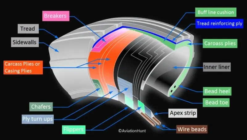
- Tread: The tread is made of rubber mixed with other additives to obtain the desired level of toughness, durability, and resistance to wear. The tread pattern is designed to aircraft operational requirements, with the ribbed tread design used widely due to its good traction under varying runway conditions.
- Sidewall: The sidewall is a protective layer of rubber that covers the outer casing ply. It extends from the tread edge to the bead area.
- Tread Reinforcing Ply: One or more layers of fabric that strengthens and stabilizes the tread area for high-speed operation. It also serves as a reference for the buffing process when tires are retreaded.
- Buff Line Cushion: The buff line cushion is made of rubber compound to enhance the adhesion between the tread reinforcing ply and the breakers or casing plies. It is of sufficient thickness to allow for the removal of the old tread when the tire is retreaded.
- Breakers: Breakers are reinforcing plies of rubber-coated fabric placed under the buff line cushion to protect casing plies and strengthen and stabilize the tread area. They are considered an integral part of the casing construction.
- Casing Plies: Alternate layers of rubber-coated fabric (running at opposite angles to one another) provide the strength of the tire.
- Wire Beads: Hoops of high tensile strength steel wire that anchor the casing plies and provide a firm mounting surface on the wheel. The outer edge of the bead that fits against the wheel flange is called the bead heel. The inner bead edge is called the bead toe.
- Apex Strip: A wedge of rubber affixed to the top of the bead bundle.
- Flippers: Layers of rubberized fabric that help anchor the bead wires to the casing and improve the durability of the tire.
- Ply Turnups: The casing plies are anchored by wrapping them around the wire beads, thus forming the ply turnups.
- Chafer: A protective layer of rubber and/or fabric located between the casing plies and wheel to minimize chafing.
- Liner: In tubeless tires, the liner is a layer of low permeability rubber that acts as a built-in tube and restricts gas from diffusing into the casing plies. In tube-type tires, a thinner liner is used to prevent tube chafing against the inside ply.
The technical aspects of the tyre includes
- Retreading – Retreading is methods of restoring a worn tyre by renewing the tread area or by renewing the tread area plus one or both sidewalls. Repairs are included in the tyre retreading process.
- Load Rating – Load rating is the maximum permissible load at a specified inflation pressure.
-
Ply Rating – Ply Rating is used to identify the maximum recommended load rating and inflation pressure for a specified tyre. It is an index of tyre strength.
-
Speed Rating – The speed rating is the maximum takeoff speed to which the tyre has been tested.
-
Skid Depth – Skid depth is the distance between the tread surface and the deepest groove as measured in the mould.
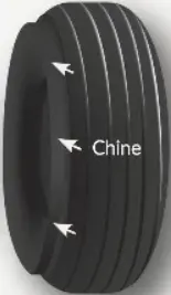
The aircraft tyres sometimes uses "Chines" with the tyre, they are also called deflectors. Chine tyre used on the nose wheel of aircraft, specially fuselage-mounted jet engines. It diverts runway water away from the engine inlets.
c. Rolling resistance and Tyre pressure
Rolling resistance
Tire rolling resistance is the energy that your vehicle needs to send to your tires to maintain movement at a consistent speed over a surface. In other words, it is the effort required to keep a tire rolling. The main contributor to rolling resistance is the process known as hysteresis. Hysteresis is essentially the energy loss that occurs as a tire rolls through its footprint. The energy loss must be overcome by the vehicle’s engine, which results in wasted fuel.
Decreasing the rolling friction increase the fuel efficiency of the vehciel but the braking efficiency decreases. So it is recommende to have a balanced rolling friction for the tire.
The coefficient of rolling resistance of the aircraft tires at different surfaces.
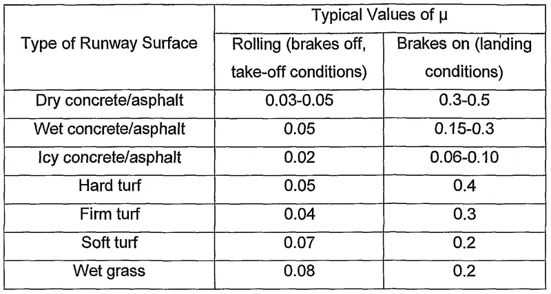
The rolling resistance force is given by
`F_(rr) = mu.m.g`
Tire pressure
The tire pressure varies with respect to each aircraft, for Boeing 777-300ER main tires is inflated to 220 psi. The pressure is required to kept at rated level over pressure and under pressure effects the performance of the tire.
- Over pressure of tire causes
- deformation of tire
- slipping of tire
- high shocks
- bad grip with the runway
- Under pressure of tire causes
- stablity loss
- effects the speed of the vehicle
- high rolling resistance causes higher temperature of tire
- fast wear and tear
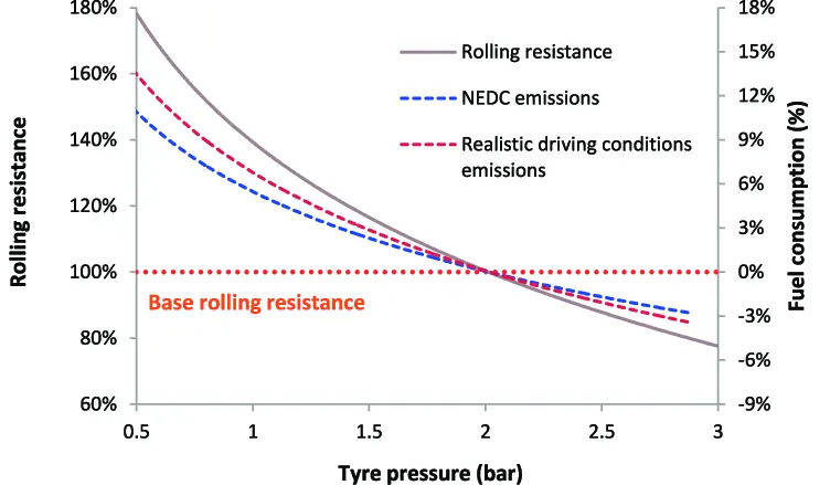
So that tire pressure is maintained at the required level. The pressure inversely effets the rolling resistance.
d. Braking forces while landing
There are different mechanism of braking in aircrafts based on different types of aircraft, they are
- Disc brake - frictional braking
- Thrust reversers (in jet engine)
- Spoilers and air brake
Disc brake:
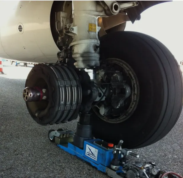
Aircraft typically use disc and multi-disc brakes .It mainly consists of rotating disc attached to the wheel assembly, brake callipers which are held stationary and contains the brake pads made of material such as asbestos, ceramics, carbon etc. When brake pedal is pressed, brake fluid under pressure flows from master cylinder to the slave cylinder via tubes. The slave cylinder consists of piston which gets actuated by the force of incoming fluid pressure. The piston forces the brake pads against the rotating disc. The friction between the brake pad and disc surface, resist its rotating motion and stops it. Disc brakes used these days are differential type i.e. the left and right unit are independent of one another. This also provides increased manoeuvrability.
Multiple disc brakes consist of series of discs, the steel stators which is a stationary unit is keyed to the bearing carrier and the rotors form the rotating part and are keyed to the wheel. Automatic adjuster is used for providing clearance between the rotor and stator layers. Under the action of hydraulic pressure, these series of disc get compressed, forcing the wheel to slow down due to friction. These days the discs are provided with slots for better heat dissipation at high temperature. Also, Carbon fibre is being extensively used as rotor material for the brakes because of its low weight and the ability to withstand high heat and temperature. Although it requires lesser maintenance than the conventional brakes but the cost of manufacturing is comparatively high.
A brake assembly on a Boeing 737NG main landing gear
Spoilers and Air Brakes:
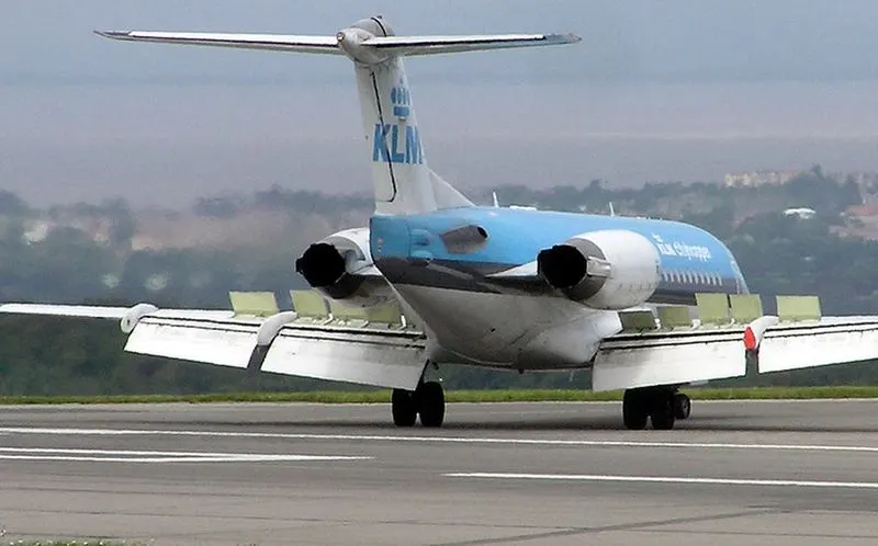
Spoilers are devices used to destroy the lift of an aircraft. These are flap like structure of rectangular cross-section whose leading edge is hinged to the wings (at an angle) disturbing the streamlined f low of air thereby changing the amount of lift. The net force on aeroplane in the vertical direction is equal to weight minus lift. Thus, when the spoilers are employed lift gets reduced as a result the net downward force acting on the body increases.
Flight spoilers are used to reduce lift, without increasing speed to a very high rate. This allows easier descent of the aircraft .Ground spoilers also known as lift dumpers are deployed on landing. They slow down the vehicle by increasing the drag and also decrease the lift dramatically. As a result, weight of the aircraft is transferred from the wings to the undercarriage. This leads to ease of braking and also reduces chances of skidding.
Air brakes also known as dive brake is a device which consists of a series of metal blades which when activated increase the drag on the aircraft. They are utilised in high performance aircrafts and are located above or below the wing or near the fuselage. Air brakes differ from spoilers that they have minimal effect on the lift. Rather they increase the drag by biting into the air. Another difference is that Air brakes are either fully stowed or fully deployed, while spoilers can be deployed at different positions.
Thrust Reversers:
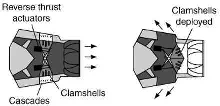
In addition to the normal brakes, thrust reversers are employed for decelerating the aircraft after touchdown especially when the runways are snow covered or icy. Thrust reversers work on the principle of reversal of the direction of the exhaust gases or changing the propeller pitch in order to create a drag force to oppose the motion of aeroplane. Thrust reversal is mainly used to reduce the stopping distance. It enables landing on smaller runways, reduction in the wheel brake wear and taxi distance. It is also used in case of Rejected take offs.
There are several methods for thrust reversals in turbojet or turbofan engine
- Clam shell type
- Bucket Target type
- Cascade type
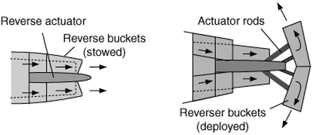
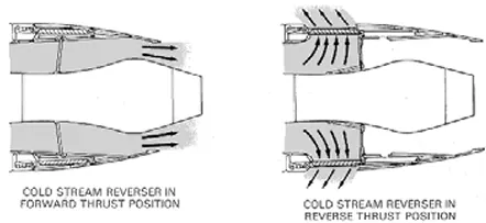
The aircrafts are slowed down by using any or combination of these braking system. Mostly the aircrafts uses airbrakes and disc brakes for slowing down, for large and medium jet aircrafts the reverse thrusters are also used in combination with the disc and air brakes.
6. Calculating the Force and Power required by the tow-truck to move the aircraft.
A towing hook attaches its one end to the aircraft and the other end to the pushback tractor. The driver receives a go ahead signal from Pilot and begins the pushback operation.
It pushes the aircraft back and also steers it so that the aircraft ends up in correct position on the taxiway (a connecting pathway between aircraft stand and runway).
Pilot then gives an okay to disengage signal to the pushback tractor driver at which he unhooks the towing bar and steers the pushback tractor away from the aircraft.
However their are many restriction regarding the towing speed and acceleration.
- The maximum speed of tow-truck while pushback is 5kmph
- The maximum speed of tow-truck while pushpull is 10kmph.
- The acceleration must be slower as possible.
On regarding these limitations the speed of the tow-truck is assumed to be 10kmph and acceleration from 0 to 10 kmph takes 15s.
The following are the assumptions taken for calculating the overall tractive power required by the vehicle. As the tow truck tows the aircraft, the power calculation is splitted into two parts fro two truck and aircraft seperrately and at last adding the power required by both for calculating the total tractive power required by the tow truck to pushpull the aircraft.
The assumtions are
| TO FIND THE POWER OF THE VEHICLE | ||
| VEHICLE DETAILS | ||
| Vehicle | Aircraft Boeing 737 | Tow Vehicle TLD TMX-50 |
| Kerb wieght in kg | 41000 | 4500 |
| Payload weight in kg | 30000 | 500 |
| Total wieght in kg | 71000 | 5000 |
| Vehicle frontal height in m | 3.76 | 1.72 |
| Vehicle frontal width in m | 4.01 | 2.60 |
| Total frontal area of vehicle m2 | 15.08 | 4.47 |
| VEHICLE RUNNING DETAILS | ||
| Speed of Vehicle in kmph | 10.000 | 10.000 |
| Speed of Vehicle in mps | 2.778 | 2.778 |
| Top speed from 0 to Vf (kmph) | 10.000 | 10.000 |
| Time required for top speed (s) | 10.000 | 10.000 |
| Acceleration of vehicle mps2 | 0.278 | 0.278 |
| TERRAIN DETAILS | ||
| Road inclination in degree | 0.000 | 0.000 |
| Drag coefficient, Cd | 0.026 | 0.900 |
| Air density | 1.225 | 1.225 |
| Coefiicient of Rolling friction | 0.020 | 0.030 |
The road inlination is taken 0 deg, as the airport runways and terminals are mostly at 0 deg inclination or on flat surface.
The following excel calculator is used to determine the total forces and power required by the varioius resistive forces acting on the both vehicles.
| TO FIND THE POWER OF THE VEHICLE | ||
| VEHICLE DETAILS | ||
| Vehicle | Aircraft Boeing 737 | Tow Vehicle TLD TMX-50 |
| Kerb wieght in kg | 41000 | 4500 |
| Payload weight in kg | 30000 | 500 |
| Total wieght in kg | 71000 | 5000 |
| Vehicle frontal height in m | 3.76 | 1.72 |
| Vehicle frontal width in m | 4.01 | 2.60 |
| Total frontal area of vehicle m2 | 15.08 | 4.47 |
| VEHICLE RUNNING DETAILS | ||
| Speed of Vehicle in kmph | 10.000 | 10.000 |
| Speed of Vehicle in mps | 2.778 | 2.778 |
| Top speed from 0 to Vf (kmph) | 10.000 | 10.000 |
| Time required for top speed (s) | 10.000 | 10.000 |
| Acceleration of vehicle mps2 | 0.278 | 0.278 |
| TERRAIN DETAILS | ||
| Road inclination in degree | 0.000 | 0.000 |
| Drag coefficient, Cd | 0.026 | 0.900 |
| Air density | 1.225 | 1.225 |
| Coefiicient of Rolling friction | 0.020 | 0.030 |
| FORCES | ||
| ROLLING RESISTANCE FORCE (N) | 13930.200 | 1471.500 |
| AIR DRAG FORCE (N) | 1.853 | 19.022 |
| HILL CLIMB FORCE (N) | 0.000 | 0.000 |
| ACCELERATION FORCE (N) | 19722.222 | 1388.889 |
| TOTAL FORCE (N) | 33654.275 | 2879.410 |
| POWERS | ||
| ROLLING RESISTANCE POWER | 38.695 | 4.088 |
| AIR DRAG POWER | 0.005 | 0.053 |
| HILL CLIMB POWER | 0.000 | 0.000 |
| ACCELERATION POWER | 27.392 | 1.929 |
| TOTAL POWER | 66.092 | 6.069 |
| POWER CALCULATION | ||
| Top speed from 0 to Vf (mps) | 2.778 | 2.778 |
| ROLLING RESISTANCE POWER | ||
| Coefficient of Rolling friction | 0.020 | 0.030 |
| Total mass of Vehicle in kg | 71000.000 | 5000.000 |
| Acceleration due to gravity, g (m/s2) | 9.810 | 9.810 |
| Rolling resistance force (N) | 13930.200 | 1471.500 |
| Speed of vehicle (m/s) | 2.778 | 2.778 |
| Rolling resistance power (kW) | 38.695 | 4.088 |
| AIR DRAG POWER | ||
| Drag Coefficient, Cd | 0.026 | 0.900 |
| Air density | 1.225 | 1.225 |
| Vehicle frontal are (m2) | 15.078 | 4.472 |
| Speed of vehicle (m/s) | 2.778 | 2.778 |
| Air drag force (N) | 1.853 | 19.022 |
| Air drag power (kW) | 0.005 | 0.053 |
| HILL CLIMB POWER | ||
| Total mass of Vehicle in kg | 71000.000 | 5000.000 |
| Road inclination in degree | 0.000 | 0.000 |
| Acceleration due to gravity, g (m/s2) | 9.810 | 9.810 |
| Hill climb Force (N) | 0.000 | 0.000 |
| Hill climb Power (kW) | 0.000 | 0.000 |
| ACCELERATION POWER | ||
| Total mass of Vehicle in kg | 71000.000 | 5000.000 |
| Top speed from 0 to Vf (mps) | 2.778 | 2.778 |
| Time required for top speed (s) | 10.000 | 10.000 |
| Acceleration of vehicle mps2 | 0.278 | 0.278 |
| Acceleration force (N) | 19722.222 | 1388.889 |
| Acceleration Power (kW) | 27.392 | 1.929 |
| TOTAL POWER | 66.092 | 6.069 |
The power and forces are calculted based on the following equations
A. Rolling resistance Power
It is the force or power which acts on a vehicle due to adhesive force between tire and road. So this force mainly depends on mass and velocity of vehicle, tire parameters and road condition. Rolling resistive force is given by
Frr = `mu_(rr)`* m * g
Prr = Frr * V
where,
`mu_(rr)` - rolling resistance coefficient
m - mass of vehicle, kg
g - acceleration due to gravity, m/s2
V - velocity of vehicle, m/s
B. Hill climb Power
This force is due to the gravitational force acting on the vehicle and is proportional to the grade of the road.
Fhc = m * g * `Sin(phi)`
Phc = Fhc * V
where,
`phi` - grade of the road in radians
C. Air Drag Power
This force acting on the vehicle is due to the resistive force due to the air which includes both shape and skin effect of the vehicle.
Fad = 0.5*`rho`* A * Cd * V * V
Pad = Fad * V
where,
`rho` - air density, kg/m3
A - frontal area, m2
Cd - Air drag coefficient
D. Acceleration Power
This force is due to the moment of inertia of the vehicle, include both translational and rotational components of the vehicle.
Facc = m*a
Pacc = 0.5* m * Vf * Vf/ta
where,
a - acceleration of the vehicle, m/s2
ta - acceleration time, s
Vf - final velocity, m/s
TOTAL POWER
Total power acting on a vehicle is sum of all the powers above
Pte = Prr + Pad + Phc + Pacc in kW
6.b. Simulink model for calculation of Force and Power of Airplane and Tow-truck
The model is build based on the above equations and datas
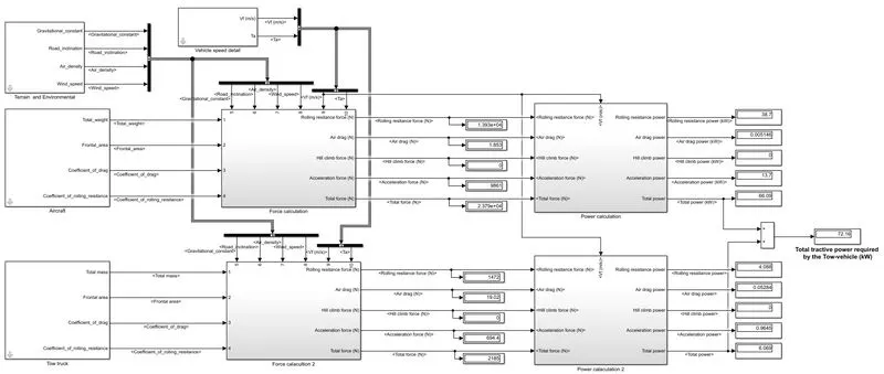
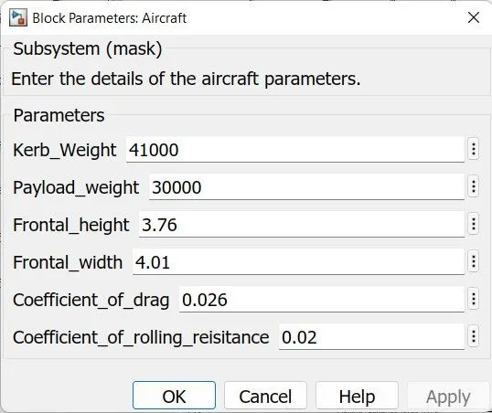
The inputs are referred under masked subsytem
The Airplane input parameters given are:
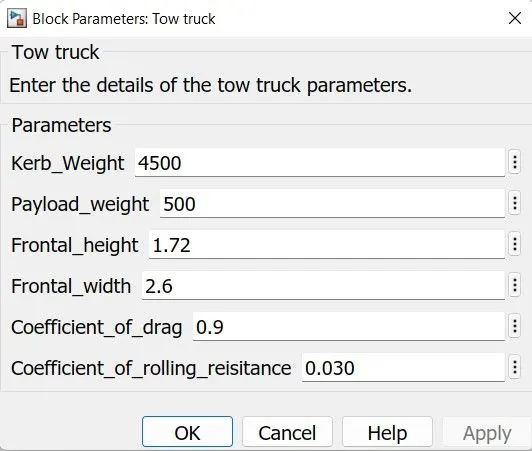
The tow-truck input parameters given are:
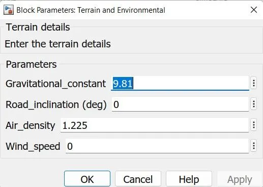
The terrain inputs given are
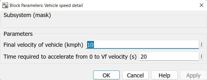
The speed and acceleration time is given as
The following model helps in calculating the force
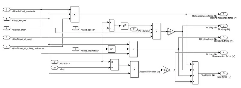
The power is calculated from the force by multiplying the speed of vehicle
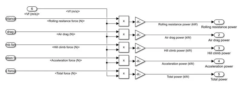
The following results are matched with the excel calculated data.
Model and excel calculator with assumed datas are attached with this.
MATLAB Simulink file: tow_vehicle_power_force_calc.slx
Excel file: power_force_calculation.xslx
7.a. Powertrain block diagram of Tow-truck
The powertrain block diagram of the tow-truck is given as
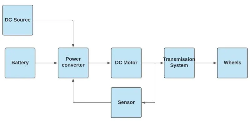
Consist of a
- battery and a DC source for providing the power to the tow-truck.
- power converter for converting the voltage and current levels
- DC motor converts the electrical power into mechanical power
- Transmission system and wheels provides the mechanical power transfer to move the truck.
From the above calculation an engine of 70kW is required by tow-truck to manuever the aircraft.
So the torque required by the rear axle is calculated as
`T = F.r.Sin(theta)`
Here `theta` = 90
r is the radius of the wheel, which is r = 0.38m
The force required is F = 36.5kN
So the required torque is
T = 36.5*1000*0.38*1
T = 13.87kNm
So the rear axle requires 13.87kNm of torque
The driving torque is provided by the motor, then it is transferred to the gera system and then to differential and then to rear axle. So the efficiency of each part is required to under taken.
The combined efficiency of the system is taken as 85%
The gera ratio is taken as 1:10
So the required torque at end of motor is
`T_m = T_(ra).G/eta_(dt)`
`T_m` = 13.87*(1/10)/0.85
`T_m` = 1.631kNm
The maximum speed of the tow truck is choosen to be 15kmph.
So the maximum RPM is choosen by converting the speed into RPM.
So the tire completes `2*pi*r` (= 2.386m) distance at one rotation, for acheiving 15kmph (= 4.167mps). The tire needs to rotate at 1.75 rotation per second or in RPM it is 1050 RPM.
The max RPM of motor is 105/G = 1050 RPM.
So the motor has to bes designed for
Tm = 1.631kNm
Pm = 82.35 kW
Rated RPM = 1050
The motor voltage is taken as 315V
The battery voltage is taken as 480V.
And Power converter is selected according to it.
The model for above given tow vehicle with DC7 block is
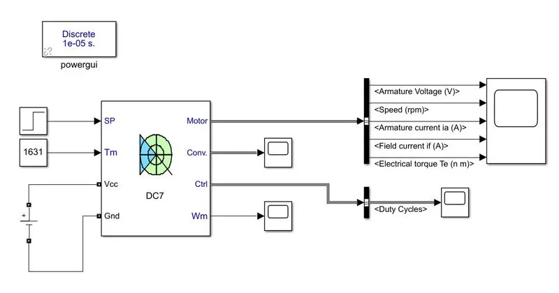
The result for the vehicle moving at 10kmph with aircraft is as shown below, for 10kmph the required motor RPM is 700 RPM, calaculated based on the above data.
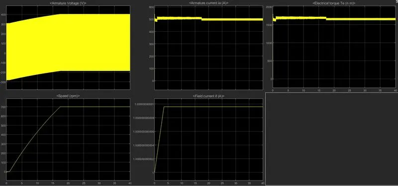
The duty cycle required by the power converter to reach the max speed of 10kmph is as shown below
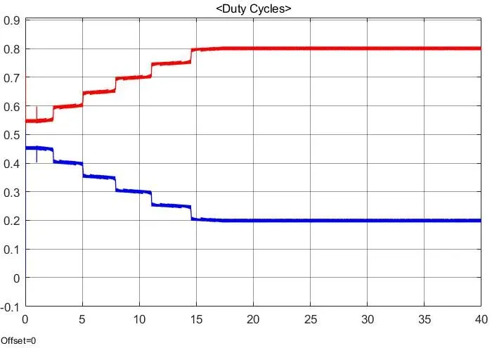
So the maximum duty ratio is given at 80% when vehicle is at 10kmph.
7.b. The model and excel data of assumed vaues are give as attached file
MATLAB model file : powertrain.slx
Excel file: towtruck_assumption.xslx