MESHING AND DO CONNECTIONS ON SUSPENSION ASSEMBLY
OBECTIVE:
- IMPORT THE GIVEN GEOMETRY
- CLEANUP THE GEOMETRY
- GENERATE MIDSURFACE FOR REQUIRED COMPONENTS
- GENERATE VOLUME MESH FOR HOLLOW COMPONENTS
- IMPROVE THE MESH FLOW WITH PROPER FEATURE CAPTURING
- GIVE CONNECTIONS FOR THE SUSPENSION ASSEMBLY
ABSTRACT:
For this project check for the geometrical errors and mesh with the given element Quality criteria. After meshing thickness has to be assigned for mid surfaces.
Use tetra elements to model non-uniform thickness components. Also use Appropriate connections to connect the component
INTRODUCTION:
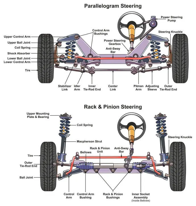
IMPORTANCE OF SUSPENSION IN CAR:
Your car's suspension system is responsible for smoothing out the ride and keeping the car in control. Specifically, the suspension system maximizes the friction between the tires and the road to provide steering stability and good handling. The suspension system also provides comfort for passengers to limiting the impact of particular road conditions to not only the car, but the passengers riding inside.
The suspension system is made up of several components, including the chassis, which holds the cab of the car. The springs support the vehicle weight and absorb and reduce excess energy from road shocks, along with the shock absorbers and struts. Finally, the anti-sway bar shifts the movement of the wheels and stabilizes the car.
Your car's suspension system must be in good condition. Worn suspension components may reduce the stability of the vehicle and reduce driver control, as well as accelerate wear on other suspension system components. Replacing worn or inadequate shocks and struts will help maintain good ride control, as they:
- Control spring and suspension movement
- Provide consistent handling and braking
- Prevent premature tire wear
- Help keep the tires in contact with the road
- Maintain dynamic wheel alignment
- Control vehicle bounce, roll, sway, drive, and acceleration squat
- Reduce wear on other vehicle systems
- Promote even and balanced tire and brake wear
PARTS IN SUSPENSION ASSEMBLY:
Modern suspensions are composed of hundreds of different parts, and vehicles vary tremendously in their suspension designs, but every suspension is composed of certain major subsystems, some of which are more prone to failure than others. The major types of suspension components and systems, and how prone they are to failure, are:
Wheels and tires
Tires aren’t always considered part of the suspension, but they’re arguably the most important component of it. Tires provide traction for acceleration, braking, and cornering, and they absorb small bumps.
Tires wear over time, and are subject to cuts and punctures from hitting sharp objects, and to slow or sudden leaks from impacts. On the other hand, wheels fail (from bending or cracking) much less often, usually only in response to hard impacts from accidents or hitting potholes.
Springs
Every car and truck today has some sort of mechanism to absorb large bumps, and this always includes some form of spring, a metal part that bends in response to force. (A few cars over the years, particular those made by chrysler, have used torsion bars — metal rods that absorb impacts by twisting instead of bending — instead of coil or leaf springs, but these are all different forms of spring.)
Springs can sometimes break when the vehicle hits a bump very hard, and many will sag eventually (after many years), but in general these parts are much less prone to failure than most other suspension components.
Shock absorbers and struts
While springs absorb the bumps, shock absorbers (or, in cars that have them, struts, which are similar to shocks) dampen the motion of the springs after a bump, keeping the vehicle from bouncing excessively.
Shocks and struts are filled with a thick oil, and over time the oil can leak out, causing the shock or strut to fail. Impacts and accidents can also cause leakage or can damage delicate internal parts.
Linkages
Every suspension includes various rods and other connecting pieces that collectively keep the wheels where they’re supposed to be relative to the rest of the vehicle. Most of these linkages are solid metal parts that rarely fail except in major accidents. However, sometimes linkages and associated bushings are sold together, and the failure of a bushing can necessitate replacing the whole assembly.
Bushings, bearings, and joints
Because most parts of any suspension must be movable, the various linkages are connected by flexible connections. These include bushings and bearings, which are connections that allow a small amount of twisting or sliding, often without needing lubrication, and joints, which in automotive applications often use a lubricant such as grease to allow for controlled movement.
Some suspension bushings are made of rubber, which can become brittle or break over time, leading to failure. Many joints tend to wear out, leading initially to looseness and eventually to failure. A couple of the most common culprits are tie rod ends, which are lubricated joints that connects certain steering linkage parts, ball joints, which are found in both the steering system and attached to the control arms, and the bushings that separate the control arms from the vehicle’s frame.
Steering system — all types
Every steering systems contains numerous linkages, some joints such as the tie rod ends mentioned above, and some sort of steering box, the mechanical device that converts rotation of the steering wheel into movement of the car’s wheels.
In general, linkages aren’t very likely to fail, while components such as tie rod ends are. Steering boxes wear out eventually, with rack-and-pinion steering systems in vehicles equipped with hydraulic power steering being the most failure prone.
simaliarly here we do preprocessor of the suspension assembly system using ANSA tool
PROCEDURE:
GIVEN QUALITY CRITERIA
Quality Criteria for Surface Meshing of Tyre and Rim (Element type: Tria) :
|
S.No |
Quality Criteria |
Value |
|
1 |
Target/Average length |
6.5 |
|
2 |
Minimum Length |
5 |
|
3 |
Maximum Length |
10 |
|
4 |
Skewness |
45 |
Quality criteria for Surface Meshing of Non Uniform thickness components other than Tyre and Rim (Element type: Tria) :
|
S.No |
Quality Criteria |
Value |
|
1 |
Target/Average length |
4 |
|
2 |
Minimum Length |
2 |
|
3 |
Maximum Length |
6 |
|
4 |
Skewness |
45 |
Quality Criteria for Volume meshing of all Non Uniform thickness components (Element type: Tetra Elements):
|
S.No |
Quality Criteria |
Value |
|
1 |
Tet-collapse |
0.2 |
Quality criteria for Mid surfacing of Uniform thickness part which has thickness less than 5 mm (Element type: Mixed elements) :
|
S.No |
Quality Criteria |
Value |
|
1 |
Target/Average length |
4 |
|
2 |
Minimum Length |
2 |
|
3 |
Maximum Length |
6 |
|
4 |
Aspect |
3 |
|
5 |
Warpage |
15 |
|
6 |
Skewness |
45 |
|
7 |
Jacobian |
0.7 |
|
8 |
Minimum Quad Angle |
45 |
|
9 |
Maximum Quad Angle |
135 |
|
10 |
Minimum Tria Angle |
30 |
|
11 |
Maximum Tria Angle |
120 |
STEP 1: IMPORT THE GIVEN GEOMETRY
The given geometry was imported to ANSA
COMMAND: FILE- OPEN- CHOOFE FROM LOCATION
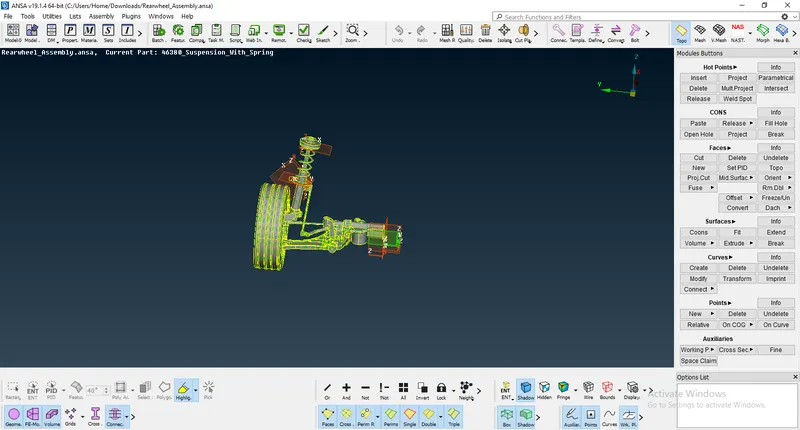
FIG 1. IMPORTED GEOMETRY
The geometry was imported and now we need to look for geometry and cleanup the errors.
STEP 2: CLEANUP THE GEOMETRY
COMMAND: TOOL BAR - CHECKS- GEOMETRY- VISIBLE- EXECUTE
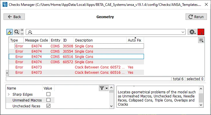
FIG 2. CHECKS MANAGER BEFORE GEOMETRY CLEAUP
The above checks manager shows the errors in the geometry, so we fix the issues either manually or using auto fix option
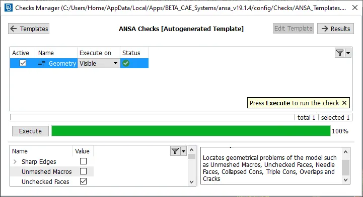
FIG 3. CHECKS MANAGER AFTER CLEANUP
here the check manager status shows ok, so the geometry will be clean
STEP 3: GENERATE MIDSURFACE FOR REQUIRED COMPONENTS
In this geometey there are different types of components, so we can take midsurface for the components which having uniform thickness and the thickness less than 5 mm. rest of the components will do the volume mesh.
LOWER CONTROL ARM:
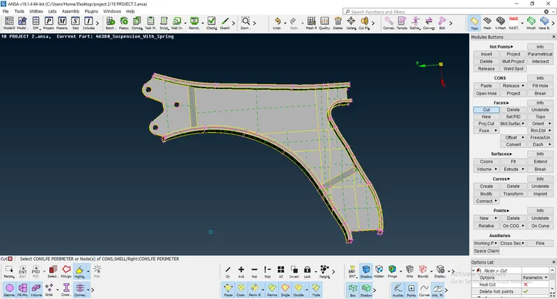
FIG 4. LOWER CONTROL ARM
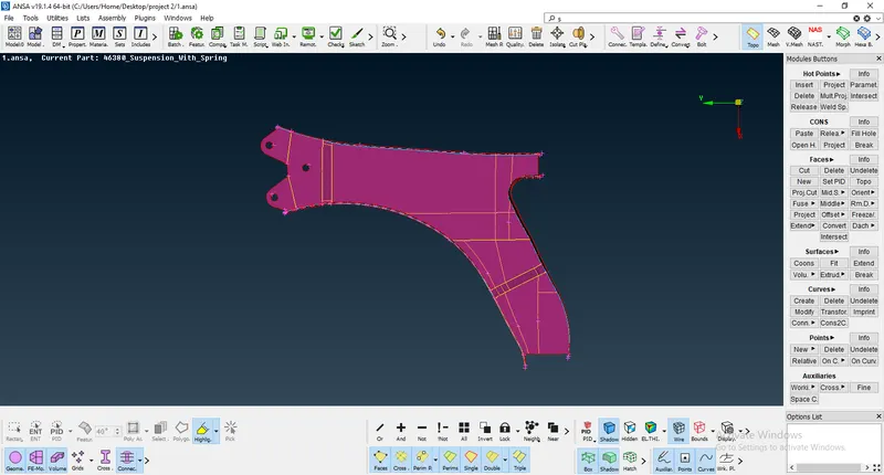
FIG 5. LOWER CONTROL ARM MIDSURFACE
The above LOWER CONTROL ARM has having uniform thickness hence we can take midsurface and do shell mesh for this component.
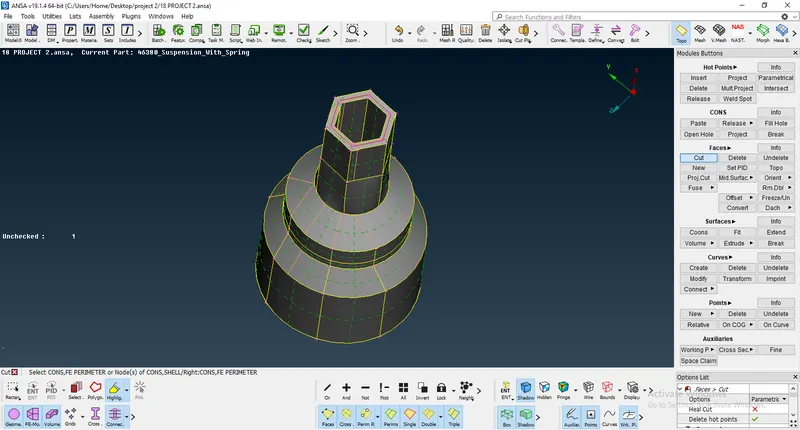
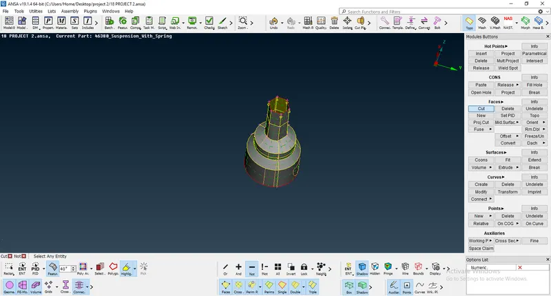
FIG 6. MIDSURFACE
similarly this component also do the same.
STRUT ASSEMBLY PART:
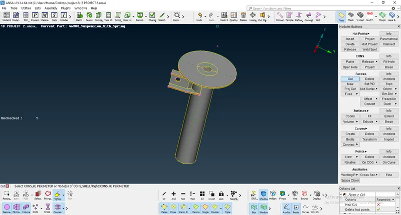
FIG 7. STRUT ASSEMBLY PART
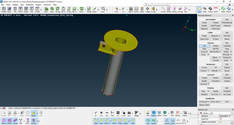
FIG 8. STRUT ASSEMBLY PART MIDSURFACE
similarly the strut assembly part also need to take mid surface
STEP 4: GENERATE VOLUME MESH FOR HOLLOW COMPONENTS
The component which has having the variying thickness and have hollow structure, we will do volume mesh fo those components.
hence in the given quality criteria for TYRE and RIM are choosen
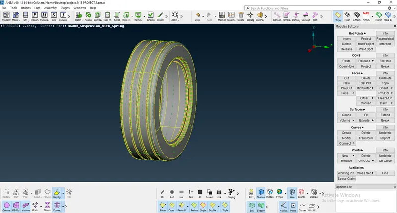
FIG.9 TYRE GEOMETRY
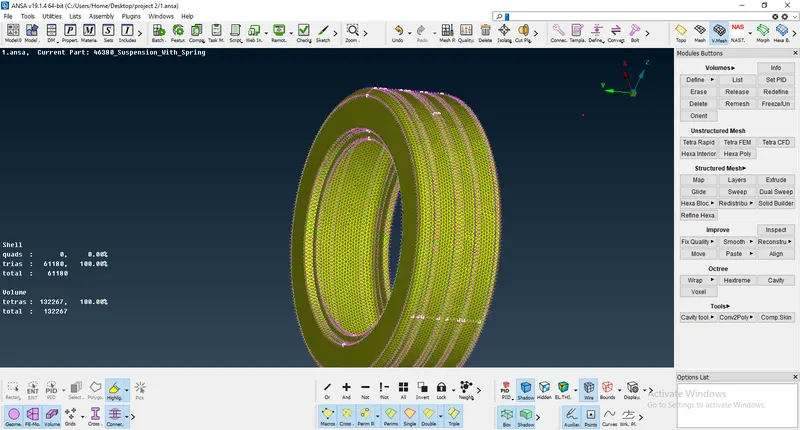
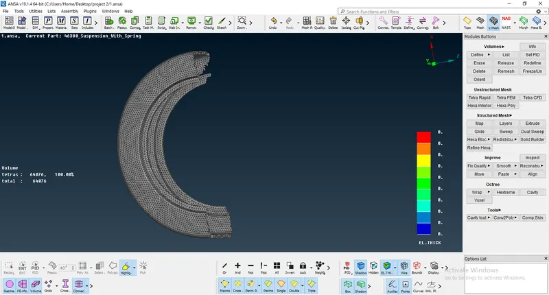
FIG. 10 TYRE VOLUME MESH
Either we can do batch mesh or do a manual mesh, first we do tria mesh and then convert the tria mesh to tertahedral,
do the same operation for RIM
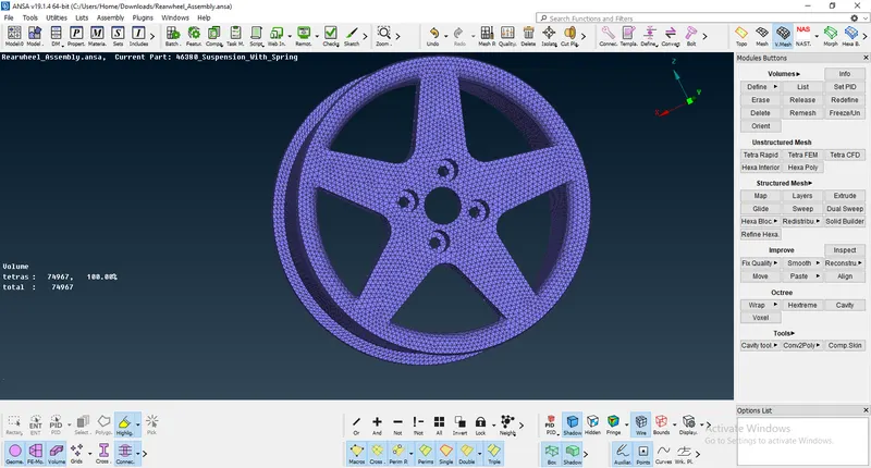
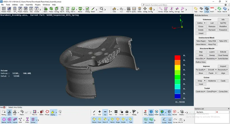
FIG.11 RIM VOLUME MESH
so, here we have done solid Tetrahedral mesh for TYRE and RIM as per given quaality criteria.
Next we can go with rest of the components with different quality criteria as given
STEERING KNUCKLE JOINT:
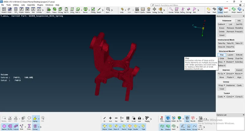
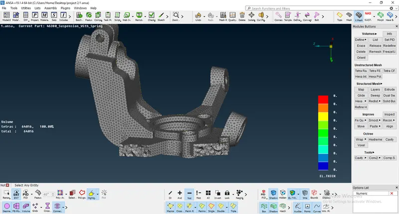
FIG 12. STEERING KNUCKLE JOINT
BASE JOINT
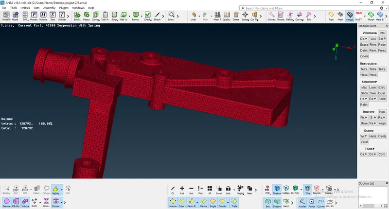
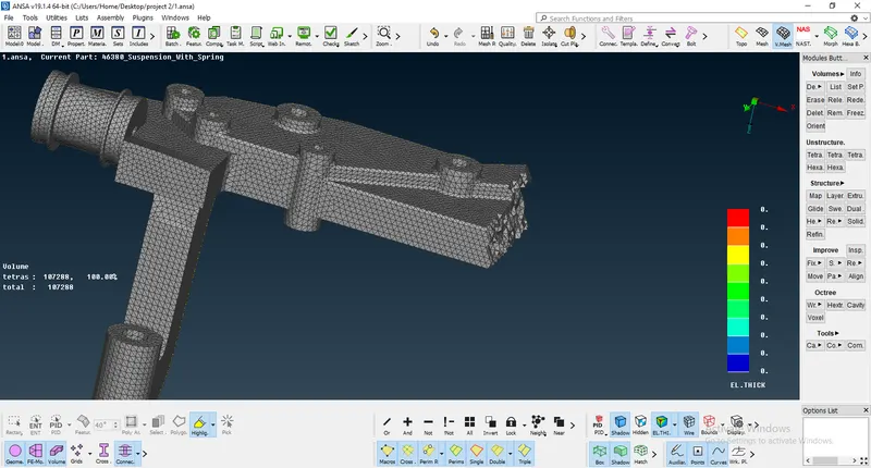
FIG.13 BASE JOINT
STSBILIZER BAR:
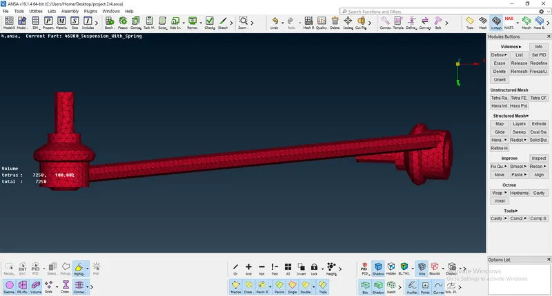
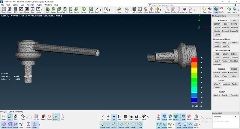
FIG 14. STSBILIZER BAR
UPPER STRUT MOUNT:
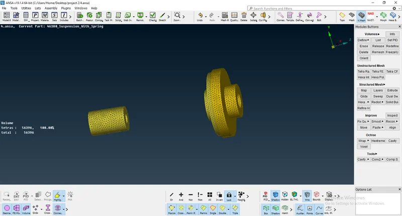
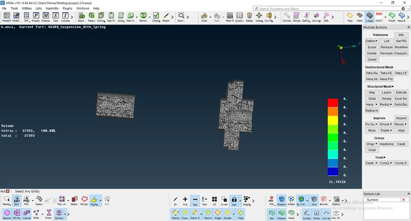
FIG 15. UPPER STRUT MOUNT
STRUT ASSEMBLY ROD:
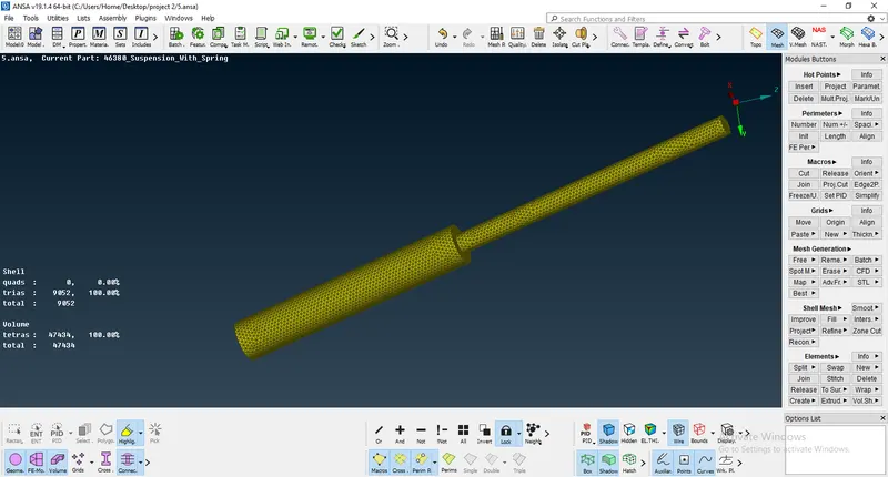
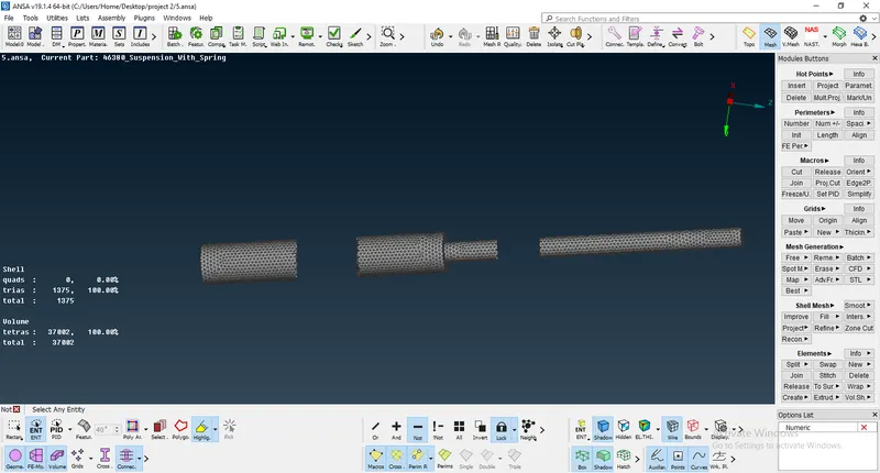
FIG 16. STRUT ASSEMBLY ROD
RACK AND PINION UNITS:
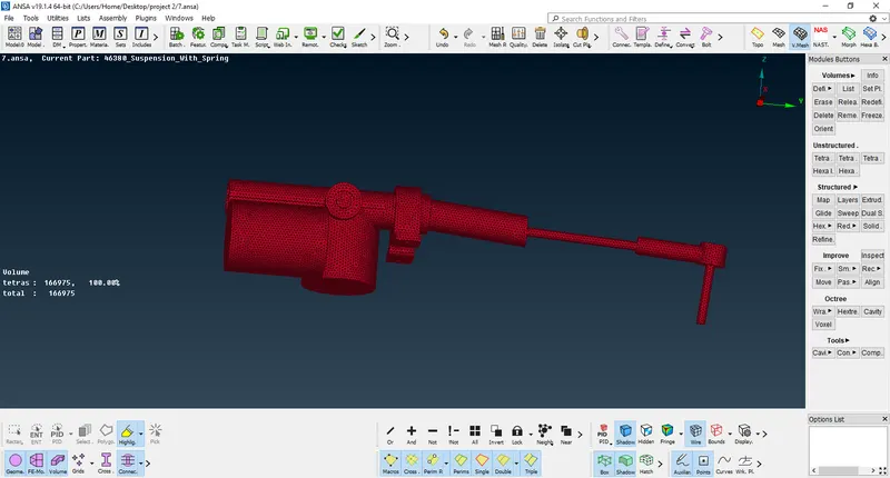
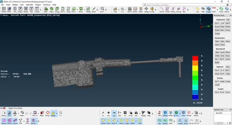
FIG 17. RACK AND PINION UNITS
JOINTS :
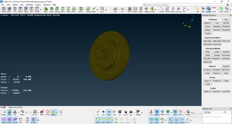
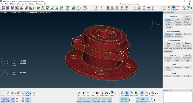
FIG 18.JOINTS
DISC STOPPER:
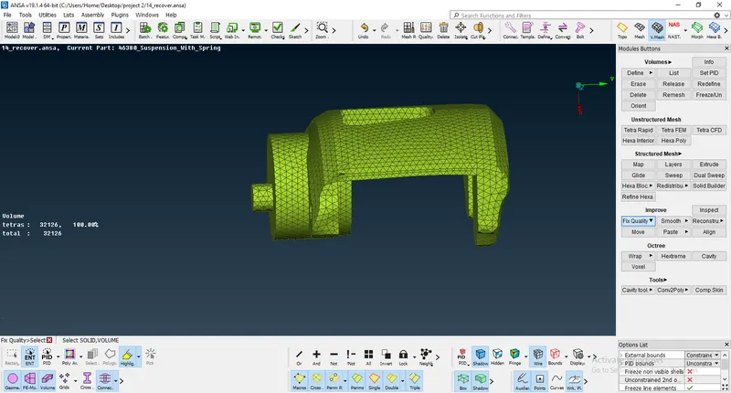
FIG 19. DISC STOPPER
COIL SPRING:
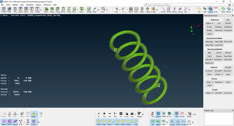
FIG 20. COIL SPRING
SWAY BAR:
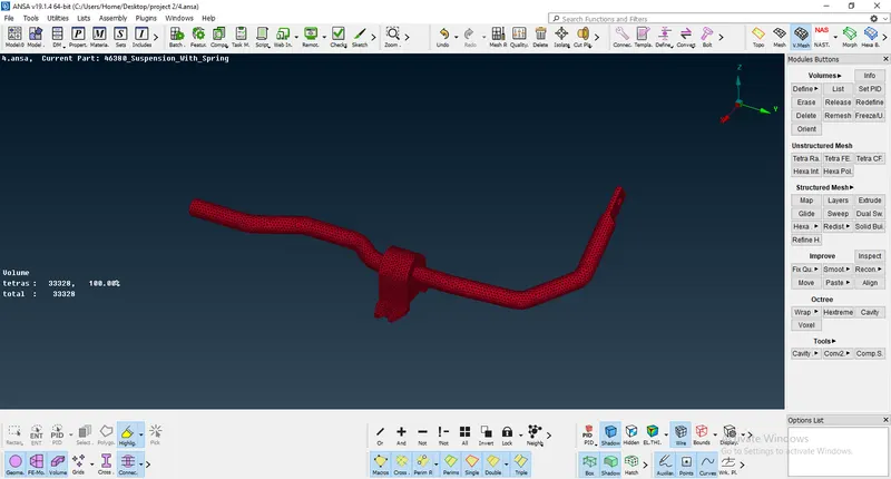
FIG 21. SWAY BAR
STEP 5: IMPROVE THE MESH FLOW WITH PROPER FEATURE CAPTURING:
Follow feature capturing in all areas, avoid failing elements and also remove tet collapse in the tetrahedral mesh
for shell mesh avoid trias falling on the feature lines and avoid rotational quads these will help us for good mesh flow.
STEP 6: CONNECTIONS REPRESENTATION
After completing the model we can go with connections
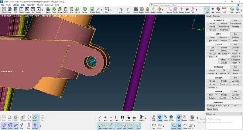
Here we have used rigid connections like spot weld, RBE2, RBE3, PBAR for connections
CLUSTER RBE2:
Here we have represented the bolt connectio using cluster RBE2 and joint using 2 noded RBE2
we can create using COG or selecting nodel also.
 '
'
FIG 22. CLUSTER RBE2
spring connection using cluster RBE2
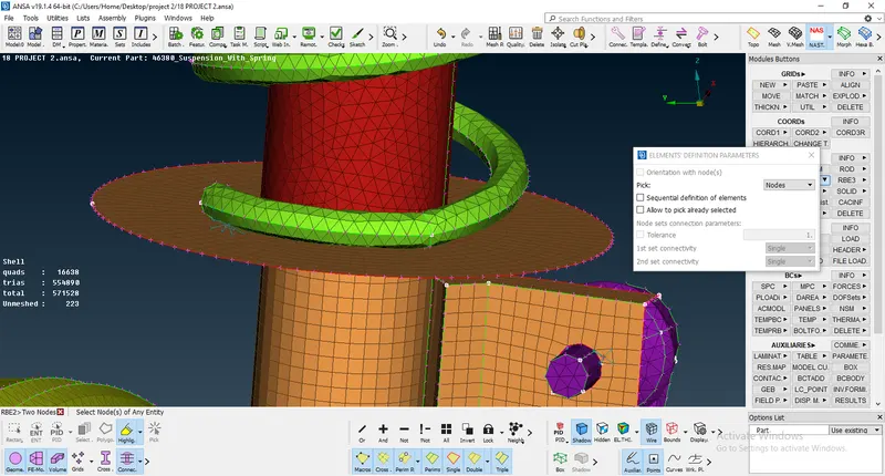
FIG 23. SPRING CONNECTION USING RBE2
cluster RBE2 and joined using 2 noded RBE2
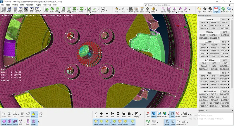
FIG 24. RBE2 CONNECTION WITH TWO NODED
2 noded RBE2
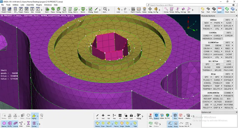
FIG 25. TWO NODED RBE2 CONNECTION
SPOT WELD CONNECTION:
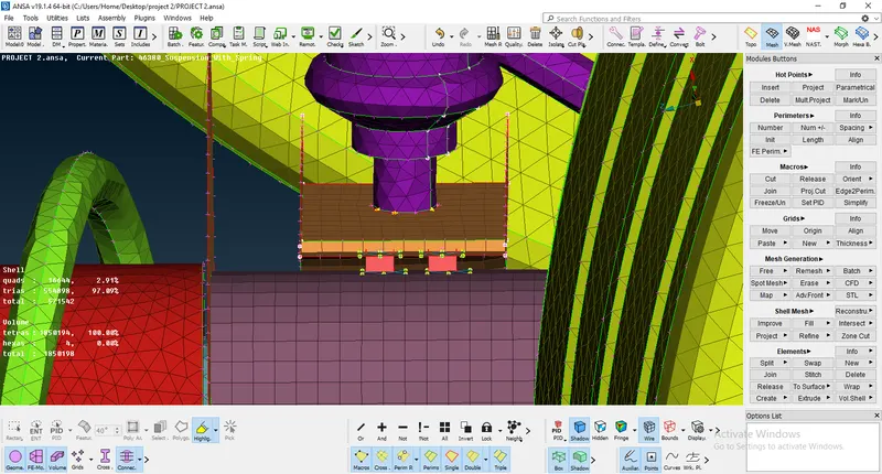
FIG25.1 SPOT WELD CONNECTION:
P BAR connection:
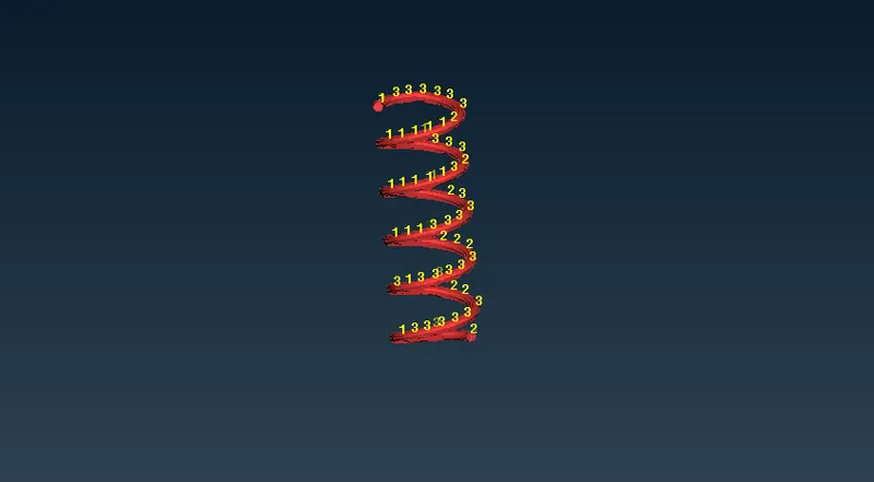
FIG 26. P BAR SPRING CONNECTION
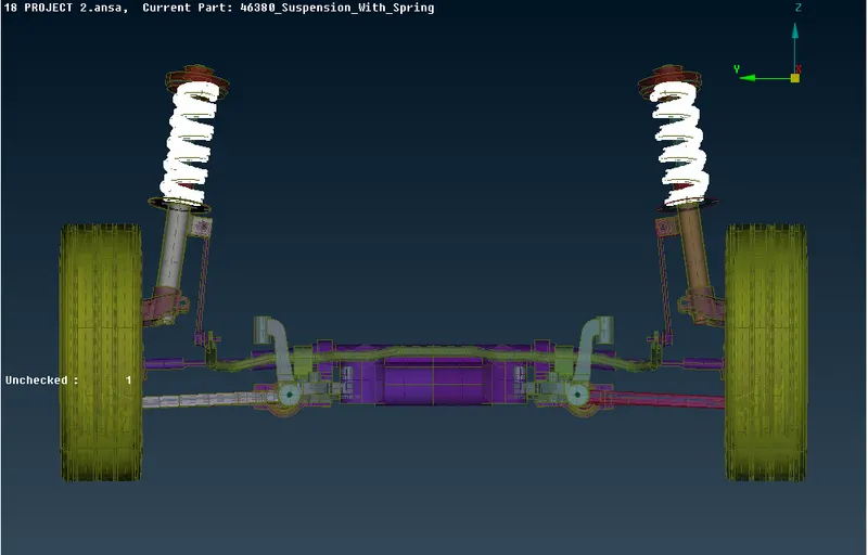
FIG 27. P BAR connection
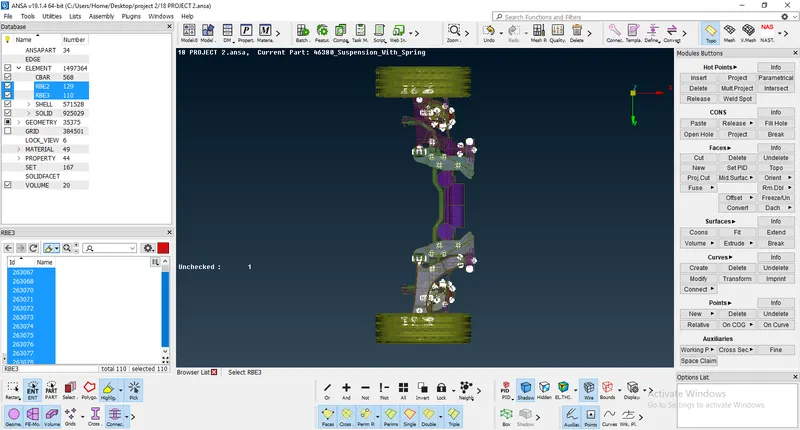
FIG 28. FULL CONNECTION REPRESENTATION VIEW
LEARNING OUTCOMES:
- LEARNED TO DO TOPOLOGY CLEANUO WITH NO ERRORS
- ASSIGNED SEPERATE PID'S FOR ALL THE COMPONENTS
- LEARNED DIFFERENT TYPES OF MIDSURFACE AND MESH TECHNIQUES
- LEARNED TO CAPTURE FEATURE PROPERLY
- LEARNED CONNECTIONS NEEDS AND PARAMETERS USED TO CONNECTION
CONCLUSION
In this project, did topological cleanup, I have generated midsurface and did volume tetrahedral mesh using options in TOOL, acheives proper mesh flow using reconstruct and smooth, Eliminated kinks and raised edges in tetra mesh, Successfully applied all given quality parameters for different components and eliminated off elements on the mesh and successfully deployed connections for the suspension assembly, finally preprocessing for the suspension assemly has been done using ansa tool.
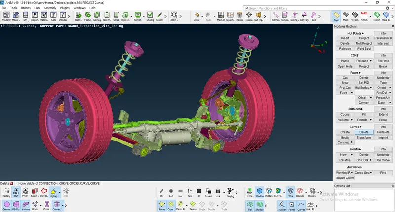
FIG 29. FINAL MODEL VIEW1
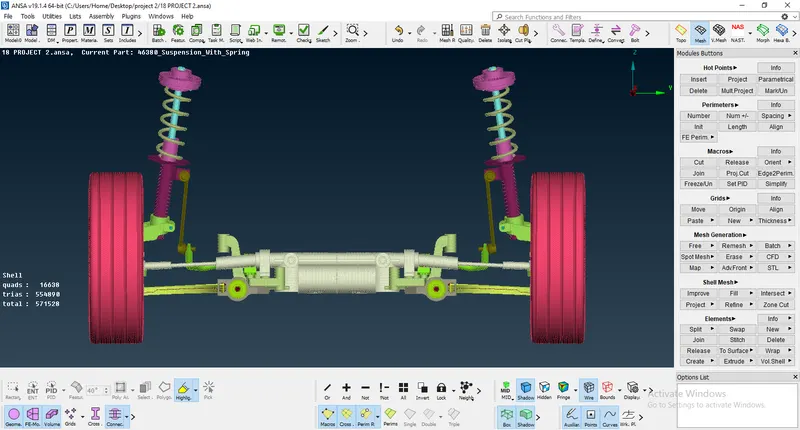
FIG 30. FINAL MODEL VIEW 2
DRIVE LINK: SUSPENSION ASSEMBLY