EXTRACTING MIDSURFACE AND MESHING FOR THE HOOD COMPONENT USING ANSA
OBJECTIVE: For the given component, check for the geometrical errors and mesh with the given element Quality criteria. After meshing the component the thickness has to be assigned.
QUALITY CRITERIA GIVEN:
|
S.No |
Quality Criteria |
Value |
|
1 |
Target/Average length |
5 |
|
2 |
Minimum Length |
2 |
|
3 |
Maximum Length |
7 |
|
4 |
Aspect |
3 |
|
5 |
Warpage |
15 |
|
6 |
Skewness |
45 |
|
7 |
Jacobian |
0.7 |
|
8 |
Minimum Quad Angle |
45 |
|
9 |
Maximum Quad Angle |
135 |
|
10 |
Minimum Tria Angle |
30 |
|
11 |
Maximum Tria Angle |
120 |
|
10 |
Tria Percentage |
15 |
PROCEDURE:
- IMPORT THE GIVEN HOOD COMPONENT
- CHECK FOR GEOMETRY
- EXTRACT THE MIDSURFACE
- MESH
- CLEANUP THE QUALITY CRITERIA
- ASSIGN THE THICKNESS
STEP1: IMPORT THE GIVEN HOOD COMPONENT
COMMAND: FILE-OPEN-CHOOSE FILE FOLDER (CTRL+O)
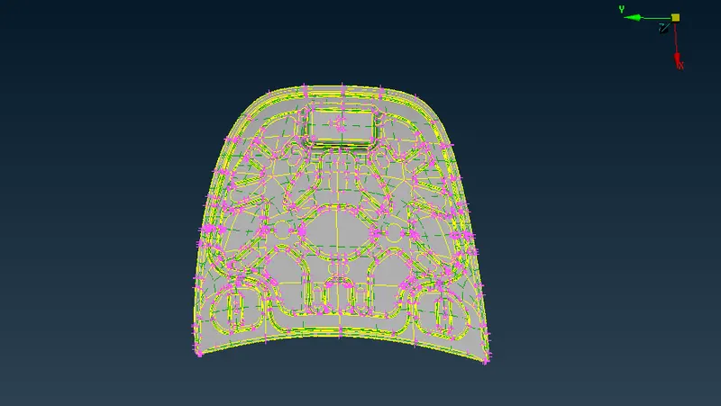
FIG1.1 GIVEN HOOD COMPONENT
After importing the model we should set proper PID's and delete the unwanted PID's, here we have Five different components so we can set PID's for each components. which are,
- INNER BODY EXTRACT
- OUTER BODY EXTRACT
- LATCH
- HINGE 1
- HINGE 2
STEP2: CHECK FOR GEOMETRY
After importing the geometry we should check for geometry issues
COMMAND: CHECKS-GEOMETRY-EXECUTE

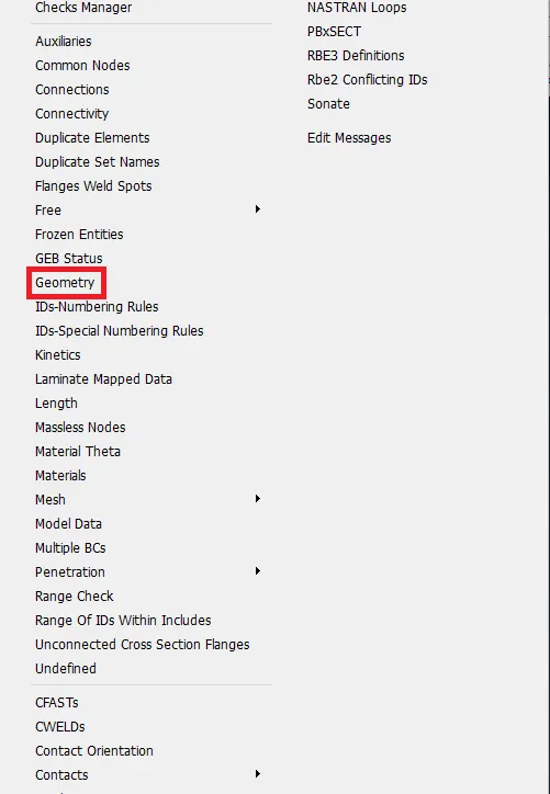
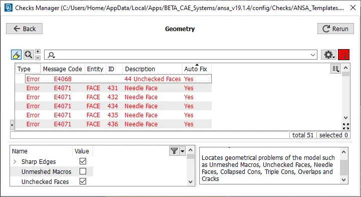
FIG 2.1 CHECKING GEOMETRY BEFORE CLEAN UP CHECKS
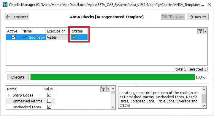
FIG 2.2 CHECKING GEOMETRY AFTER CLEANUP CHECKS
fix the issues using auto fix or we can fix it manually, fix all the issues until it reaches zero and status in green.
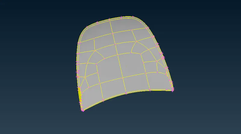
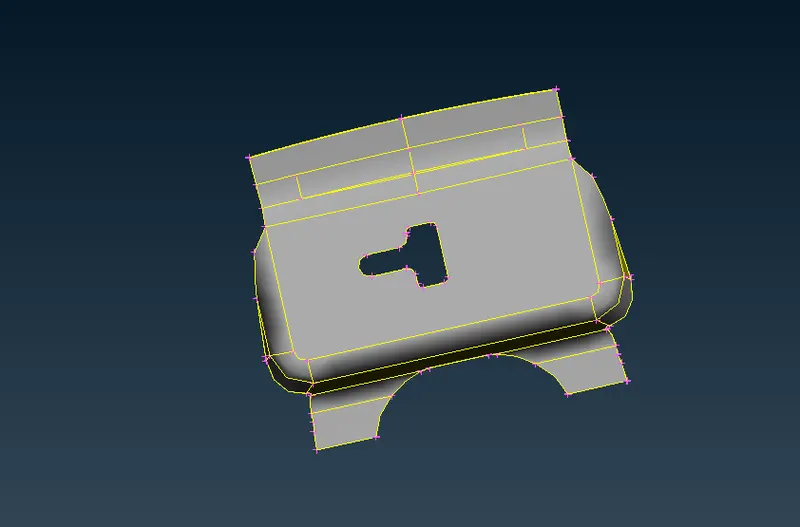
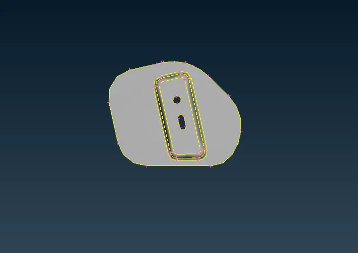
FIG 2.3 BEFORE CLEANUP GEOMETRY OUTER BODY, LATCH, HINGE
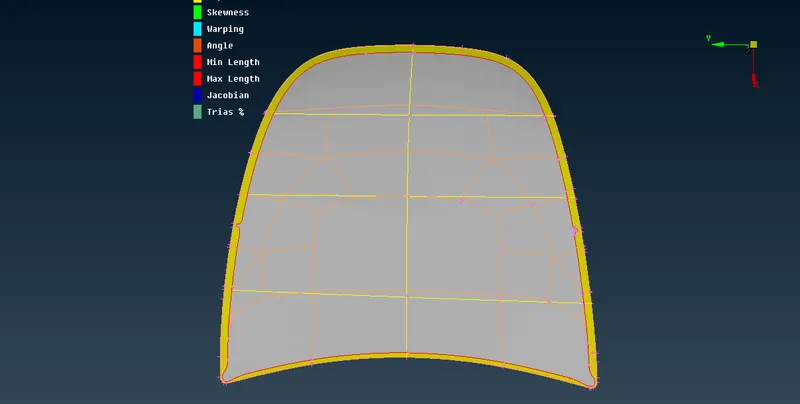
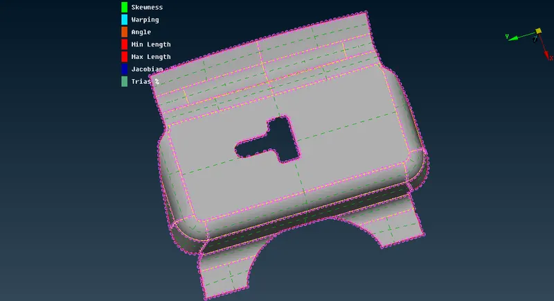
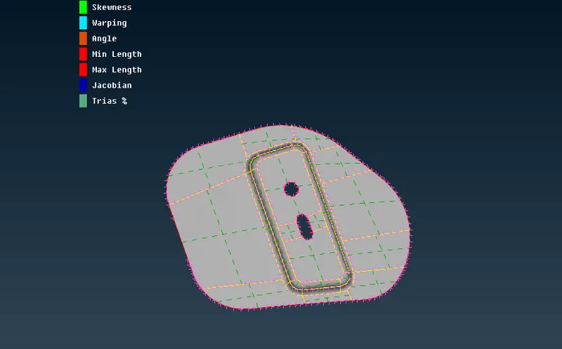
FIG 2.3 AFTER CLEANUP GEOMETRY OUTER BODY, LATCH , HINGE
STEP 3: EXTRACT MIDSURFACE
Before extracting the midsurface we shold measure the dimensions for each and every components for different directions.
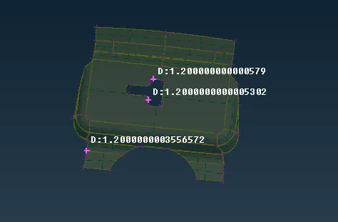
FIG3.1 MEASUREMENT ON LATCH (1.2)
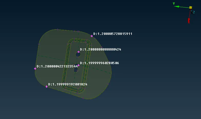
FIG3.2 MEASUREMENT ON HINGE(1.2)
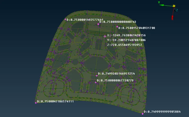
FIG3.3 MEASUREMENT ON INNER BODY EXTRACT(0.75)
here the Latch, Hinge1, Hinge2 are having 1.2 and outer and inner extract body having 0.75 thickness.
we can use the offset option to take the midsurface because of the complex geometry.
COMMAND: ON TOPO--FACES--OFFET-GIVE HALF OF THE THICKENESS OF THE MEASURED THICKNESS
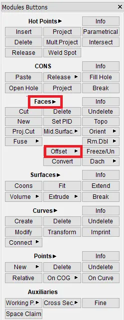
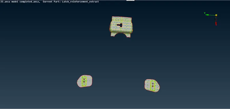
FIG3.4 MIDSURFACE ON LATCH, HINGE1, HINGE2
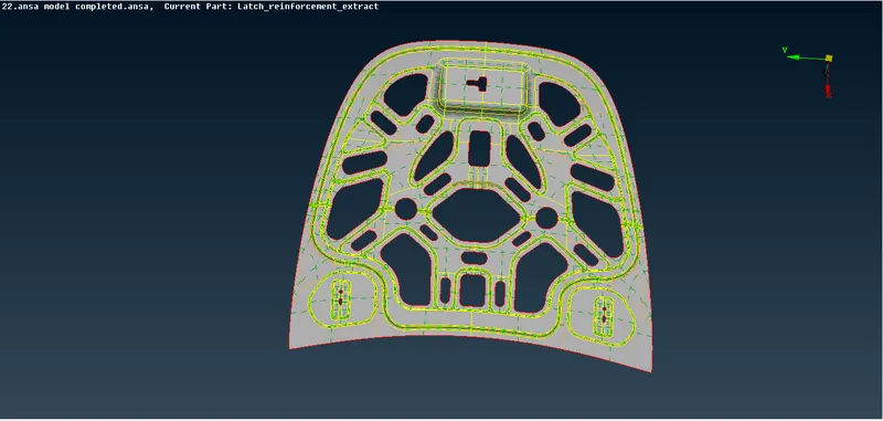
FIG3.5 MIDSURFACE ON INNER BODY EXTRACT
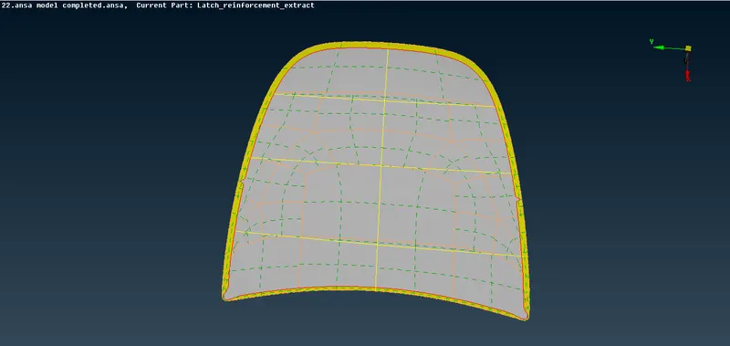
FIG3.6 MIDSURFACE ON OUTER BODY EXTRACT
STEP4: MESHING
Before going to mesh we need to fix the lengths for the component. And also need to apply the quality criteria for the mesh
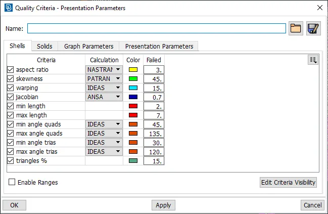
FIG 4.1 QUALITY CRITERIA
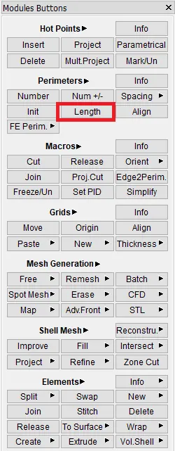
COMMAND: MESH--MESH GENERATION-- BEST
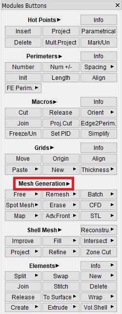
COMMAND: MESH--SHELL MESH-- RECONSTRUCT
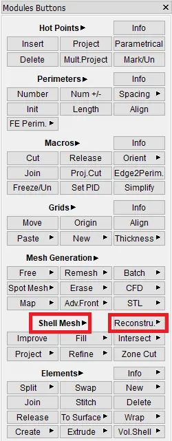
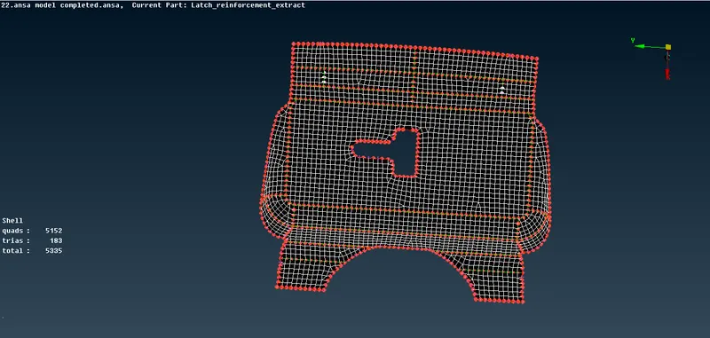
FIG4.2 MESH ON LATCH
STEP5: QUALITY CRITERIA
To clean up the quality we can use ELEMENTS option ie., split, join, swap etc and also smooth. by reconstructing the mesh we will acheive the good quality mesh.
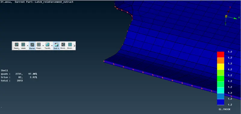
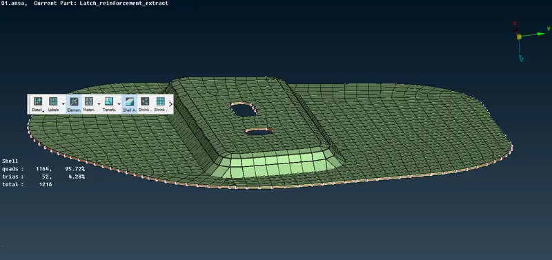
STEP6 : ASSIGNING THICKNESS:
we have to assign the material card as well as thickness for every components.
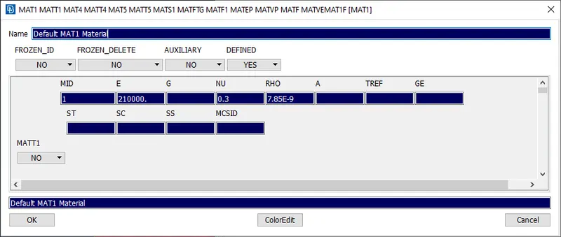
FIG6.1 ASSIGNING MATERIAL CARD
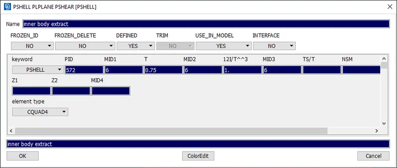
FIG6.2 ASSIGNING THICKNESS
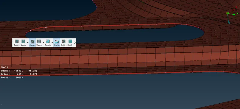
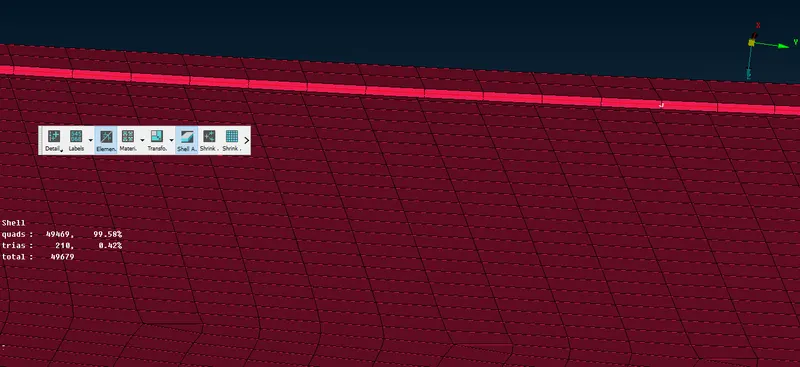
To see the thickness we assigned.
COMMAND: PROPERTIES- PRESENTATION PARAMETER- CHECK - SHELL AS SOLIDS

CONCLUSION:
By the following procedure the component has been meshed with no off elements with proper flow.
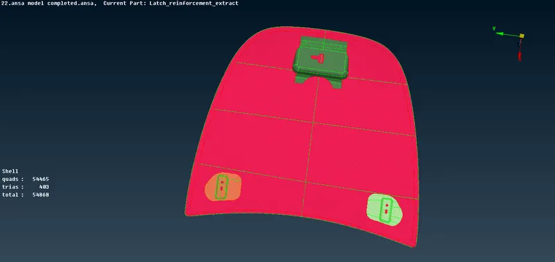
MESH ON OUTER BODY, HINGES AND LATCH
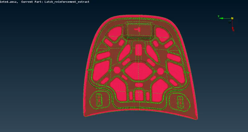
FINAL MESHED COMPONENTS
LEARNING OUTCOMES:
Lean how to extract the midsurface.
In this method we learn how to mesh with proper flow.
And cleanup the quality criteria.
And assigining the thickess for the component.
DRIVE LINK
https://drive.google.com/file/d/1twURHVKcq7-26mW0FT_kp8xu7lzlyuE8/view?usp=sharing