BATCH MESHING AND ASSIGN NON-LINEAR MATERIAL PROPERTY ON HYPERMESH
BATCH MESHING AND ASSIGN NON-LINEAR MATERIAL PROPERTY
OBJECTIVE:
Perform Batch-meshing on the following components with the given criteria and assign the non-linear material property Steel to them.
Use Radioss profile for assigning the material properties
Quality Criteria:-
S.N Quality Criteria Value
1 Aspect Ratio 5
2 Skewness 45
3 Warping 15
4 Taper 0.5
5 Min. Length 2mm
6 Max. Length 8mm
7 Min angle Quad 45
8 Max angle Quad 135
9 Min angle Tria 20
10 Max angle Tria 120
10 Tria % 10
Target Element Length = 5mm
PROCEDURE:
Batchmeshing is meshing process in which perform midsurfsce, geometry clesnup, meshing the component with given quality criteria automatically.
Imort the given models in hypermesh.
Delete the solids if any on the models.
command: Delete-Select solids-Delete entity.
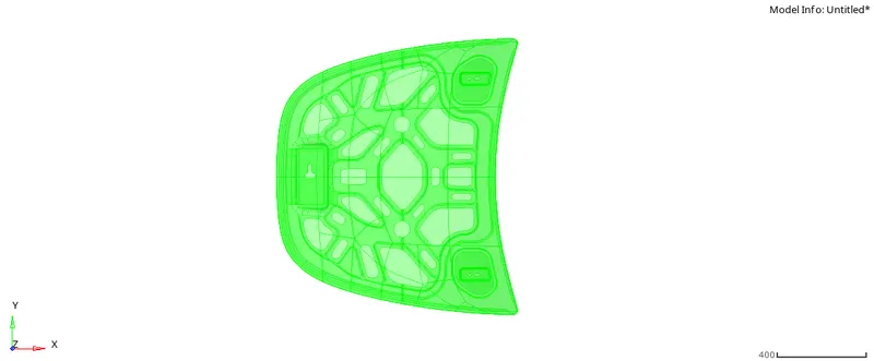
FIG 1 SOLID COMPONENT
components are need to mesh separetely, hece need to hide all the components except the component going to mesh.
In batch meshing we need to create a parameter file and criteria file by our own. before that we need to create the duplicate component if needed, because while batchmeshing the parent geometry will be deleted while creating the midsurface.
The parameter and criteria files should be saved in the files.
1.HOOD COMPONENT:
Then go for batch meshing. INNER EXTRACT BODY.
command 2D-automesh- batch mesh/QI optimize-browse the saved parameter and criteria file- select the surface- mesh.
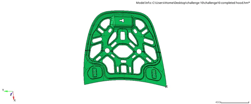
FIG1.1 BATCH MESH ON INNER EXTRACT BODY
After creating the mesh select the parent geometry and verify the midsurface created.
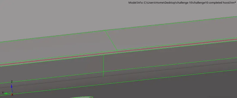
FIG1.2 MIDSURFACE OF INNER EXTRACT BODY
THen create the material card fo the components for non-linear material.
command: Tab bar- left click- create -material.
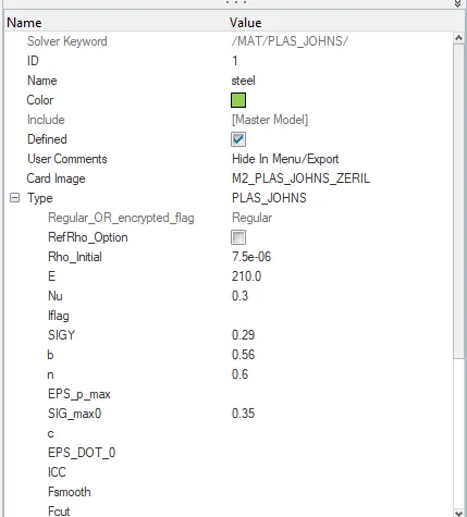
FIG1.3 MATERIAL CARD FOR HOOD COMPONENT (STEEL)
Then create a property for each components.
command: Tab bar- leftclick- create-property.
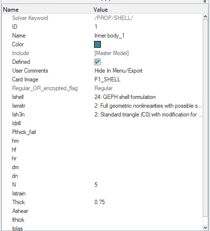
FIG1.4 PROPERTY CARD FOR INNER EXTRACT BODY COMPONENT
ASSIGN THE MATERIAL AND PROPERTY FOR THE INNER EXTRACT BODY.
Then go for batch meshing. OUTER EXTRACT BODY.
command 2D-automesh- batch mesh/QI optimize-browse the saved parameter and criteria file- select the surface- mesh.
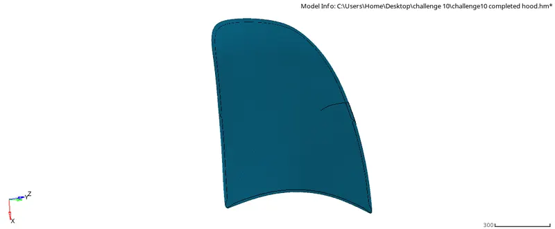
FIG1.5 BATCH MESH ON OUTER EXTRACT BODY
After creating the mesh select the parent geometry and verify the midsurface created.
Then create a property for each components.
command: Tab bar- leftclick- create-property.
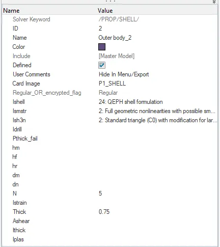
FIG1.6 PROPERTY CARD FOR OUTER EXTRACT BODY COMPONENT
ASSIGN THE MATERIAL AND PROPERTY FOR THE OUTER EXTRACT BODY.
Then go for batch meshing. HINGE_REINFORCEMENT EXTRACT BODY 1
command 2D-automesh- batch mesh/QI optimize-browse the saved parameter and criteria file- select the surface- mesh.
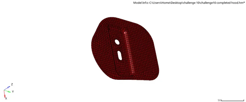
FIG1.7 BATCH MESH ON HINGE 1
After creating the mesh select the parent geometry and verify the midsurface created.
Then create a property for each components.
command: Tab bar- leftclick- create-property.
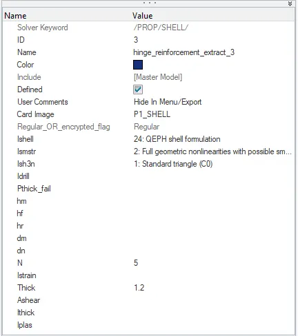
FIG1.8 PROPERTY CARD FOR HINGE 1
ASSIGN THE MATERIAL AND PROPERTY FOR THE HINGE_REINFORCEMENT EXTRACT BODY 1.
Then go for batch meshing. HINGE_REINFORCEMENT EXTRACT BODY 2
command 2D-automesh- batch mesh/QI optimize-browse the saved parameter and criteria file- select the surface- mesh.
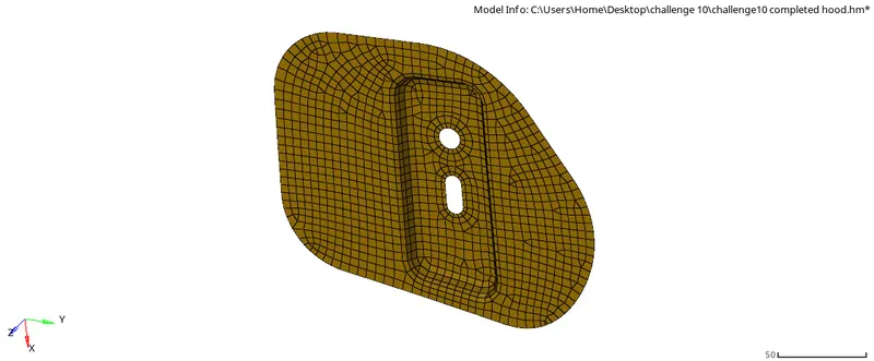
FIG1.9 BATCH MESH ON HINGE 2
After creating the mesh select the parent geometry and verify the midsurface created.
Then create a property for each components.
command: Tab bar- leftclick- create-property.
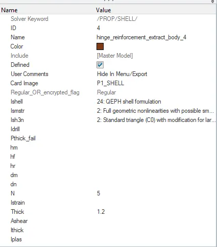
FIG1.10 PROPERTY CARD FOR HINGE 2
ASSIGN THE MATERIAL AND PROPERTY FOR THE HINGE_REINFORCEMENT EXTRACT BODY 2
Then go for batch meshing. LATCH_REINFORCEMENT EXTRACT BODY.
command 2D-automesh- batch mesh/QI optimize-browse the saved parameter and criteria file- select the surface- mesh.
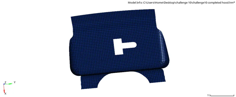
FIG1.11 BATCH MESH ON LATCH
After creating the mesh select the parent geometry and verify the midsurface created.
Then create a property for each components.
command: Tab bar- leftclick- create-property.
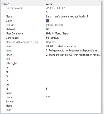
FIG1.12 PROPERTY CARD FOR LATCH
ASSIGN THE MATERIAL AND PROPERTY FOR THE LATCH_REINFORCEMENT EXTRACT BODY.
2.FENDER COMPONENT:
Quality Criteria:-
S.N Quality Criteria Value
1 Aspect Ratio 5
2 Skewness 45
3 Warping 15
4 Taper 0.5
5 Min. Length 2mm
6 Max. Length 8mm
7 Min angle Quad 45
8 Max angle Quad 135
9 Min angle Tria 20
10 Max angle Tria 120
10 Tria % 10
Target Element Length = 5mm
Delete the solids if any on the models.
command: Delete-Select solids-Delete entity.
Then go for batch meshing. FENDER_BODY component.
command 2D-automesh- batch mesh/QI optimize-browse the saved parameter and criteria file- select the surface- mesh.
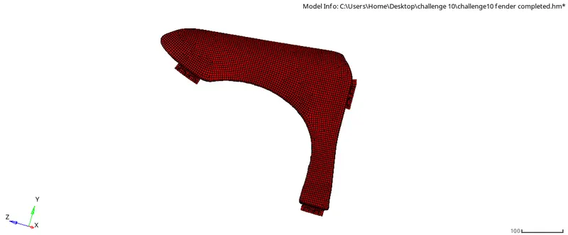
FIG 2.1 BATCH MESH ON FENDER
Then create the material card for the components for non-linear material.
command: Tab bar- left click- create -material.
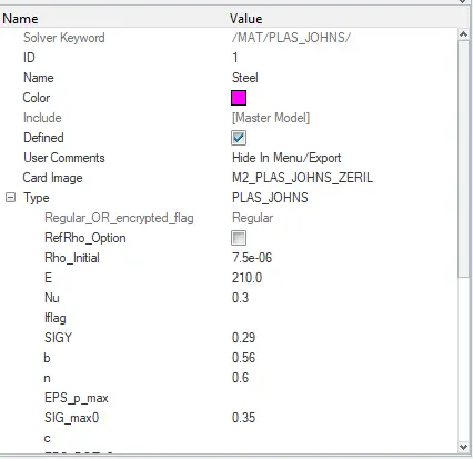
FIG 2.2 MATERIAL CARD FOR FENDER
After creating the mesh select the parent geometry and verify the midsurface created.
Then create a property for each components.
command: Tab bar- leftclick- create-property.
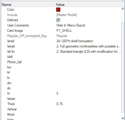
FIG 2.3 PROPERTY CARD FOR FENDER
ASSIGN THE MATERIAL AND PROPERTY FOR THE FENDER.
3. DISADVANTAGES WHEN USING BATCH MESH:
Wile creating the batch mesh its created the midsurface without capturing the surface properly, it will created the extra surfaces as shown in the below figure.
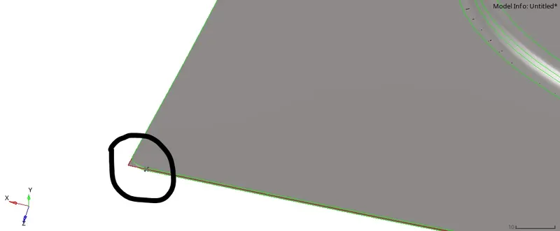
FIG 3.1 UNEVEN MIDSURFACE CREATED ON INNER EXTRACT BODY
And also it does not capture the holes as well.
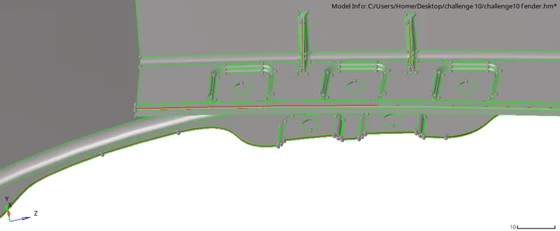
FIG 3.2 PARENT GEOMETRY OF FENDER COMPONENT
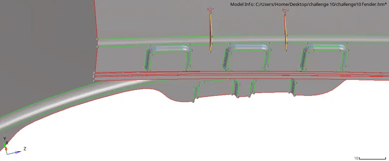
FIG 3.2.1 MIDSURFACE FENDER COMPONENT
Minimum lengths are failing on some areas.
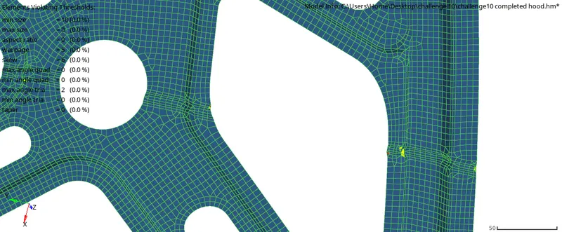
FIG3.3 INNER EXTRACT QUALITY INDEX
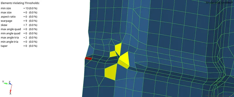
FIG3.3.1 INNER EXTRACT QUALITY INDEX ELEMENTS FAILING
And it created some free edges on the surfaces center. the topology cleanup was not good enough.
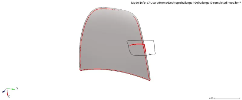
FIG 3.4 FREE EDGES ON OUTER EXTRACT BODY
More trias formations and also not capturing the features properly
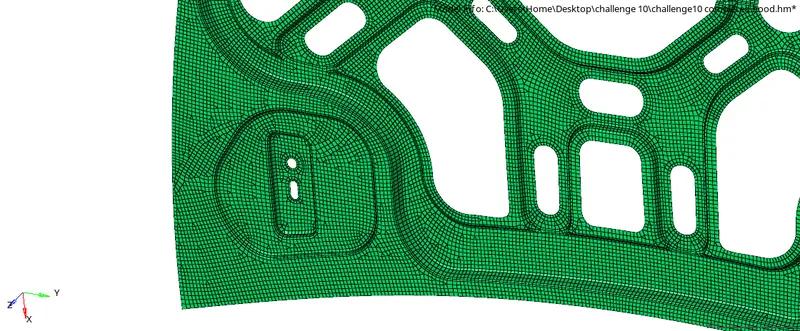
FIG 3.5 INNER BODY EXTRACT MORE TRIAS FALLING ON EDGES AND NOT PROPER MESH FLOW
CONCLUSION:
Learned about how to generate the batch mesh and how it is useful, for the complex geometry it will create more issues on quality side.
And also learned about how to create a material and property card for Non-Linear materials.
For meshing the complex geometry we need to remesh using manual mesh for 100% quality.
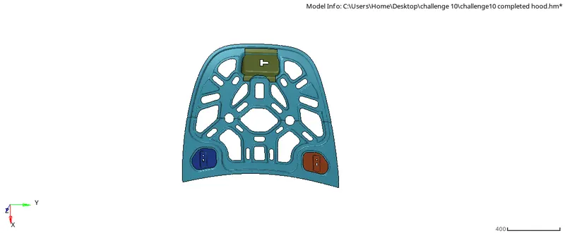
FINAL component hood
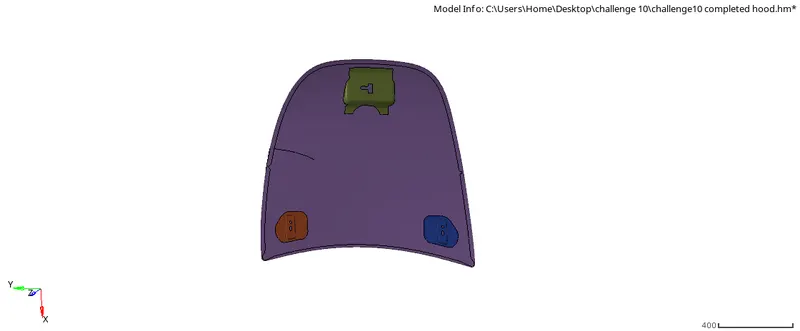
FINAL component hood.1
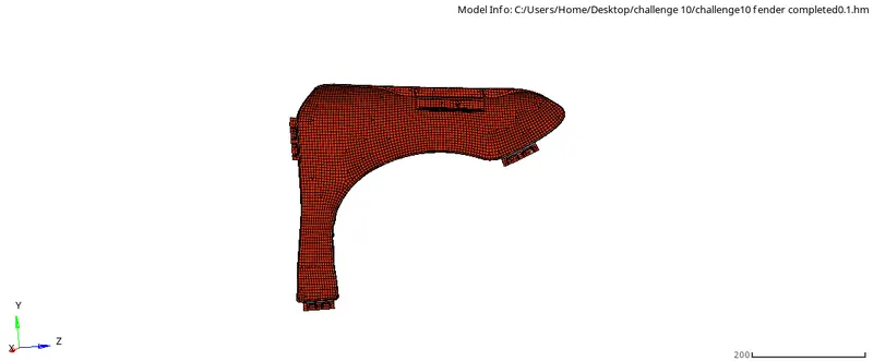
FINAL component FENDER