CREATING ID ELEMENT ON HYPERMESH
CREATING 1D ELEMENTS ON GIVEN COMPONENT WITH GIVEN CROSS-SECTION AND DOF
Objective :
To create a given component on given component with given cross-section and DOF
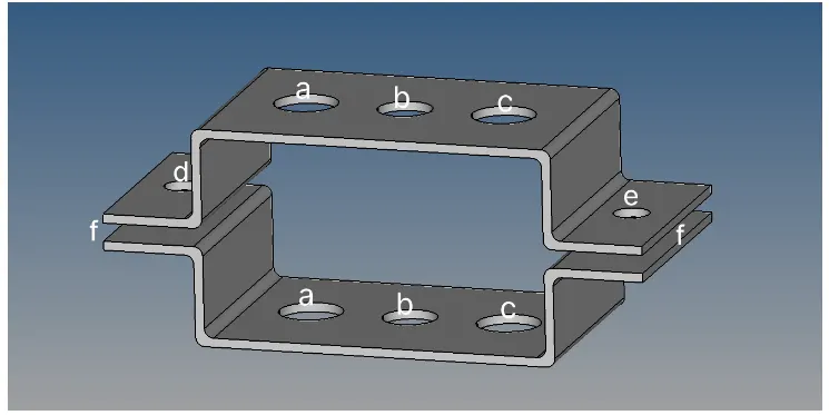
Theory :
1) Hyperworks - Hyperworks is a complete CAE software made by Altair engineering. It consist all the modULES of the CAE ie., modelin, meshing and solver. It is a complete package of finite element procedure.Preprocessing,Solving and Postprocessing can be done using hyperworks.Other than hypermesh, hyperworks includes OptiStruct,RADIOSS,Motionview,Motionsolve,FEKO etc.,
2) Hypermesh- Hypermesh is an inbuilt meshing software which coms along with hyperworks.It is a meshig tool.It can be used to model siple geometries,and its most important function is meshing.Meshing is an important process in finite element method.The accuracy of the solution depend on the type of mesh you choose and the complexity of the problem.
3) Finite Element Analysis (FEA)- The proces of dividing or discretizing our geometry into finite nodes and elements and solving it for stress and strains
4)Meshing- The particular process of discretizing FEA elemnt is meshing.
5) Rigids-Rigids are known as RBE2 elements.They have infinte stiffness.They never bends,rotate and move.Only the nodes can be moved in rigids.In RBE2, the load distribution is uniform irrespective of the position from the load.
6)RBE3-In RBE3, the load distribution is depends on the distance from the load. Load distribution is more on the nodes closer to the node.
7) Rods-Rods are used for compression and tension.But sometimes they used as rotation as well(limited).
8) Bars-In bars, all the 8 dots are usd for symmetrical section.
9) Beams- Beams are simiar to bars but aso used for assymetrical section also.
Specifications :
a) Rod element -With only translational and RBE2 link
Cross section BOX dimensions a= 12mm
b= 10mm
Thickness t= 0.75 mm
b) Beam element - With all DOF and RBE3 link
Cross section I section Dimensions a= 8mm
b= 10mm
c= 8.5 mm
Thickness T1 = 0.75 mm
T2 = 0.6 mm
T3= 0.6 mm
c) Bar Element -With only x and y DOF links and RBE3 link
Cross section CROSS Dimensions D1= 5 mm
D2= 1.2 mm
D3=10 mm
D4=1.2mm
d) & e).apply the mass of mgnitude 10 with RBE2 link
f)Join the given two components with Spring elements
PROCEDURE :
I. Importing geometry :
File-Import-Geometry-Select file-Import
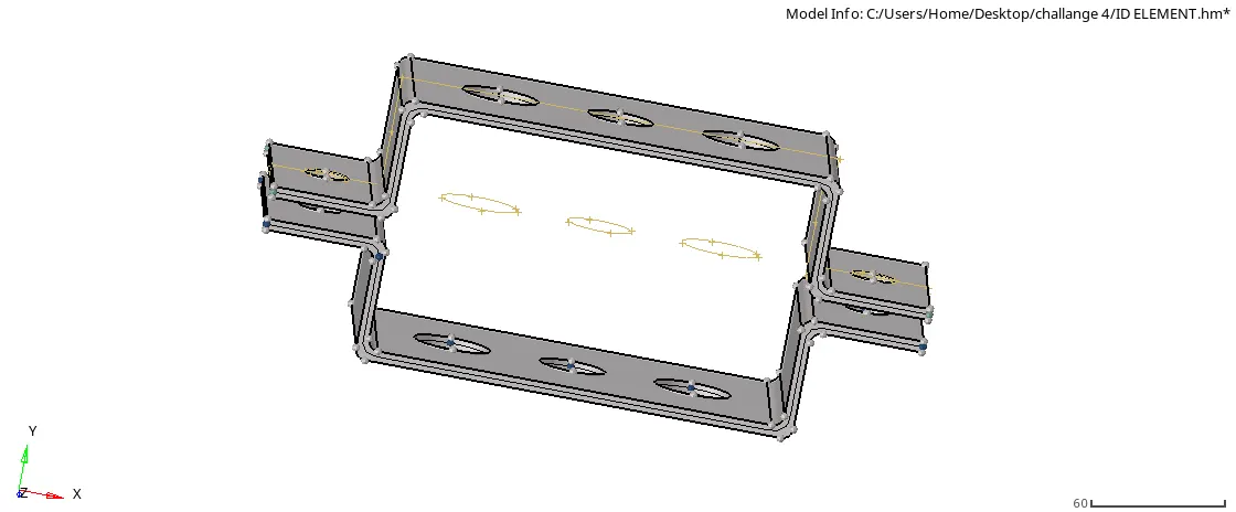
Fig 1.1 importing geometry
II. Extracting midsurface and deleting solid part
Step 1: Extracting midsurface
Geometry-midsurface-select the surface-extraxct
Rename component:Bracket_1
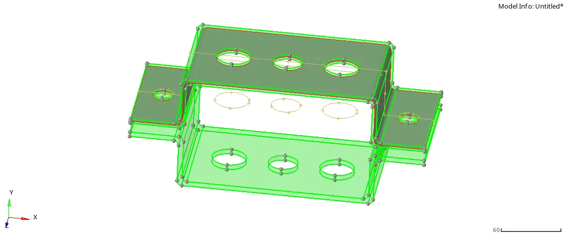
fig 2.1 creating mid surface
Step 2:Create new component (Right click component and create)
Rename: Bracket_2
Step 3:Delete solid part and wireframe
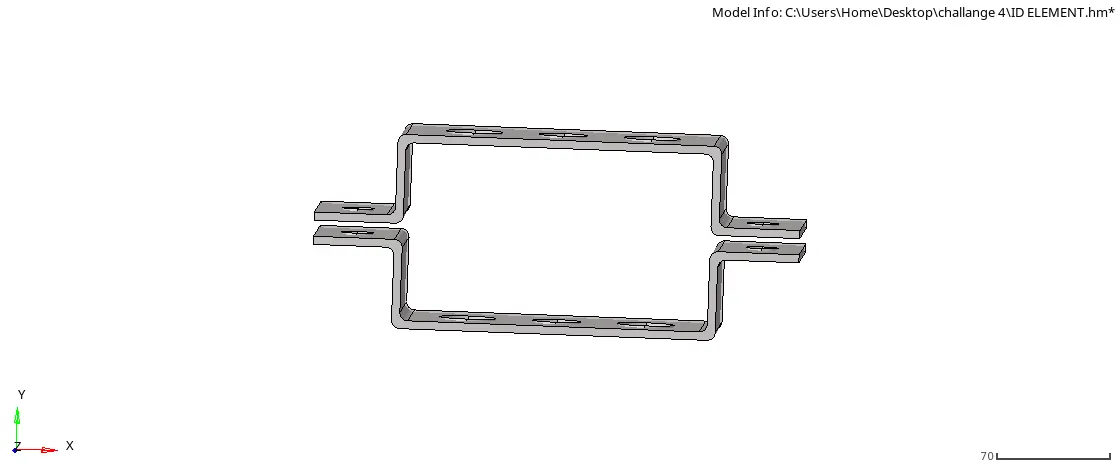
fig 2.2 deleting wire frame
Step 4: Move one midsurface to Bracket_2
Tool-Organise-select surface-give dest component to Bracket_2
Step 5:Changing colour
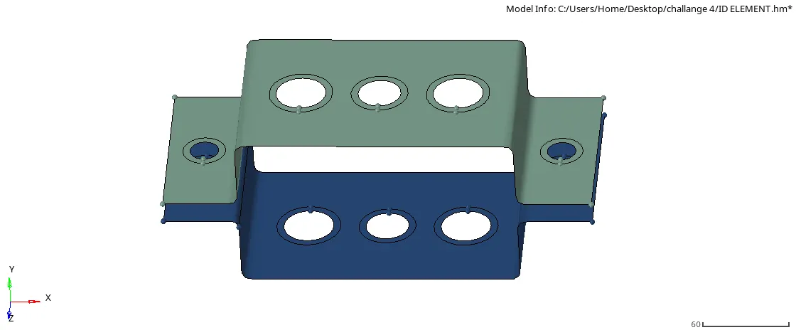
fig 2.3 changing colour
III. Meshing Brackets:
Step 1:Creating washer split
Geometry-Quick edit-give offset value=5 (Select the lines)
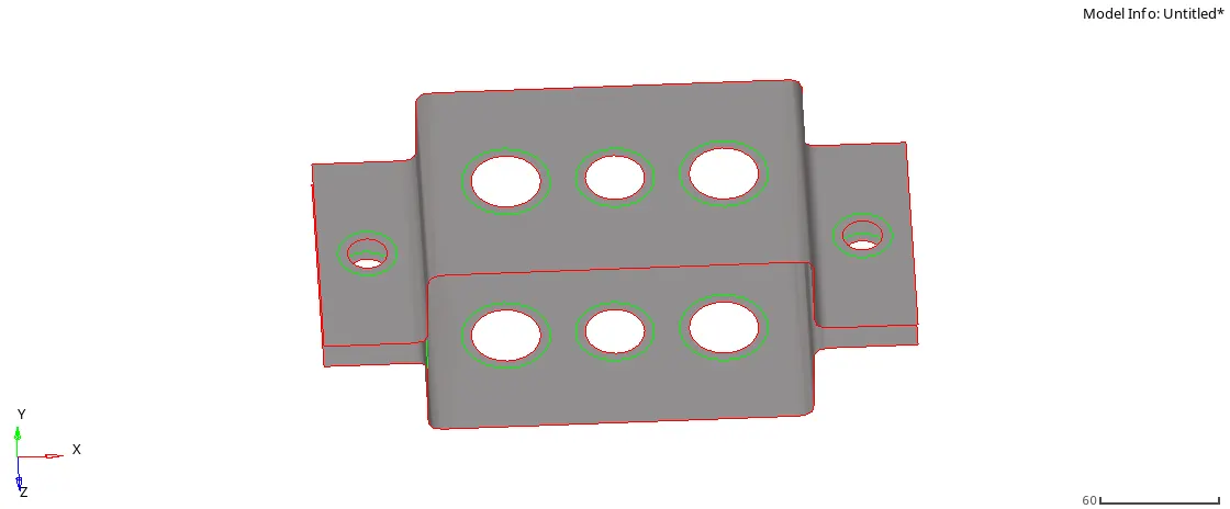
fig 3.1 creating washer nut
Step2:Meshing each bracket
2D-automesh-Select the surface-give element size = 8 mesh
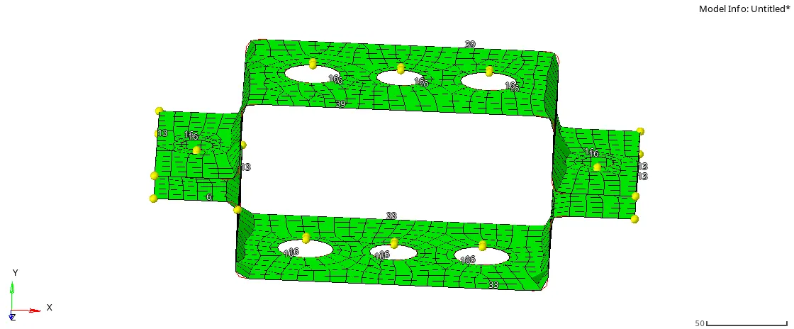
fig 3.2 meshing brackets
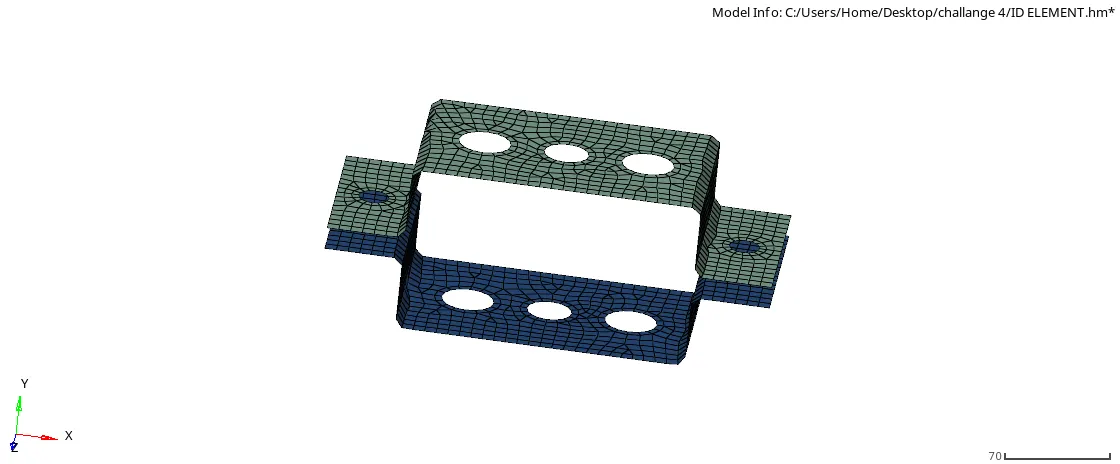
fig 3.3 meshed brackets
IV. Creating material:
(Right click on the model-tree ) create-material
Give material name as Steel
Give E=210000, Nu=0.3
V. Creating properties
(Right click on the model-tree ) create-property
We have to create properties for Bracket_1, Bracket_2, Rods, Beam, Bar aad spring
Give card image based on the property as given below:
| SERIAL NO | PROPERTY | CARD IMAGE |
| 1 | Bracket_1 | PSHELL |
| 2 | Bracket_2 | PSHELL |
| 3 | Rod | PROD |
| 4 | Beam | PBEAM |
| 5 | Bar | PBAR |
| 6 | Spring | PBUSH |
VI. Creating rod, beam, bar and mass elements:
a) Creating rod
Step 1:Creating RBE2 link
1D-rigids-select nodes-Uncheck-'dof1','dof2','dof3'-create
Step 2:Creating rod
1D-rods-select nodes-give property='Rod'
b) Creating beam
Step 1:Creating RBE3 link
1D-rbe3-select nodes- Uncheck all the dofs-create
Step 2: Creating beam
1D-BAR-select codes-Give property=Beam and element type='CBEAM'-give orientation
c) Creating bar
Step 1:Creating RBE3 link
1D-rbe3-select nodes- Uncheck-'dof1','dof2','dof4','dof5'
Step2: Creating bar
1D-BAR-select codes-Give property=Bar and element type='CBAR'-give orientation
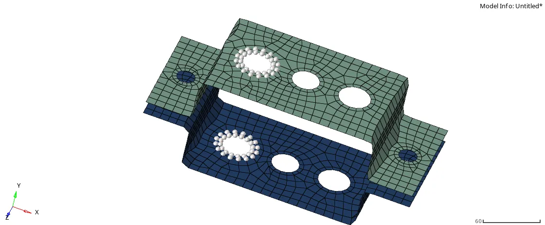
fig 6.1 creating RBE2 using nodes
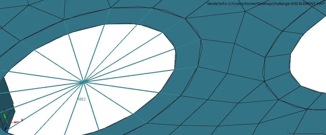
fig 6.2 RBE2 element
VIII. Crating cross-section
1D-Hyperbeam-select 'standard section'(from left options)-Select 'HYPERBEAM'(from standard section library0-create
a) Creating box cross section
a=12mm
dimension b= 10mm
thickness t=0.75mm
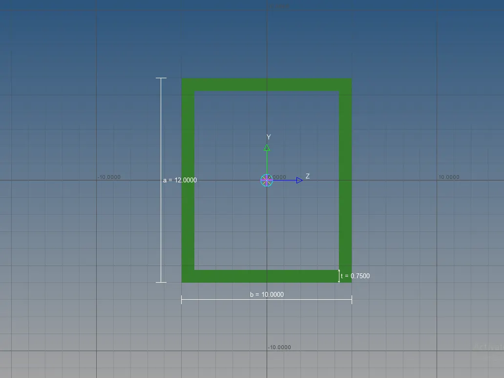
Fig 8.1 creating box cross section (ROD ELEMENT)
b) Creating I section
Dimensions a= 8mm
b=10mm
c=8.5 mm
Thickness t1=0.75 mm
t2=0.6mm
t3=0.6mm
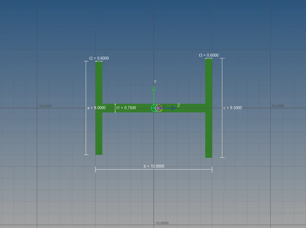
fig 8.2 creating I section(BEAM ELEMENT)
c) Creating cross section
Dimensions DIM1= 5mm
Thickness DIM2 =1.2mm
Dimensions DIM3= 10mm
Thickness DIM4=1.2mm
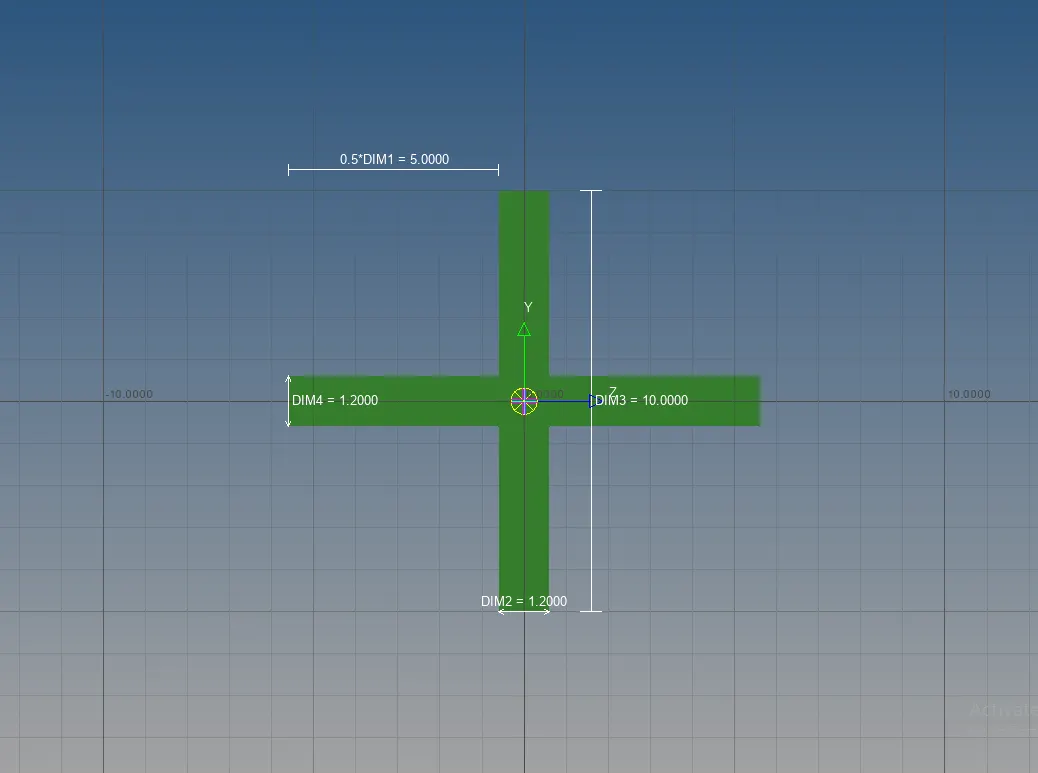
fig 8.3 creating cross section (BAR ELEMENT)
IX. Assigning cross-section to components
Select components one by one -Specify the correct beam section for each.
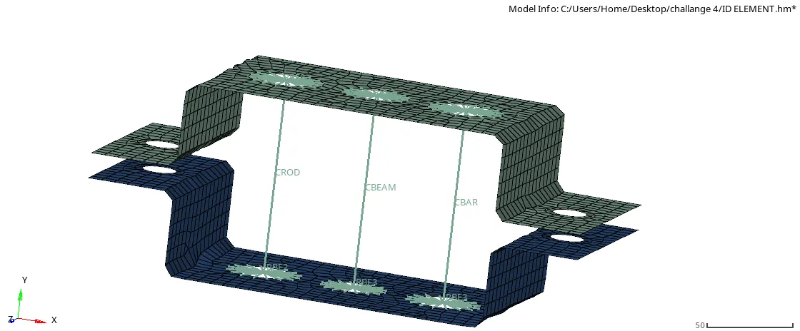
fig 9.1 Assigning cross section to componrnts
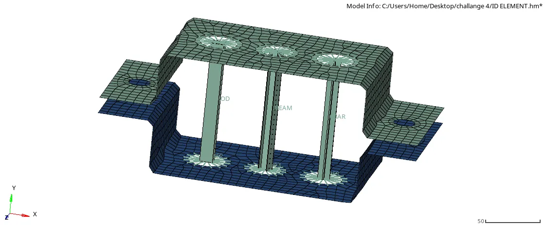
fig 9.2 changing traditional element to detailed element
Step 1:Creating RBE2 link
1D-rigids-select nodes-create
Step 2: Creating masses
1d-masses-Give magnitude='10'-Give element type='CMASS1'-Give property='bracket_1' or 'bracket_2'-create
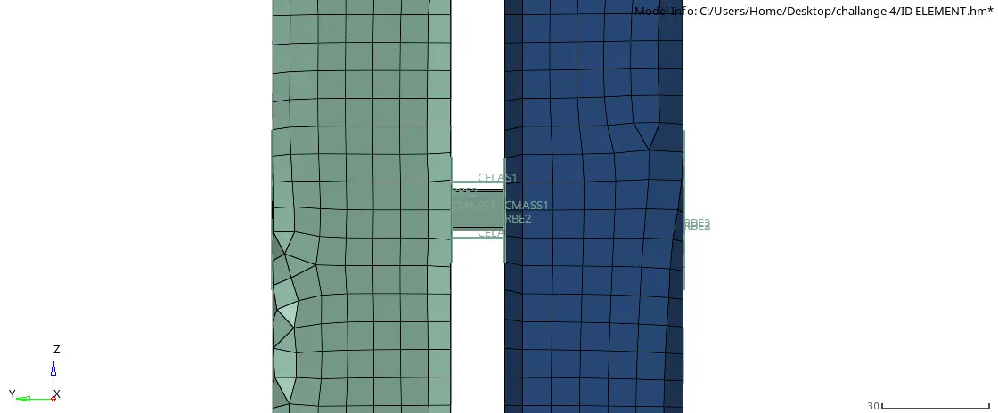 fig 9.1 Assigning cross section to componrnts
fig 9.3 generating masses(C MASS1)
F.Creatings springs
1D-SPRINGS-select the nodes-Give property='spring and element type'='CELAS1'
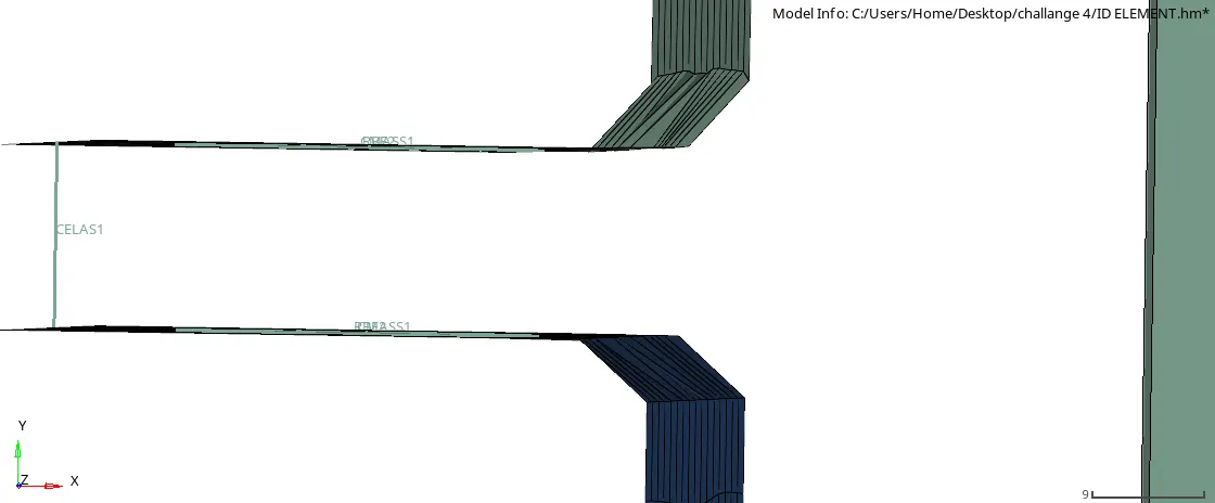
fig 9.4 CREATING SPRIGS
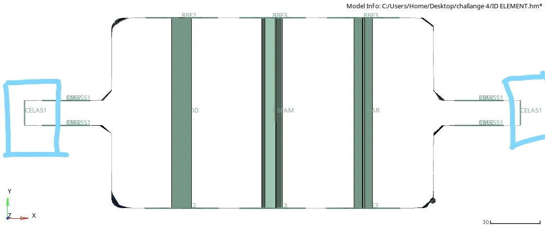
fig 9.5 BOTH SIDE SPRNGS
RESULT :
1) The geometry was imported and meshed.
2) ID elements were created on the given component with given cross section and DOF.
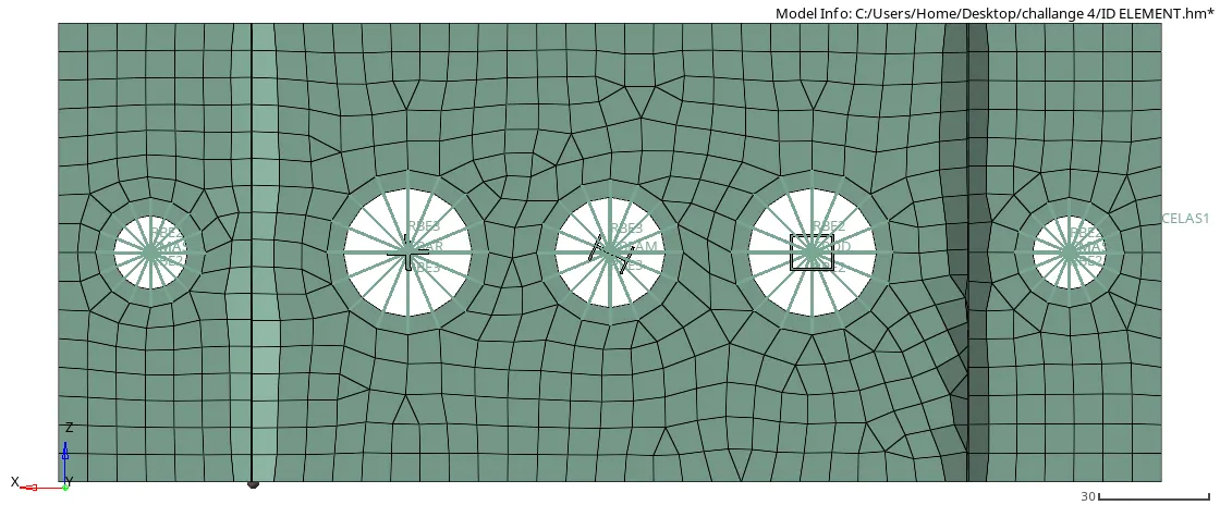
FINAL MESHED AND 1D ELEMENT TOP VIEW
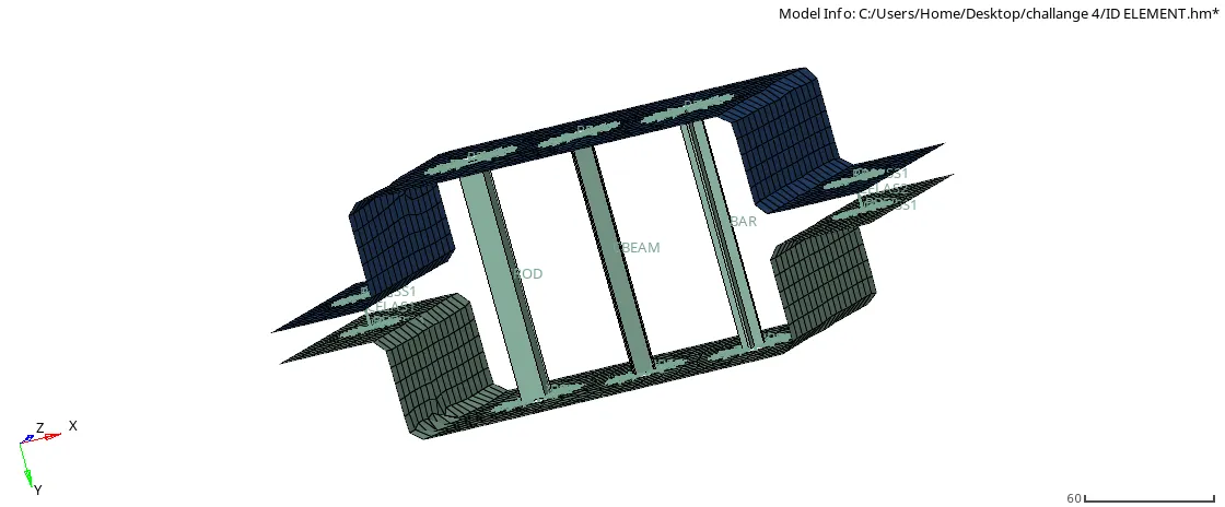
FINAL MESHED AND 1D ELEMENT ISOMETRIC VIEW