CONNECTION REPRESENTATION ON THE REAR DOOR OF THE CAR USING ANSA
AIM: The connection of the front door is shown in detail and the different types of connection techniques along with different 1D elements
PROCEDURE:
- IMPORT THE GIVEN MODEL
- CHOOSE THE SUITABLE CONNECTIONS
IMPORT THE GIVEN MODEL:
Import the given model from ANSA
FILE-INPUT-NASTRAN-CHOOSE FILE
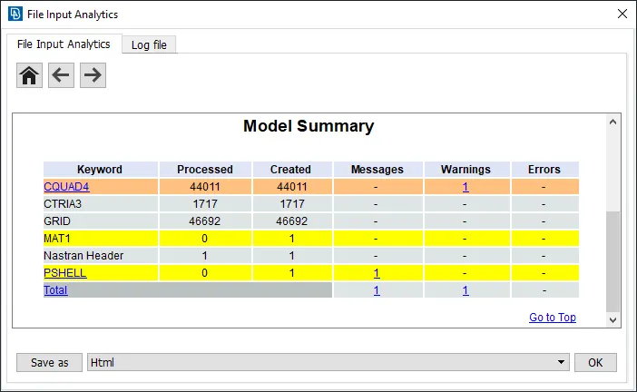
FIG 1 GIVEN MODEL DETATILS
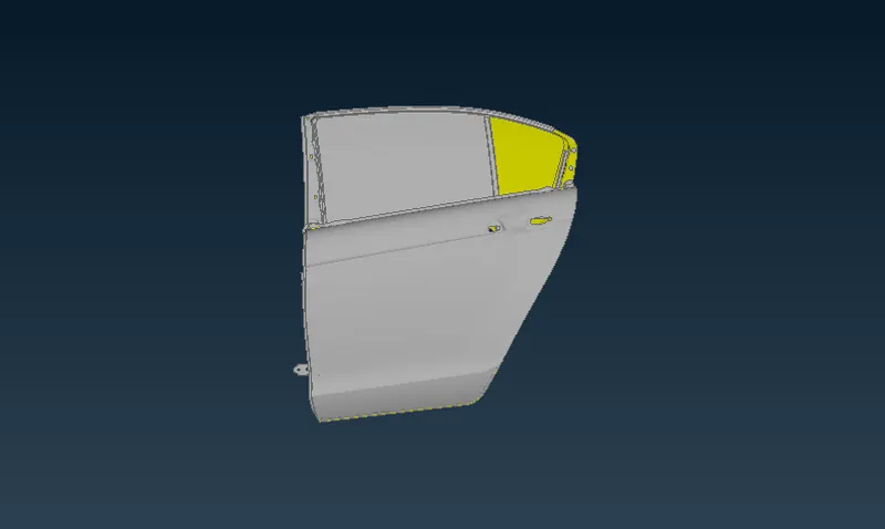
FIG 2 IMPORTED GEOMETRY
CHOOSING SUITABLE CONNECTIONS:
Bolt connection For Hinge:
for bolt connection, we need to represent the ON COG point, then convert the 3D point to bolt and the connect the bolt connection as shown below
COMMAND: SELECT ONCOG POINT- MIDDLE CLICK- SELECT P1&P2- FE TYPE
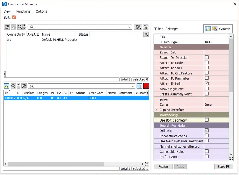
FIG 3 BOLT CONNECTION MANAGER
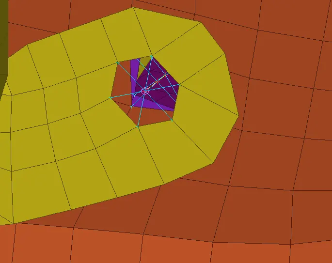
FIG 4 BOLT CONNECTION
TWO NODES RBE-2 CONNECTION:
The door is moving part of the vehicle body and to move them in the simulation process, the connection should also be adequeately.To have the correct connection to thr hinge part which connected in the hinge part, connected with the other part of the vehicle body, the z axis is rotations so we tends to remove the DOF. for z axis.
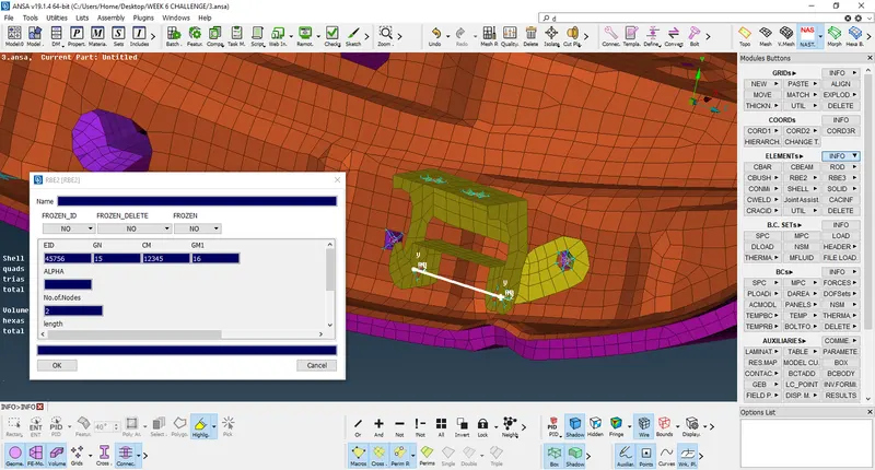
FIG 5 TWO NODED RBE2 CONNECTION
SPOT WELD CONNECTION:
for spot weld connection we need to create a ON COG point and then connect them as a spot weld
COMMAND:SELECT ON COG POINT- SELECT P1&P2- FE-(RBE3-HEXA-RBE3)
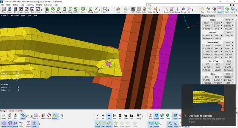
FIG 6 SPOT WELD CONNECTION
in some areas where the elements are not parallel to each other so we can use cluster RBE2 elements instead of spot weld, as shown in the below figure
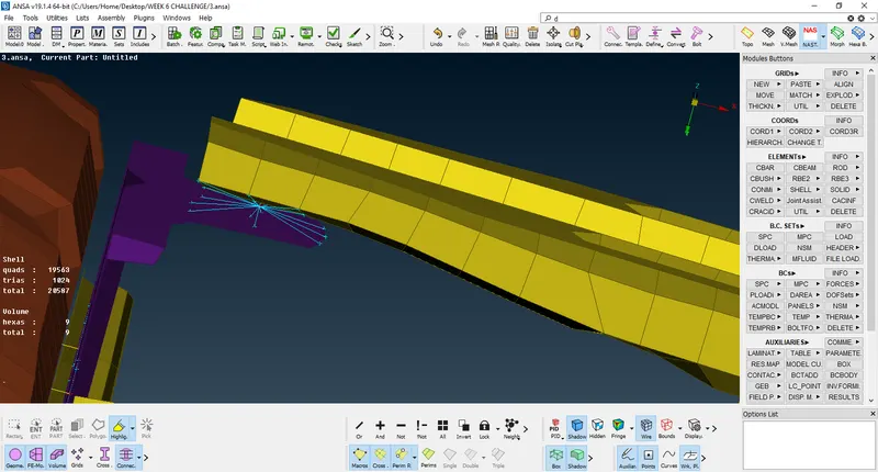
FIG 7 CLUSTER RBE2 CONNECTION
Some single holes are connected with the RBE2 connection:
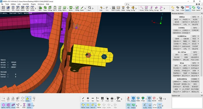
FIG 8 RBE2 CONNECTIONS
the above figure shows that the connection Representation of RBE2 elements.
HANDLE CONNECTION REPRESENTATION:
For the handle connection we need to connect with RBE2 connection and then connect with Two node RBE2 with suitable mass.
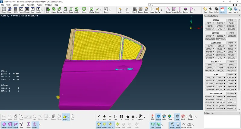
FIG 9 HANDLE CONNECTION WITH RBE2 (TWO NODE WITH MASS)
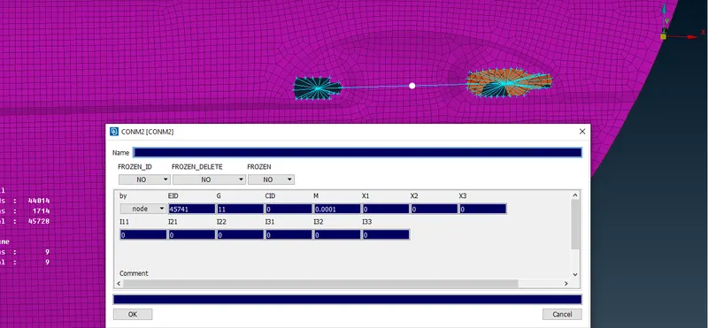
FIG 10 MASS GIVEN
for this handle connection we have given MASS as 0.001 tonnes, always make sure that the mass for every connection where needed should be given in tonnes alone.
BUSH CONNECTION FOR GLASS WINDOW:
before representing the bush connection we need to make a cure, for that
COMMAND:MESH-PERIMETERS-FEAT2CURVE-CHOOSE
the below image shows the cure represented.
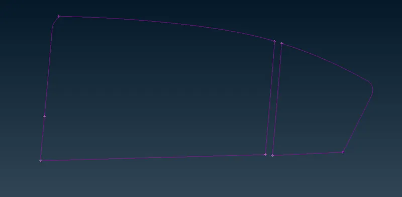
FIG 11 CURVES CREATION FOR BUSHES
after creating the curve we need to convert the curve as spot line and the set the new PBUSH PID
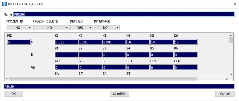
FIG 12 PBUSH PID
select the p1 and p2 and select the RBE3-CBUSH-RBE3 as shown in the below figure,
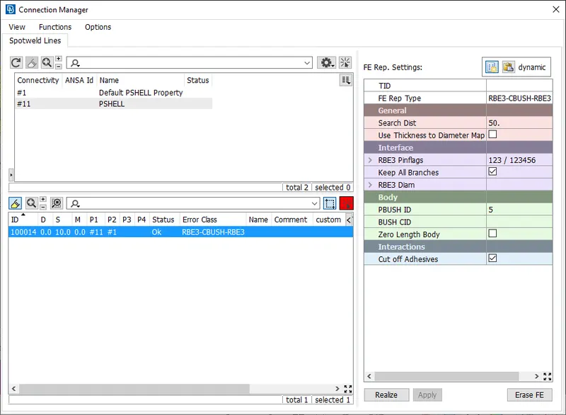
FIG 13 CONNECTION MANAGER FOR PBUSH CONNECTION
finally we get the PBUSH connection representaion here,
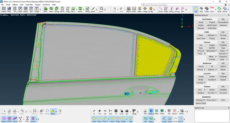
FIG 14 CONNECTION OF P BUSH
to allign the connection in the fine order we can do modify,
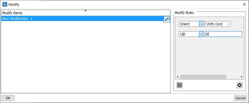
FIG 15 BUSH MODIFICATION
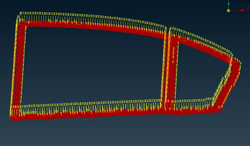
FIG 16 MODIFIED PBUSH
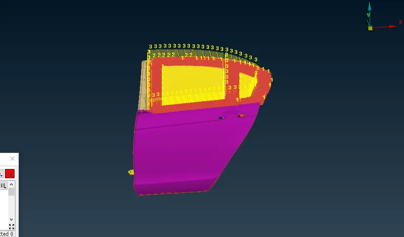
FIG 17 FINAL PBUSH REPRESENTATION
finally we got the BUSH CONNECTION REPRESENTATION
LEARNING OUTCOMES:
- In this we have learned different methods of connection representation as per requirements.
- we gained knowledge on where the connection are important for simulation purpose.
- learned how to deploy the connection like, bolt, seamweld, spot weld, bush etc..,
CONCLUSION:
- The Rear side Door of the car body has been connected with proper connection as per requirements and explained.
- The connection whuch are used, RBE2,RBE3,SPOTWELD,SEAMWELD,BOLT,&CBUSH.
- Finally The FE Connection done.
DRIVE LINK:
https://drive.google.com/file/d/1BAvcIgzp6xeicJIkzjnL4lg2UWJ5_0st/view?usp=sharing