PERFORMINF THE MESH ON THE PASSENGER VEHICLE SIDE DOOR PLASTIC TRIM USING HYPERMESH
PERFORMINF THE MESH ON THE PASSENGER VEHICLE SIDE DOOR PLASTIC TRIM
OBJECTIVE:
To Perform the Mesh on the passenger vehicle side door plastic trim using Hypermesh.
ABSTRACT:
Abstract: Vehicle interiors are primary source of injuries when occupants interact with them in the event of an accident. The extent of injuries is depending on energy dissipating characteristics of interiors and severity of accidents. For side impact tests vehicle interiors energy dissipating characteristics are assessed by FMVSS214 and ECE R95. Side impact test assesses occupant protection by door panel as vehicle interior during side intrusion test on door. In this paper, a certain type of car’s side impact performance is discussed. The purpose is to express the relationship of the side impact response during door trim intrusion and safety. First, A Finite Element Model (FEM) of door trim is established which is based on a logical method to solve the problem during the modeling process. Then, the analysis the evaluates the indexes of side impact safety, traces the designing, got the side impact feature and point test data of this type of car, and verified the practicability of simulation result in the door developing process. Finally, expresses the connection between the side impact response for door intrusion and safety of door, aiming at discussing the occupant safety during side impact. The
FE model is produced using Hypermesh 11 softwares and LS-Dyna solver is used for the simulations. The simulation results shows side impact protection system is capable of absorbing and dissipating required energy for protection of Pelvis.
INTRODUCTION:
In various traffic accidents, side impacts are frequent and often result in extremely harmful crashes. Global accident statistics show that side impacts account for approximately 30% of all impacts and 35% of total fatalities. Side impacts also require more attention because of considerably less crash zone for absorbing energy in the side of the cars compared to the front and rear structures anDconsequently the occupants sit almost within the crash zone, which often results in severe injuries. The region around the door of the vehicle is subject to large deflections into the driving personnel’s space during side impact, it is therefore necessary to produce a standard ‘worst case scenario’ design criteria that a design can be produced for and attempt to reduce the risk of injury to the occupants. On the road cars, however, much research has focused on the development of countermeasures including the vehicle side structure energy absorption and human response in side impact events. In period of development stage of the car, it is very important problems to the vehicle industry that the side impact crashworthiness is forecasted. Now days the normal practice is CAE modelling and analyzing the methods. Based on the analysis process of the subsystem design for side impact performance in the CAE developing process of a certain type car, the paper expounds on the problem solving principle and method for the car side impact FEM simulation.
PROCEDURE:
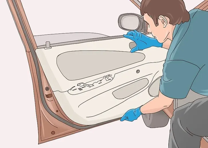
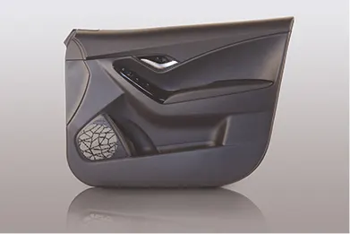
Here the aboove figure shows the inside side door plastic trim.
Meshing Quality Criteria:
Target Element Length = 4mm
| S.N | Quality Criteria | Value |
| 1 | Aspect Ratio | 5 |
| 2 | Skewness | 45 |
| 3 | Warping | 15 |
| 4 | Taper | 0.5 |
| 5 | Min. Length | 2mm |
| 6 | Max. Length | 6mm |
| 7 | Min angle Quad | 45 |
| 8 | Max angle Quad | 135 |
| 9 | Min angle Tria | 20 |
| 10 | Max angle Tria | 120 |
| 10 | Tria % | 10 |
Methods to do the meshing Process:
- First to import the CAD model.
- Delete the solids if any on the model.
- Generate the Mid surface extraction the model.(here the model is complex in geometry hence we choose manual midsurface for some areas.)
- Generate the mesh with given parameters.
- Assign the Material propereties with suitable thickness.
1.IMPORT THE MODEL:
After importing the model,checkl for solids and delete if any.
COMMAND: DELETE(F2)-SELECT SOLIDS-DISPLAYED-DELETE ENTITY
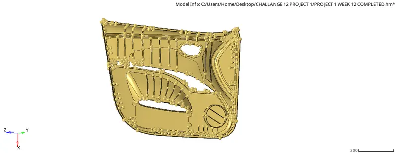
FIG1.1 IMPORTED MODEL
we need to check for geometry cleanup, to extract the Midsurface for the component.For cleanup the geo we can use toggle, and Defeature Options.
COMMAND:DEFEATURE-SURFACE FILLETS-ASSIGN MIN AND MAX RADIUS-FIND-REMOVE
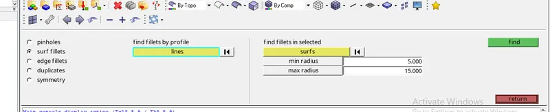
FIG1.2 TOOL BAR TO DEFEATURE
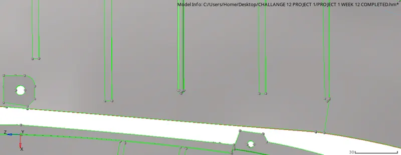
FIG1.3 DEFEATURE SURFACE
2.MIDSURFACE EXTRACTION:
For midsurface Extraction. we need to check the Geometry complexity.here the Model is more complex hence we can extract midsurface manually.
for manual midsurface:
COMMAND:GEO-SURFACE EDIT-OFFSET-SELECT SURFACE-DUPLICATE-OFFSET

FIG2.1 TOOL BAR TO OFFSET
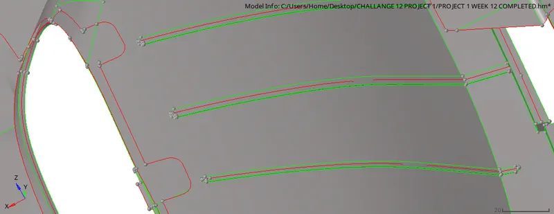
FIG2.2 MANUAL MIDSURFACE EXTRACTED
3.Extraction of midsurface using manual various techniques: Now the given plastic component is free from topological errors,now we can proceed to extract the midsurface using autoextraction method.
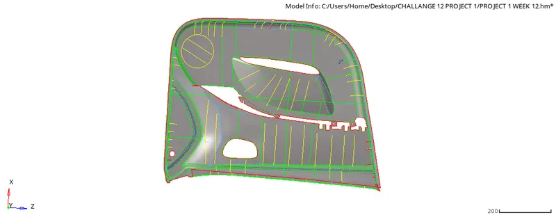
FIG3.1 MIDSURFACE EXTRACTED PARTIALLY AUTO
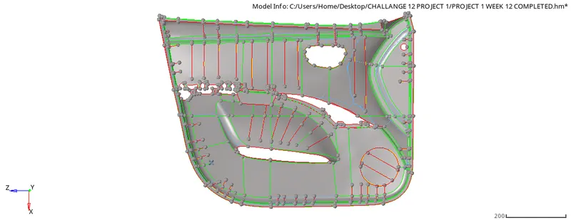
FIG3.1 MIDSURFACE EXTRACTED PARTIALLY AUTO
so in midsurface by auto extraction method there are some surfaces gets overlapped and some surfaces get disorted and missing due to complexity of the model so now we delete the midsurface and create a midsurface by manual techniques.Now we use a offset option to get a midsurface for the first we measure the thickness of each component,its a plastic component so thickness is varying in each part.first we offset a base surface which is 2.8mm thick.press shift+F9 or go to surface edit>offset>Continuous offset>select a surface>give offset value(half of 2.8)>choose vector direction>offset.For extract a midsurface of rib we also used offset option and for linear rib we also used another commandwhich is Midsurface>final edit tools>select both side of the surface>extract.
Now extend the rib to the base surface by using extend option which is in geo.>surface edit>extend>choose extend over edges>choose surf to extend is surf.to target.select the free edges line in line to extend over and select a surface over which line is extended in surf.to target then extend.
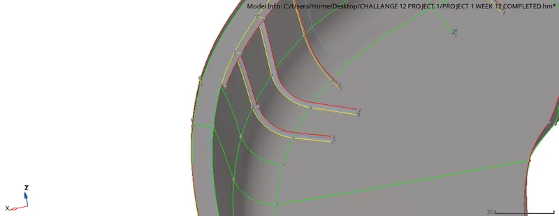
FIG3.3EXTENDING THE RIB TOWARDS THE SURFACE
4.Perform the 2D mesh on the midsurface: In order to mesh the midsurface first we input the given quality criteria and target element size as 4mm and element shape as mixed.
COMMAND: 2D-AUTOMESH-SELECT SURFACE-TARGET SIZE-MESH
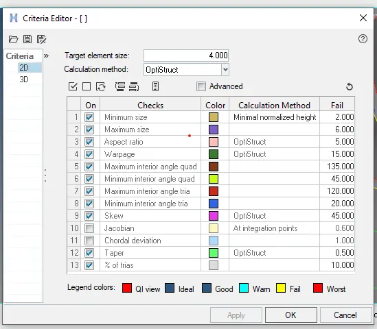
FIG4.1 QUALITY CRITERIA GIVEN
TERMS SHOULD NOT FOR QUALITY MESH:
No opposite trias on the model,
No back to back trias,
Avoid rotational quards.
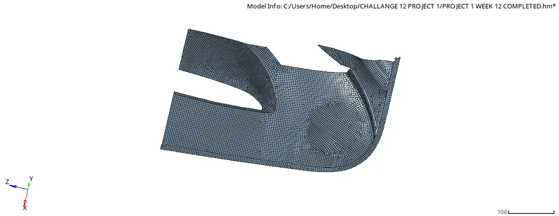
FIG4.2 MESHING SEPERATED PART 1
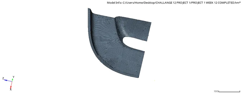
FIG4.3 MESHING SEPERATED PART 2
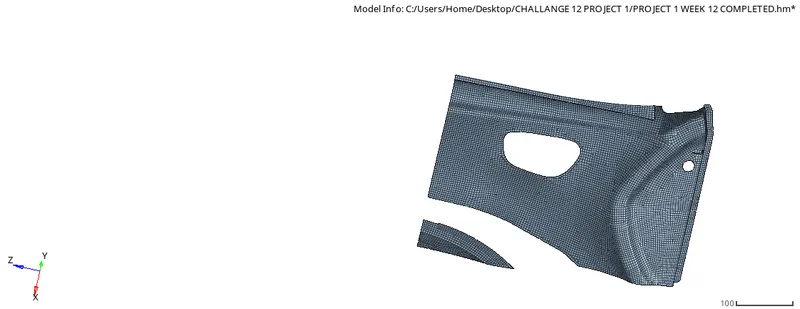
FIG4.4 MESHING SEPERATED PART 3
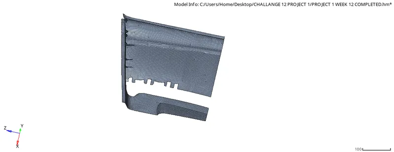
FIG4.5 MESHING SEPERATED PART 4
We mesh the complex surface in order to maintain the proper meshflow and make meshing easier while meshing the midsurface we make sure that we maintain the trias percentageas low as possible.while meshing curved or complex surface if the mesh doesnot properly catch the surface then we increase or decrease the node count so that mesh attaches the surface properly.
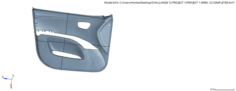
FIG4.6 MESH COMPLETED
5.Eliminate the failure element as per given quality criteria: After meshing the midsurface we check for element failure as per given quality criteria.this is performed in 2D>quality index>check element.we use various options like swap edge, drag element,split element etc in order to eliminate the error caused due to violation of quality criteia
we eliminate the rotating quads and tria present near the free or feature edges.we also reduce the trias concentration by dragging the trias to the free ends or combing the opp.trias by dragging near to each other.There may be a lot of quality errors which fails for wrpage,min,length,max.length,aspect etc.,so we rectify all the quality errors by using quality tools.Min or max.length error can be rectify by increasing or decreasing the distance between two nodes.For warpage we used translate option by shift +F4 and select the node give direction and magnitude , increase or decrease angle by translate option.
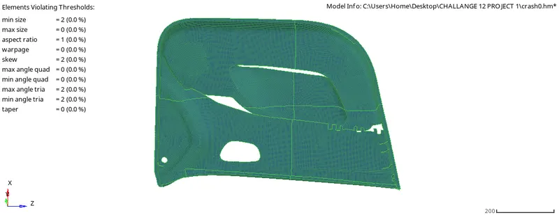
FIG5.1 MESHING QUALITY
6.ASSIGN THICKNESS FOR THE COMPONENTS:
After meshing copmpleted we can go with creating thickness for the components, before assigning the thickness we neec to create the material property for the components. After creating thr material and property card. we can organize the elements into suitable thicknes.
COMMAND: ORGANIZE-SELECT ELEMENTS-MOVE
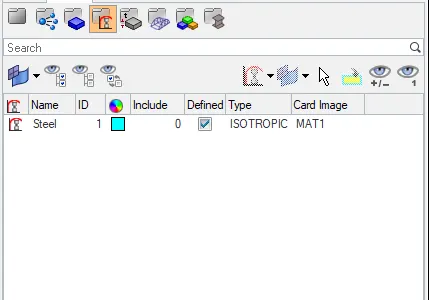
FIG6.1 MATERIAL CARD
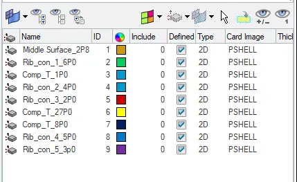
FIG6.2 PROPERTY CARD
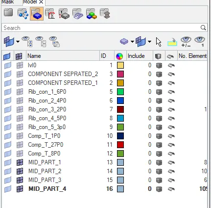
FIG6.3 COMPONENTS COLLECTORS
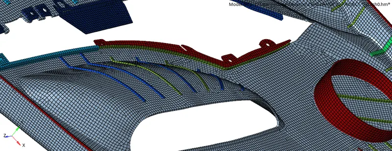
FIG6.4 2D DETAILED ELEMENT REPRESENTATION VIEW.1
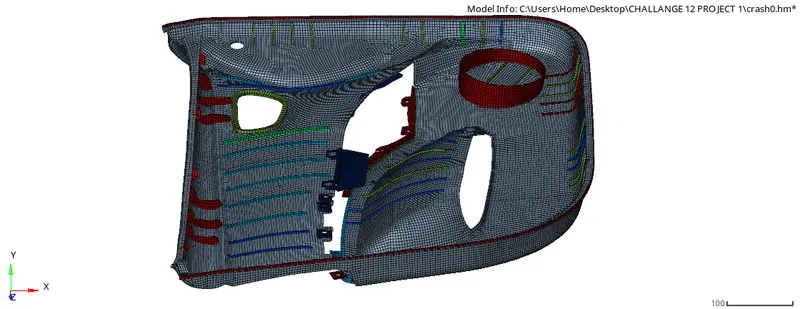
FIG6.4.1 2D DETAILED ELEMENT REPRESENTATION VIEW.2
7.CONCLUSION:
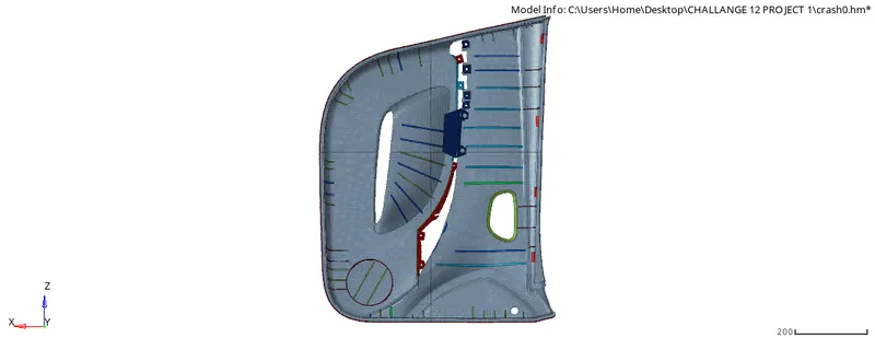
FIG7.1 FINAL MODEL.1
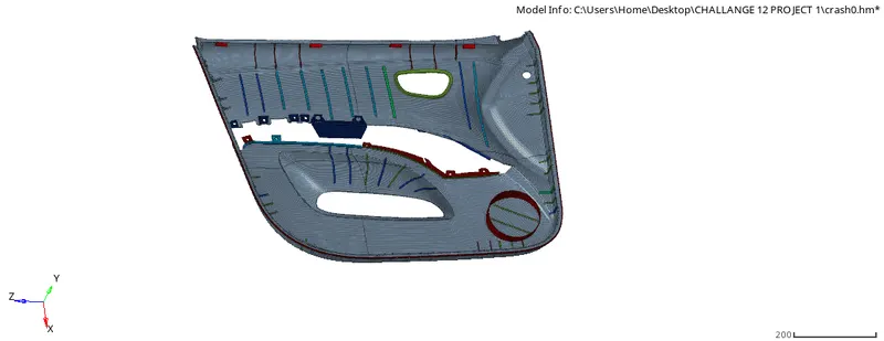
FIG7.1.1 FINAL MODEL.2
PROJECT OUTCOMES:
Learned meshing Automotive complex plastic part.
Knoweledge on creating midsurface on ribs and some complex areas.
knowledge on maintaining proper mesh flow.