MID SURFACE EXTRACTION AND MESHING FOR BACKDOOR MODEL USING HYPERMESH
MID SURFACE EXTRACTION AND MESHING FOR BACKDOOR MODEL USING HYPERMESH
NOTE: I HAVE ENCLOSED THE MODEL HERE BUT OUTER AND LOWER BODY MESH WAS ENCLOSED ONLY HALF PORTION DUE TO EXCEEDS OF NODE LIMIT. IF WE REFLECT IT WILL GET THE WHOLE MODEL.
Aim : To extract the mid-surface and the mesh the Backdoor model for a Hackbak car according to the quality criteria.
Abstract : The given component is a backdoor of a hatchback car.This part is a sheet metal and so the thickness is very low that is 0.75mm.So, instead of a 3D meshing we can go for 2D meshing and assign the thickness for thr 2D Shell mesh.
Procedure :
Step 1:Import the Geometry
This Model is a .igs format. So, i can import this model using import option and save into '.hm' file.
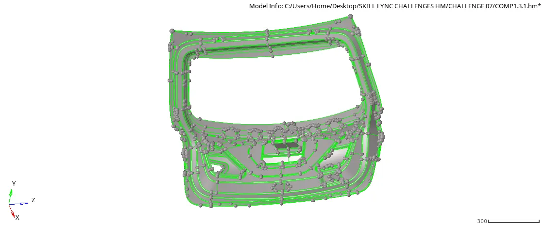
fig1.1 IMPORTED MODEL
Step 2: Geometry Cleanup
After this model is imported a lot of components are created and in geometry also have a single and tripple coons. So, First I can detach all the tripple coons and fix them into the proper surface.
After resolving all the ingle and tripple coons.Then I can organise the model namely,
a) Inner Panel
b) Outer Panel
c) Bottom
Step 3: Extracting The Mid-Surface
After Successfully organised the model, Remaining unwanted components I can delete and extracted the Mid-surface.Once, Mid-surface extracted I can Rename and Organized the model using the following component name.
a) Outer_Panel Mid_Surf
b) Inner_Panel Mid_Surf
c) Bottom
I am also tried Extracting Mid_Surf using Surface edit > Offset option.This Option is really helpful whenever the auto midsurface option is not extracted Mid_Surface well then we can extract manually using this option.
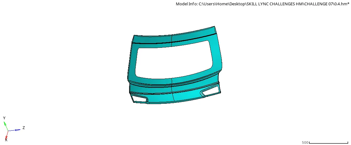
fig 1.2 OUTER PANEL UPPER BODY MIDSURFACE
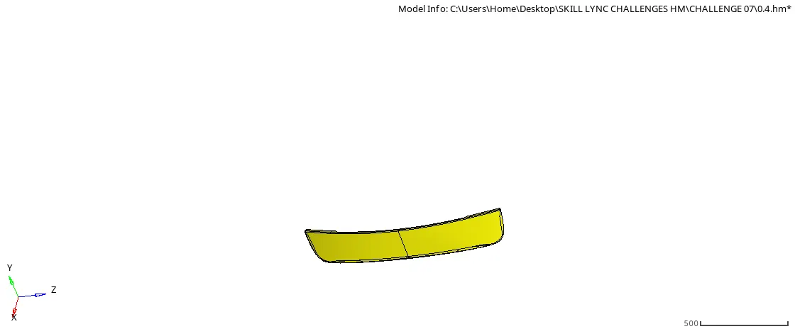
fig 1.2 OUTER PANEL LOWER BODY MIDSURFACE
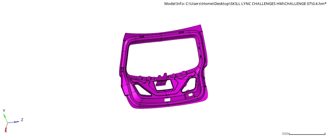
fig 1.4 INNER PANEL MIDSURFACE
Step 4: Symmetry check
Once the Midsurface is organised well. Next, I will jump out to the symmetry check.This model is totally symmetric. So I will only work half of the portion.Hence half portion is deleted.
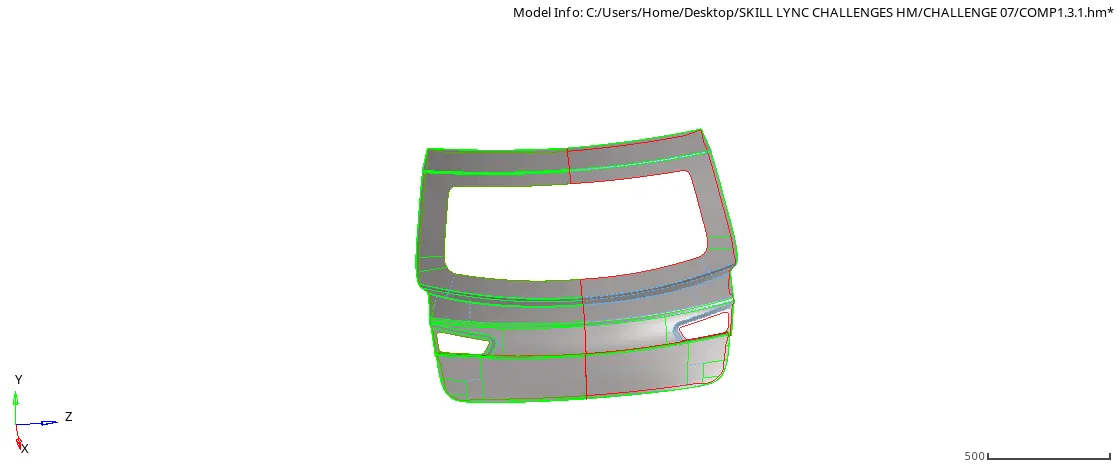
fig 1.5 SYMMETRY CHECK FOR MESH HALF PORTION
Step 5: Quality Criteria
The Next is to set up quality criteria as per given.
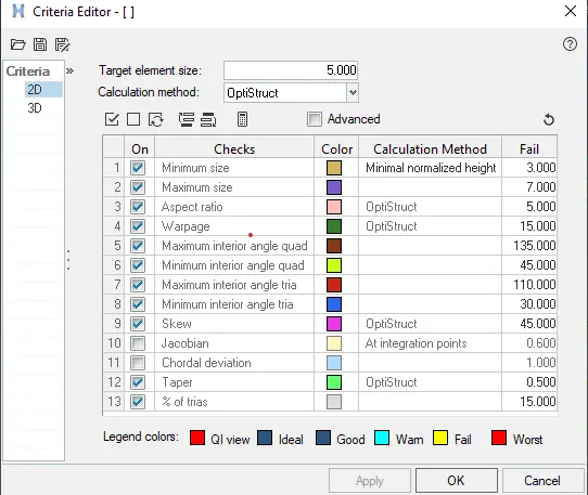
Step 6: Autocleanup
The autocleanup option is very helpful when the distance in two lines is less than the target element length.This option is toggled unwanted lines and connect the surfaces.
Step 7: Automesh
After Cleanup the geometry, Ican mesh this surface using the automesh option.
Step 8: Resolving Mesh
When the meshed this mode. A lot of trias are created.Usually, trias is not preffered for durability or any other simulation. So, I can convert all trias element into quad using Automesh>element option.
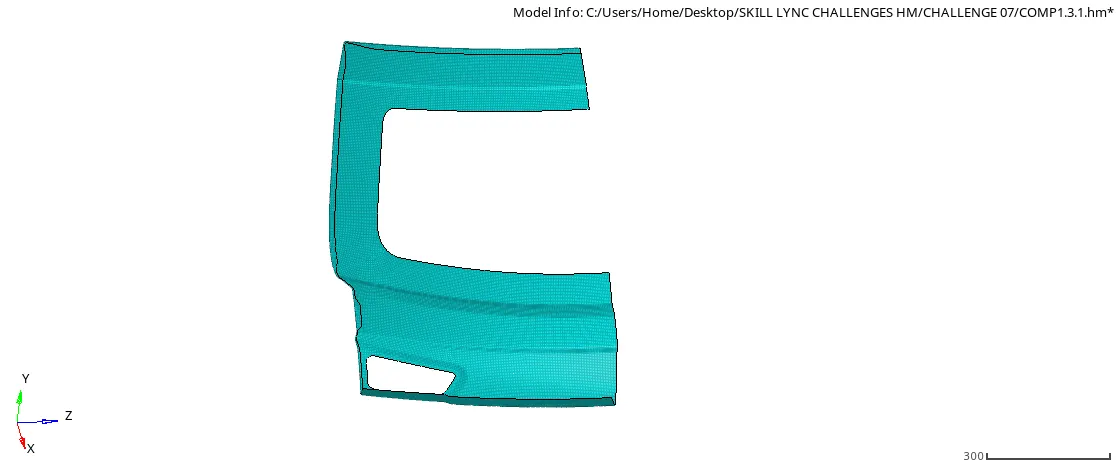
fig 1.6 UPPER BODY MESH HALF PORTION
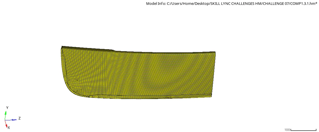
fig 1.7 LOWERBODY MESH HALF PORTION
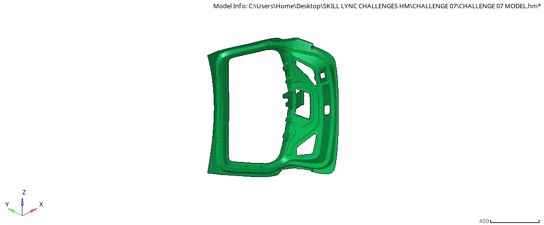
fig 1.8 INNER PANEL MESH PORTION
STEP 9: Reflect the Mesh
Once the mesh is fine as per quality criteria. I can reflect on the mesh using reflect option.
NOTE: DUE TO FINE MESH THE NODE ELEMENTS EXCEEDS THE LIMIT FOR STUDENT EDITION . SO ONE HALF OF THE SURFACE I UPDATED HERE BY REFLECTING THIS ON Z AXIS IT SHOWS THE
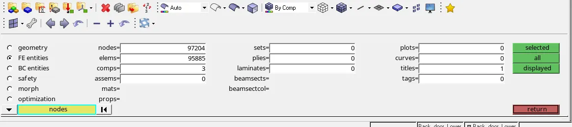
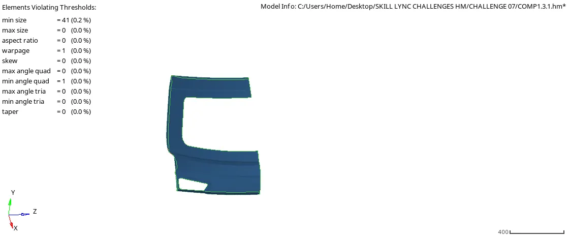
fig 1.9 QUALITY INDEX FOR UPPER BODY OUTER PANEL
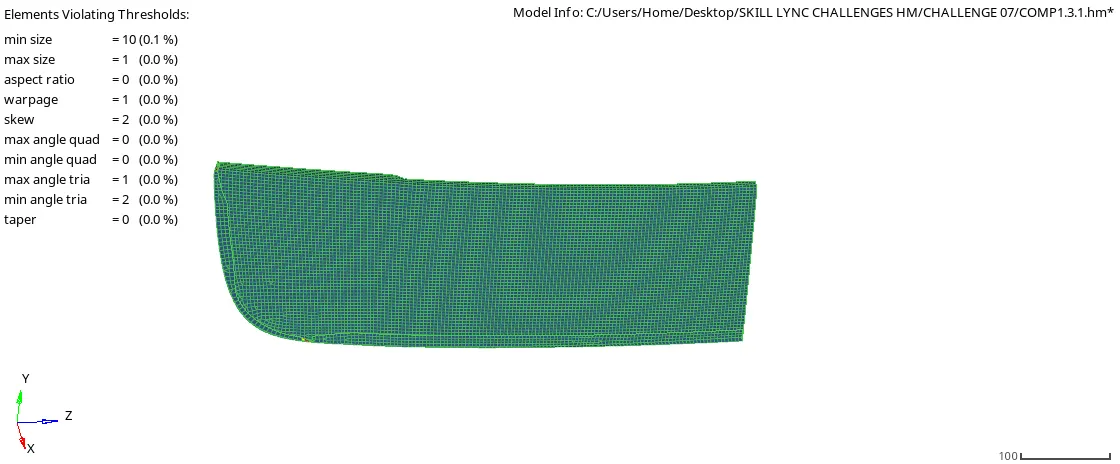
fig 1.10 QUALITY INDEX FOR LOWER BODY OUTER PANEL
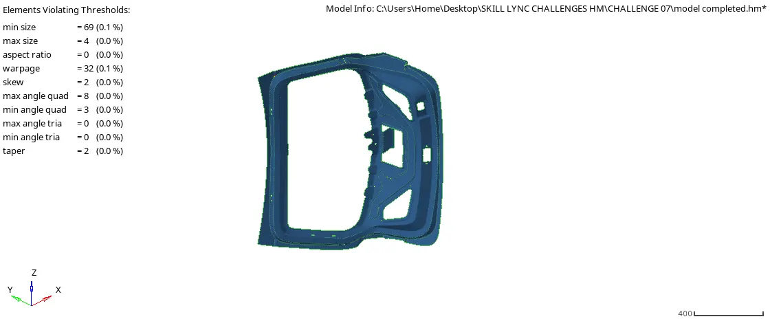
fig 1.11 QUALITY INDEX FOR INNER PANEL
Step 10: Check the Free Edges
After the reflect the mesh. The center mesh is not attached.So, I can use the Edges>Equivalence option to connect all the elements.
Conclusion:
After Performing the meshing for the backdoor model.I can able to understand how to mesh the geometry as per quality criteria and minimize the required meshing time.
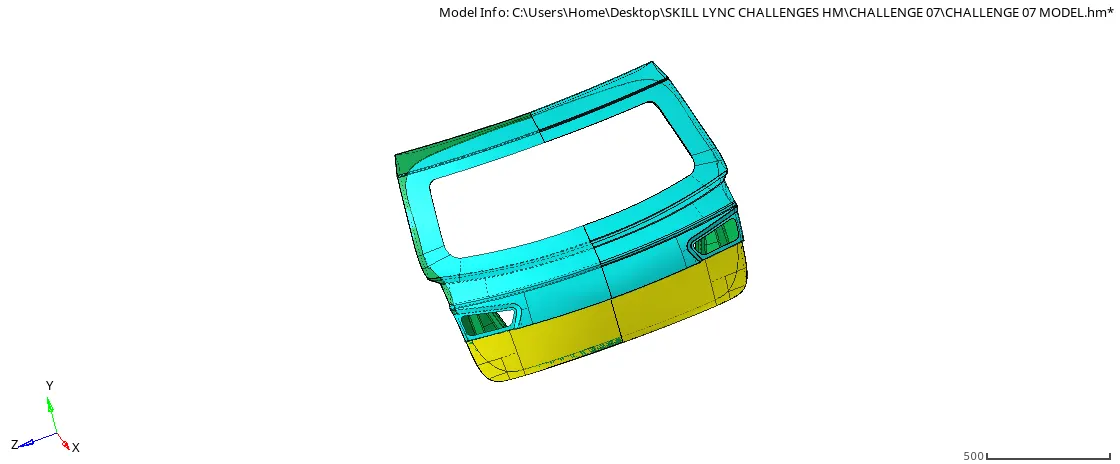
fig 1.11 FINAL MODEL
LEARNING OUTCOMES:
CREATING MANUAL MIDSURFACE
MESH WITH FINEMESH
REFLECT THE ELEMENTS AND SURFACES
REMESH THE FAILING ELEMENTS
REPLACING THE FREE EDGES