DIFFERENT METHODS OF 3D TETRA MESH ON HYPERMESH
DIFFERENT METHODS OF 3D TETRA MESHING
Objective :
Do the 3D mesh on the housing components,crank component and chassis assembly for the given element size,max and min length.
element size-5mm(for chassis and crank component use element size-6mm)
minimum length-2mm
maximum length-7mm
tet collapse-0.150
Procedure :
Housing Assesmbly:
In housing assesmbly,there are two components such as hub and cover.
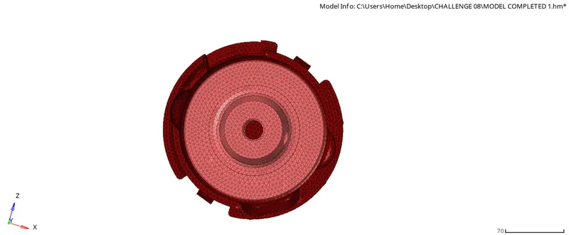
FIG 1.1 HOUSING ASSEMBLY
Hub:
In 3D mesh,there are four methods to do mesh.(first do 2D mesh and then use 2D shell elements to do 3D mesh,second directly do 3D mesh using volume tetra mesh, third do tetramesh using components which is enclosed component,fourth quick mesh in utility toolbar.
Now we can do two method,but we select for volume tetratool for that mesh also follows. First select 3D tool,then tetra mesh option and then select volume tetramesh(3D-Tetramesh-Volume tetramesh) Now give the element size 5mm for the target and give trias for the element type. Now the mesh was created.We have to check the mesh for that select mask tool and then select elements to mask now we would see the tetra elements inside the mesh. finally we have to check for the tet collapse,select check element-3D-tet collapse(0.150) Now we cannot see the failed elements to see that select saved filed in check elements tool and go to mask elements aand reverse.now we can see the elements failed.now cleanup the failed elements using distance tool manually. Finally check the quality and tet collapse will be in result 0%.
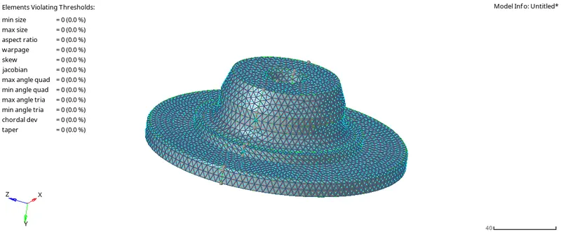
FIG 1.2 HUB 2D SHELL QUALITY
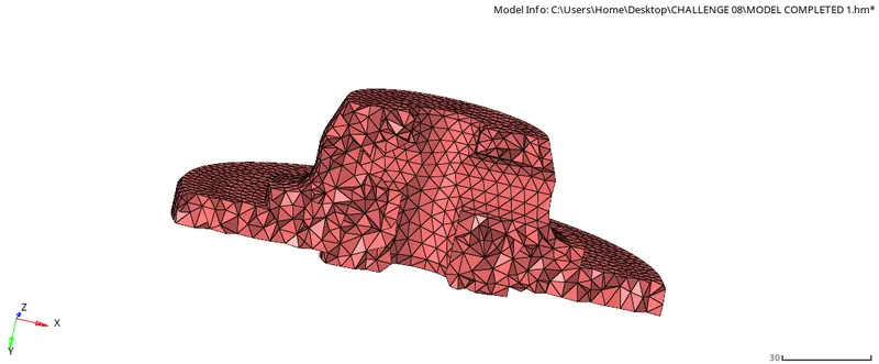
FIG 1.3 HUB 3D TETRA MESH
Cover:
Do the same process for the cover components as followed in hub component. Check the quality and tet collapse will be in 0% for that component.
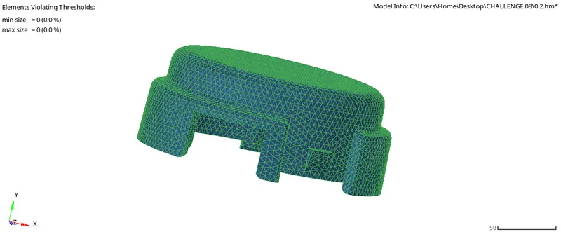
FIG 1.4 COVER 2D SHELL QUALITY
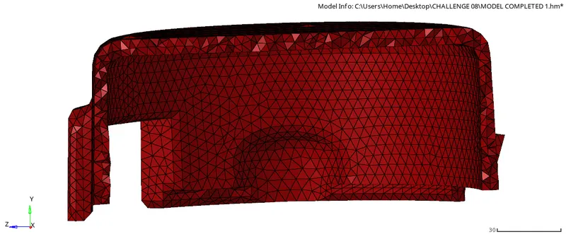
FIG 1.5 COVER 3D TETRA MESH
MODEL 2:
Crank component:
Select the component and we can go with quick tetra mesh because we don't have solid surface to do volume tetra.
Select VIEW-BROWSER--HYPERMESH-UTILITY-GEO MESH- SELECT COMPNENT- MESH.
here, we can give our given size min-2mm element size-6mm then go with mesh.
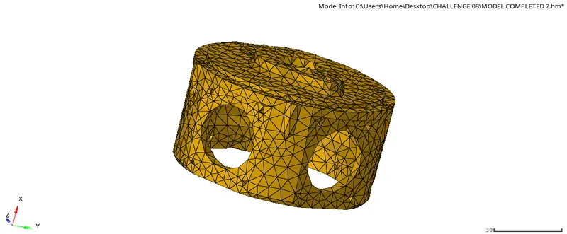
FIG 2.1 CRANK 3D QUICK TETRA MESH
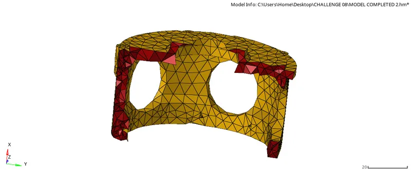
FIG 2.1.1 CRANK 3D QUICK TETRA MESH
MODEL 3:
CHASIS ASSEMBLY:
COMPONENT 1: Import the model and do the geometry clean using topo mode option.
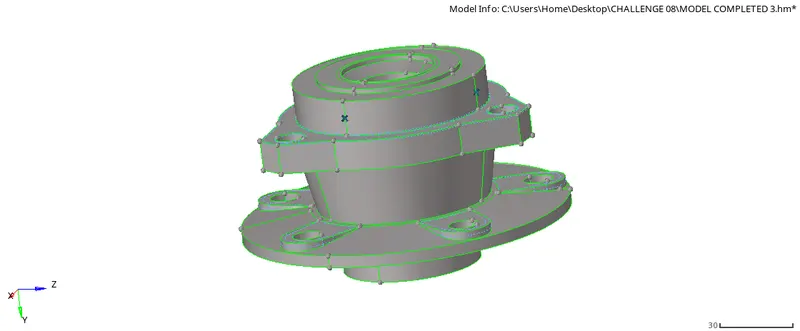
FIG 3.1 GEO CLEANUP OF COMPONENT
Do 2D mesh for the given component and go for 3D tetra mesh. with the element size 6mm
After 2D mesh check for quality and clean up using remesh.
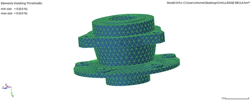
FIG 3.2 2D MESH QUALITY
After clean up the elements failing on 2d mesh go with 3D tetra mesh. select the 2d shell elements and select 3D mesh.
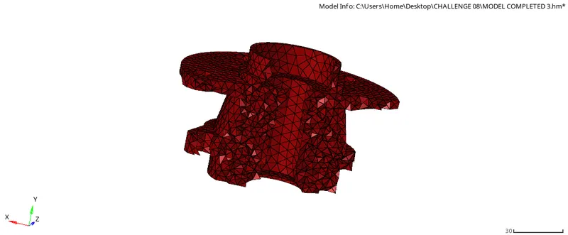
FIG 3.3 2D SHELL TO 3D TETRA MESH
COMPONENT 2: Now select the second component and we can go with quick tetra mesh because we don't have solid surface to do volume tetra.
Select VIEW-BROWSER--HYPERMESH-UTILITY-GEO MESH- SELECT COMPNENT- MESH.
here, we can give our given size min-2mm element size-6mm then go with mesh.
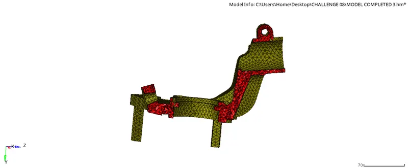
FIG 3.4 3D QUICK TETRA MESH
after completing mesh check for tet collapse and remesh it also do measure and re arrange the tet collapse distance, while doing re mesh we can give also tetra mesh parameters also.
COMPONENT 3: Now select the THIRD component and we can go with quick tetra mesh because we don't have solid surface to do volume tetra.
Select VIEW-BROWSER--HYPERMESH-UTILITY-GEO MESH- SELECT COMPNENT- MESH.
here, we can give our given size min-2mm element size-6mm then go with mesh.
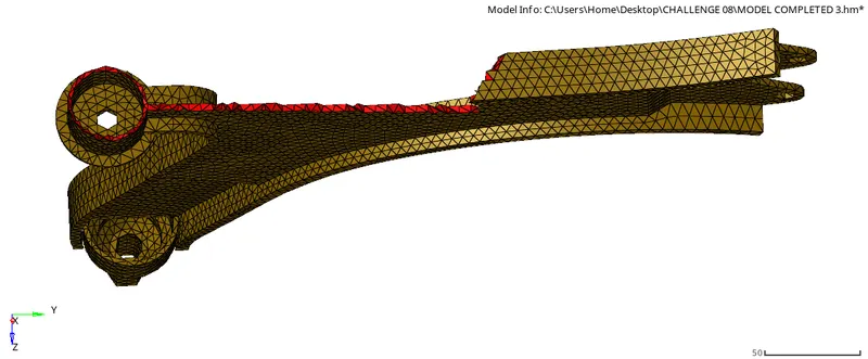
FIG 3.5 3D QUICK TETRA MESH
after completing mesh check for tet collapse and remesh it also do measure and re arrange the tet collapse distance, while doing re mesh we can give also tetra mesh parameters also.
COMPONENT 4: Now select the FOUR component and we can go with quick tetra mesh because we don't have solid surface to do volume tetra.
Select VIEW-BROWSER--HYPERMESH-UTILITY-GEO MESH- SELECT COMPNENT- MESH.
here, we can give our given size min-2mm element size-6mm then go with mesh.
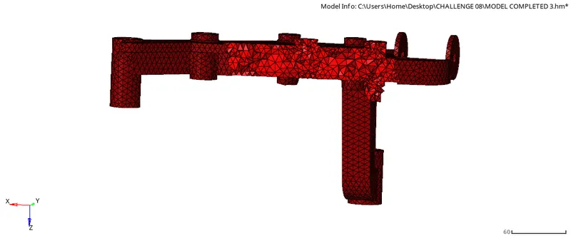
FIG 3.6 3D QUICK TETRA MESH
After completing mesh check for tet collapse and remesh it also do measure and re arrange the tet collapse distance, while doing re mesh we can give also tetra mesh parameters also
FINAL MESH:
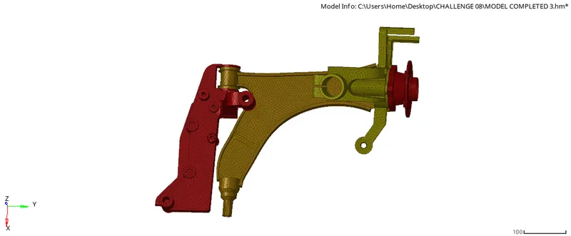
FIG 3.7 FINAL MESH
CONCLUSION:
MODEL 1 - USING 2D SHELL ELEMENT MESH TO 3D TETRA MESH.
MODEL 2- QUICK TETRA MESH.
MODEL 3- COMPONENT 1- USING 2D SHELL ELEMENT MESH TO 3D TETRA MESH.
COMPONENT 2,3&4 - USING QUICK TETRA MESH.