Project 2
Statement of assignment:
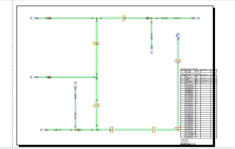
Route the Wiring harness on the Given car body and Prepare to to flatten the view drawing in CATIA V5. Application of all Packaging rules, Industry best practices studied in this course shall be demonstrated in design. Apply Protection coverings as required.
Available connector 3D data can be used, or you can download the connectors from www.te.com
Prepare & Submit all necessary reports like clearance, Clipping/Clamping selection, Harness fixing requirements, Harness continuity, and Assumptions if any along with CATIA 3D data.
Introduction-
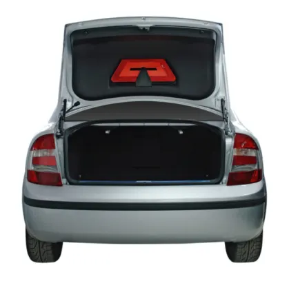
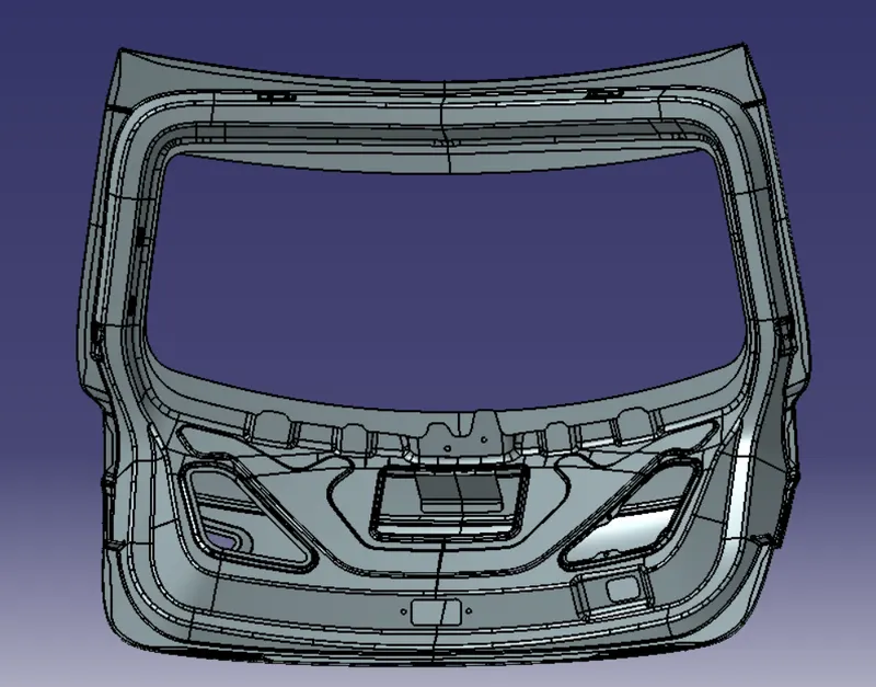
The trunk or boot of a car is the vehicle's main storage or cargo compartment it also have a hatch at the rear of the vehicle. It is also called a tailgate.These doors can be operated manually or electric powered. here we design the trunk or back door wire harness using the Catia.The Backdoor is an assembly of many parts such as inner panel, outer panel upper, outer panel lower and Reinforcement.Inner panel is attached to the outer panel using mastic sealant.
Rules :
1. routing should be done in a manner that it can be easily manipulated
2. Easy maintainability, installation, manufacturability, etc should be taken into consideration.
3. The branch length should be greater than 50mm.
4. The minimum distance between the clip and branch point should be at least 25mm
5. The minimum distance between the two branch points should be at least 50mm.
6.Clips/clamps used for the wiring harness should be easily available in the market to avoid extra cost for custom mounting solutions
7 Avoid routing through blind spots and hard to accessible places.
Back door assembly: The back door assembly has multiple connections for a tail lamp , indicators , number plate lamp and wiper mechanism. The inter connection is placed near to the opening and closing mechanism which is above hinge.
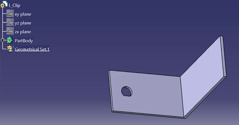
An L clamp is taken to mount the interconnector to the backdoor
Connectors has to be electrically defined . we take 2 major connectors one for interconnection and other for all component connections.
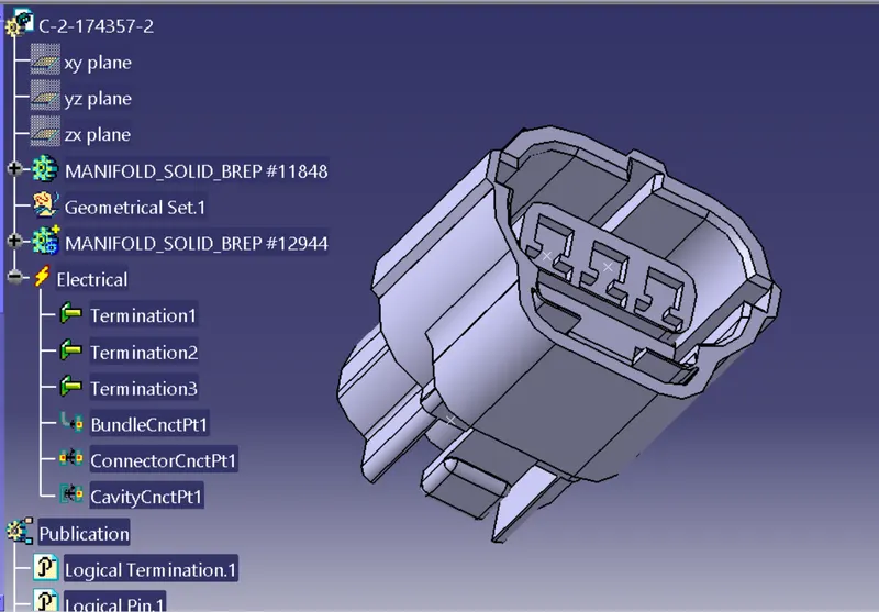
For interconnector we take C-2-174357-2 . The connector is mechanically and electrically defined to mount and connect the bundles.
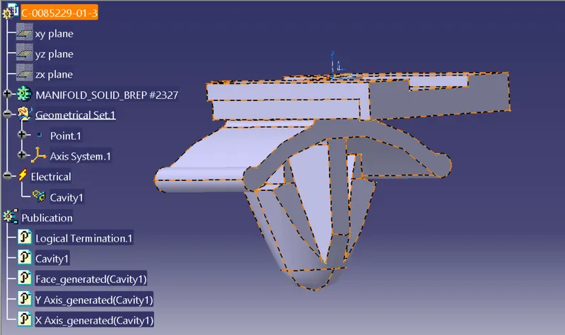
A mounting clip is used to mount the above connector to the L clamp.
The mounting clip is electrically defined and connected to the connector through a clamp by means of electrical connection.
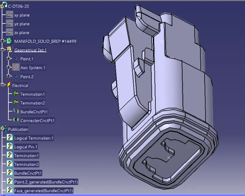
The Second connecter we choose is a C-DT06-2S for all other 7 connectors to the components .These are electrically defined.
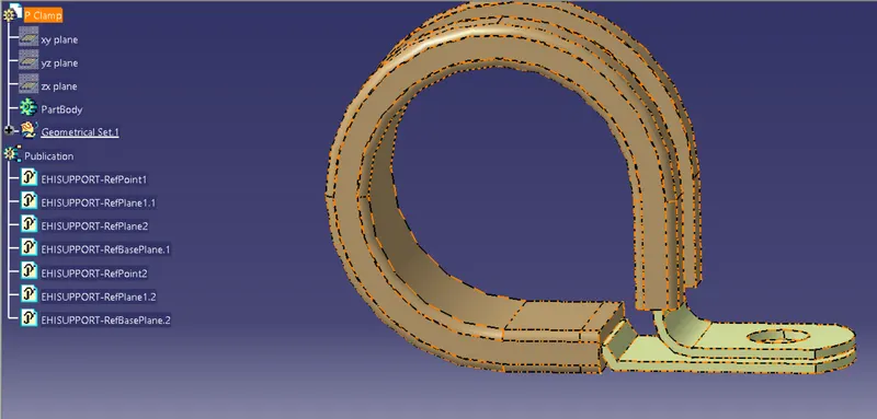
We select 3 supporting elements inorder support the wiring throughout the routing . These are P clamp , U clamp , Furr tree clip. These are all defined as an supporting part in catia v5.
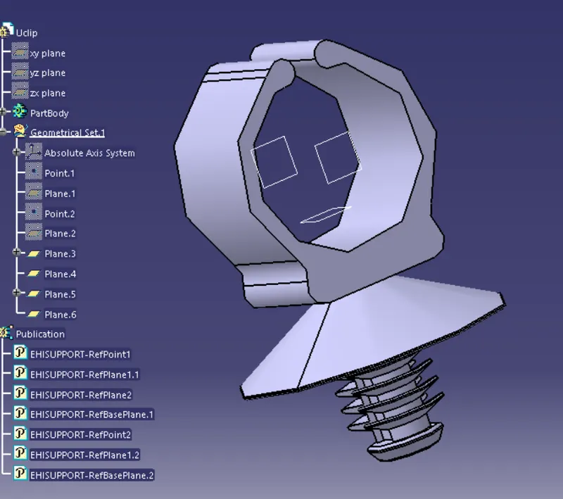
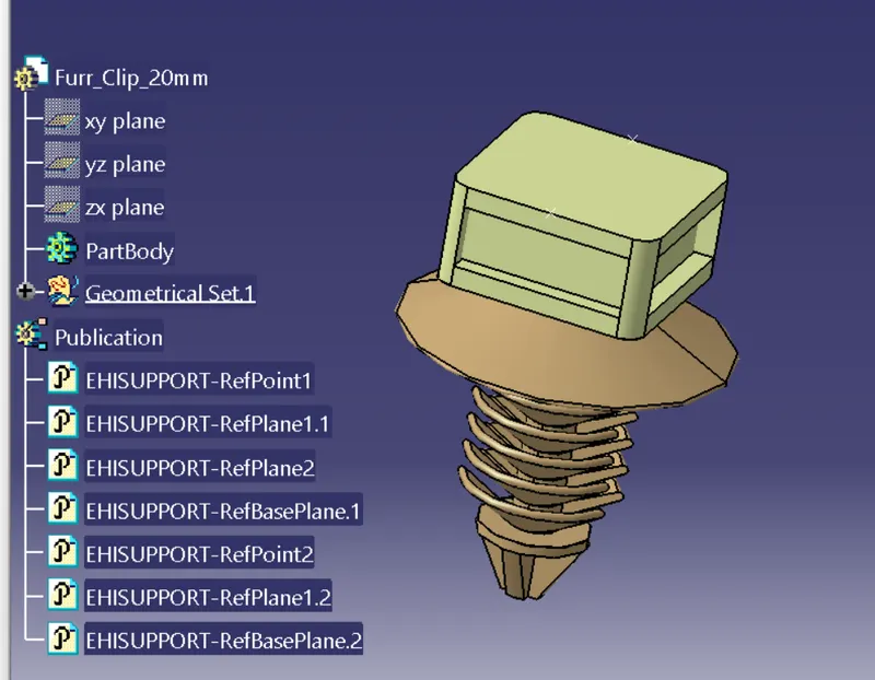
Now the connectors and supporting parts are placed in the right places with the help of assembly workbench move tools as shown below.
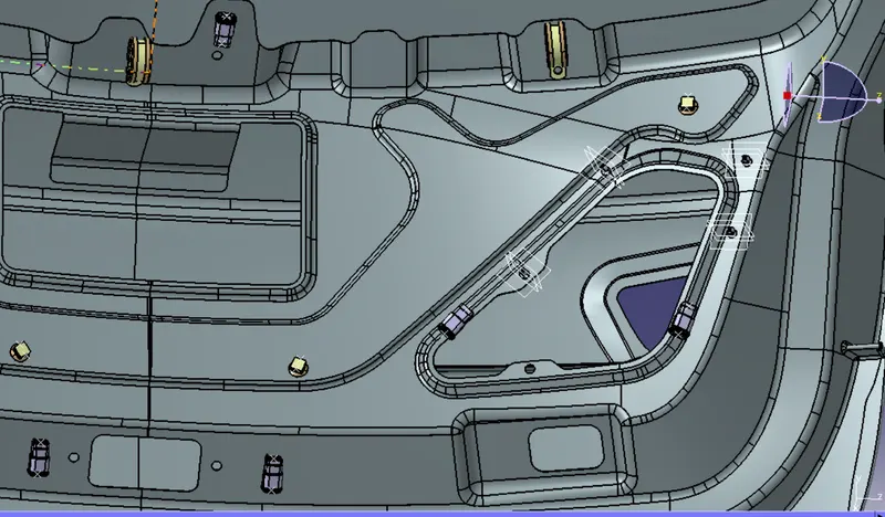
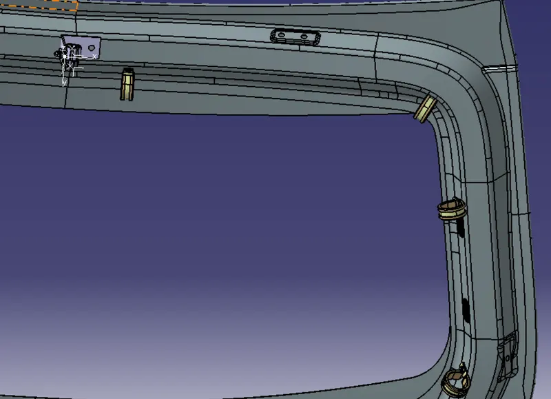
Once the components are in place we start the routing from the interconnector.
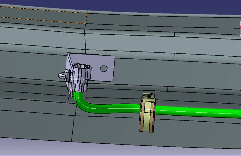
Now we continue the connection through the whole p clamps and further connect the components.
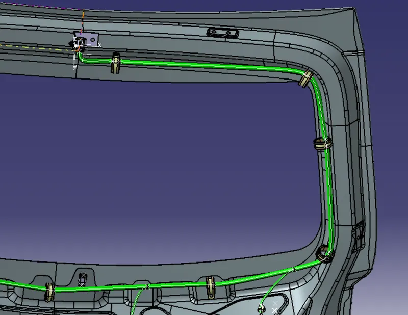
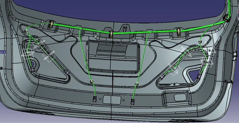
Once the routing is done we check for the continuity from the edit search the electrical bundle segment is fully connected.
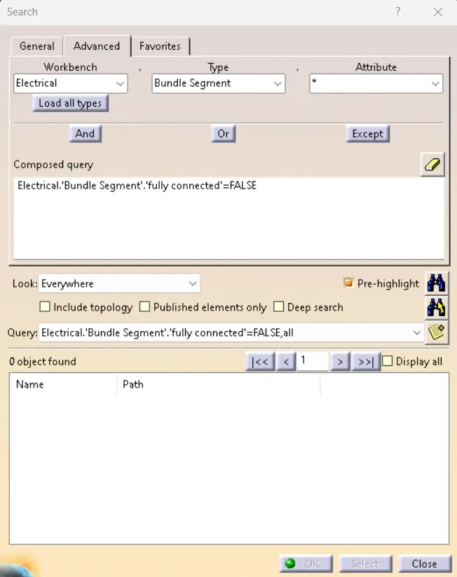
Once it is done we install the cot tubes as shown below.
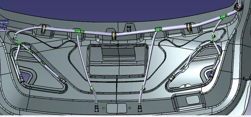
Once the routing is checked for fully connection, Create a new product and set the flattening parameters .
Now extract the bundle and straighten the wire diagram,
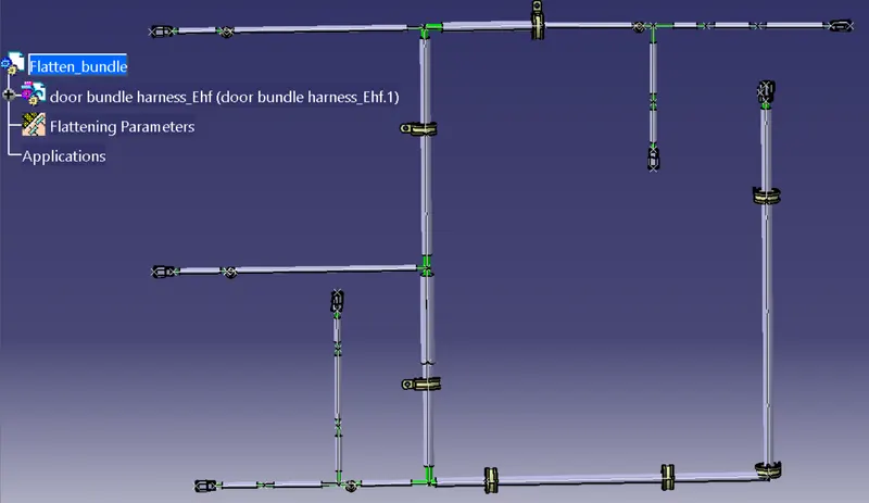
This straightened bundle is further taken into consideration for drawing and for which a new drawing page is created.