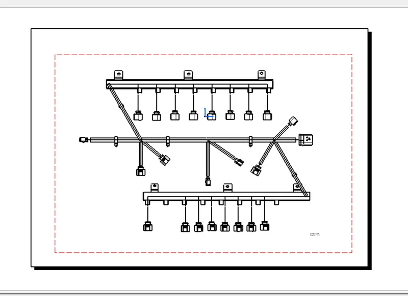
Project 1
Statement of assignment:
Route the Wiring harness on Given Engine and Prepare flatten view drawing in CATIA V5. Application of all Packaging rules, Industry best practices studied in this course shall be demonstrated in design. Apply Protection coverings as required.
Available connector 3D data can be used, or you can download the connectors from www.te.com
Prepare & Submit all necessary reports like clearance, Clipping/Clamping selection, Harness fixing requirements, Harness continuity, Assumptions if any along with CATIA 3D data.
First of all load the engine part data to the CATIA environment and name it as engine part assembly.
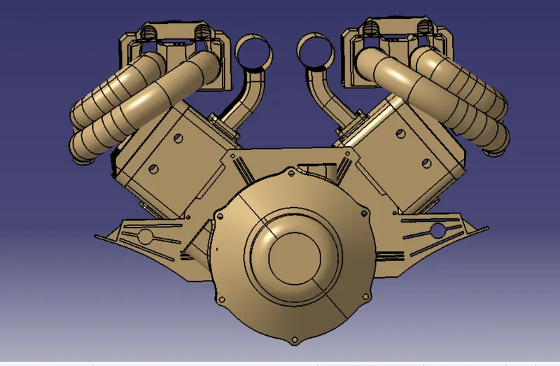
Now create a product file and name it the engine harness context and include this engine drawing to the tree.
Now inside the engine harness context, create a harness bundle file for electrical components and bundle routing.
Each component from the part file has to be opened separately in order to define electrically with help of mechanical and electrical part design workbench.
C-1563689 is the main connector used in here it is defined mechanically for point allocation and electrically for bundle entry .Now the
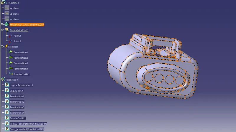
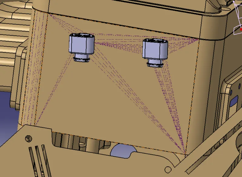
Now, to define a connector electrically we should define the geometrical parameters like bundle connection point and connector connection point in the Electrical Part Design workbench for the downloaded connector. we are placing connectors to fuel injector sensors and cam-shaft sensors. So we will require a total of 20 connectors which have to be added to the Engine Harness Geometrical Bundle Assembly. We have to use manipulation tools along with a compass, snap and smart move features to locate all the 20 connectors at their desired locations
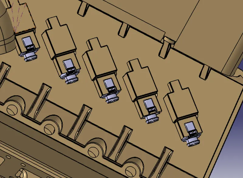
a 12 pole connector "C-776438-4" and mounting cavity "C-1924487-2" is together used as interconnection connector. The data is downloaded from TE website and these are now electrically defined.
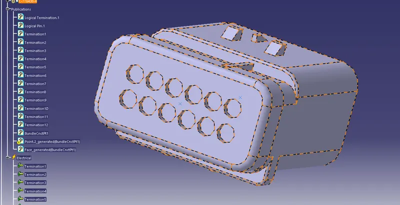
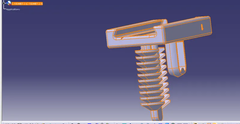
Both are defined for the mounting provision and the connector is defined for bundle entry and connector connections.
Now we use an L clamp to connect these to the engines shawn below.
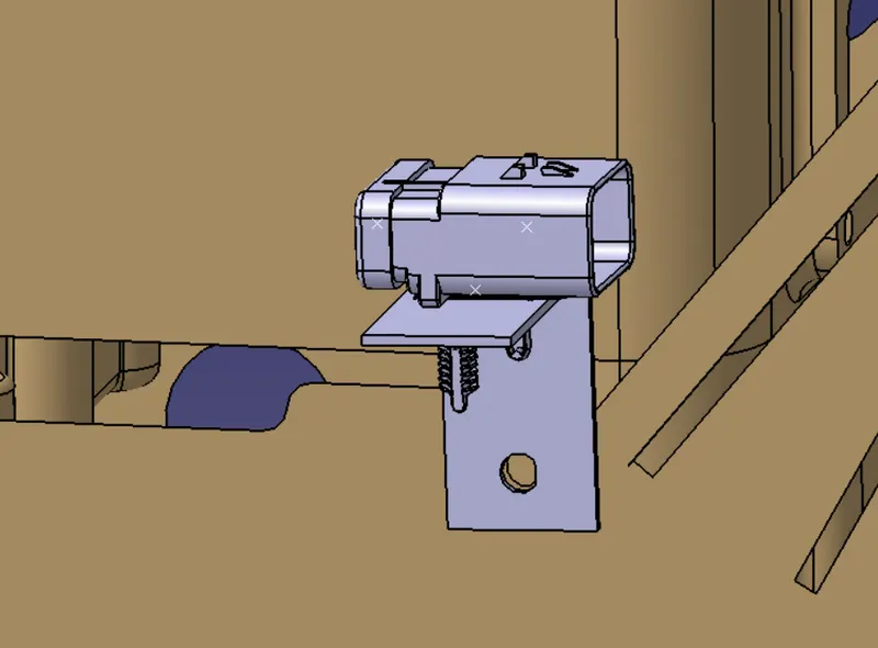
Pclamp is used to support the bundle to get it to the desired location without damaging or overhanging the bundle.
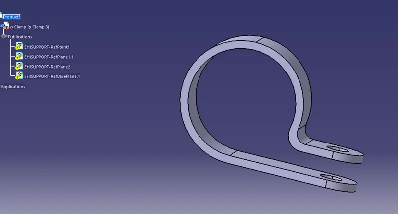
These are defined electrically for wire entry and exit.
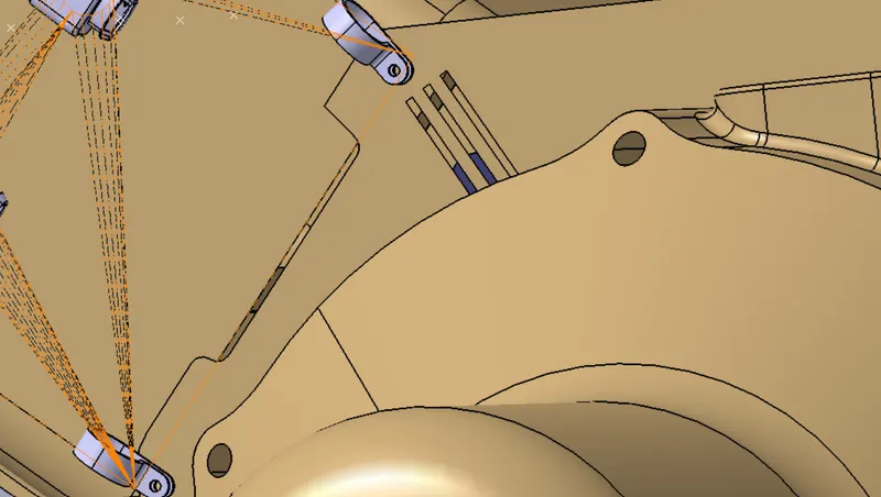
The furr clips are also used to support the wires which has to be electrically defined for entry and exit.
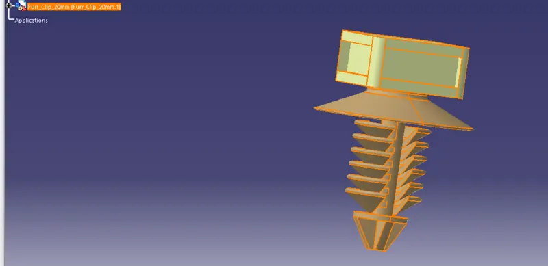
Fur tree clips are fixed using manipulation and snap tools.
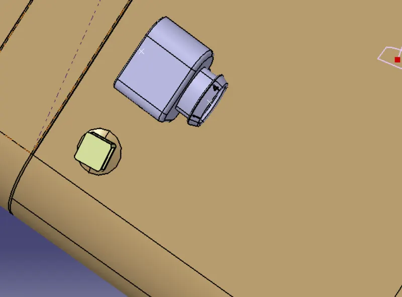
We have to add now plastic guiding channel because Bugatti V16 engine has 8 injectors on right side and 8 injectors on left side which are very close to each other. Hence plastic guiding channel is best option for proper and easy routing of the wiring harness. It will reduce the complex wiring harness routing.
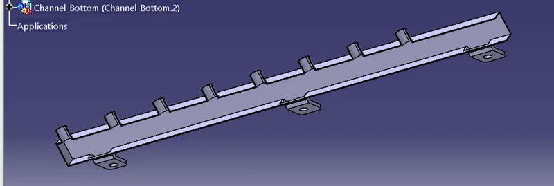
This channel has to be electrically defined in the main entry and 8 different exits. The above figure shows the left-side guiding channel and the same process will be repeated for the right-side channel.
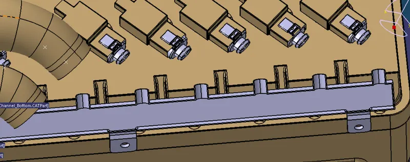
After electrically defining of guiding channel, we have located the guiding channel at a desired place as shown in the above figure. Here, we have used different commands like manipulation, snap, smart move, compass, etc. for placing of guiding channel.
Now that al the component parts are brought to the desired location, now we can start routing the bundle. Which we switch the workbench to the harness assembly and the routing is started from the interconnector as shown below.
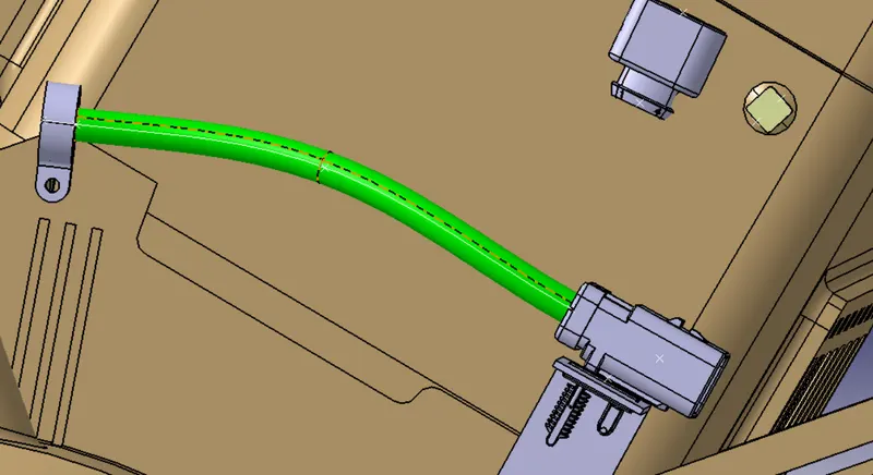
and we produce a branch for the connector connections and to route to the fur tree clip.
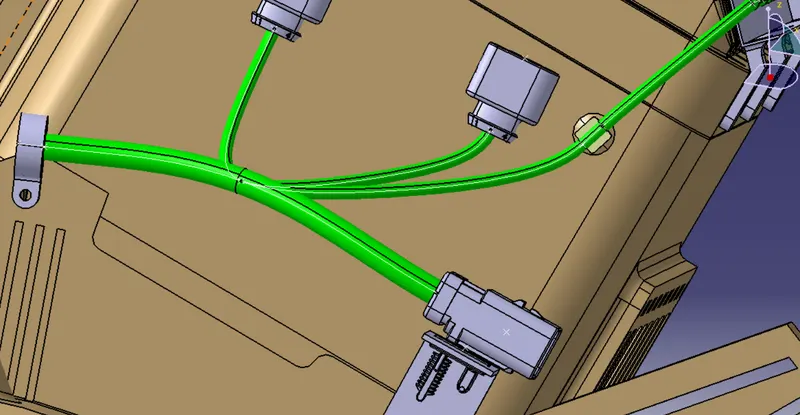
These are further connected as shown in the figure above.
Once the normal connections are made the channel connections re done and complete the routing as shown below.
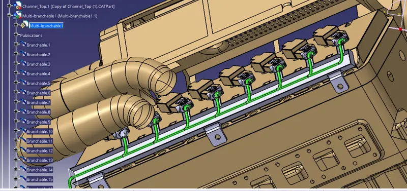
Now its time to add the protection covering using the cott tubes.

The cott tubes are given one by one so that we can fix the end and start the extremity accordingly.
Now its time to check the continuity of the bundle we use the search option in which the advanced tool has an electrical bundle segment - fully connected. we check for false command and make sure every single connection are made properly.
Creating flattened view of the engine harness geometrical bundle assembly
In this step, for creating a flattened view we have to work on the Electrical Harness Flattening workbench of Catia V5. We should also make sure that the flattening file is saved in the same folder where other files of harness assembly are saved.
Once it is done we need to extract from the active plane to the flattening bench and use the rotation and straightening tools to arrange the connection to something like the fig given below
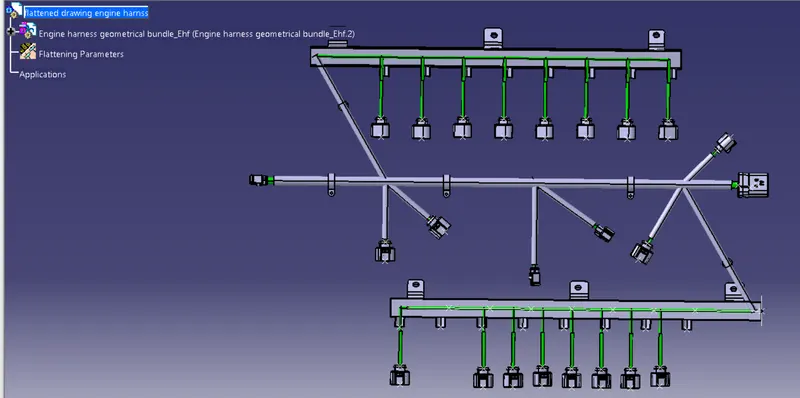
Once we get the flattened file now it's time to create the drawing file. we are creating a new drawing file and defining all the necessary drawing parameters. We have to insert the front view of the Engine Harness Flattening Product file into the Drawing file