Project 1 Mechanical design of battery pack
Project 1 Mechanical design of battery pack
Battery pack capacity: 18 kWh
Cell: ANR26650M1-B
AIM :
Prepare a detailed battery pack drawing along with its enclosure. State your assumptions.
STUDY :
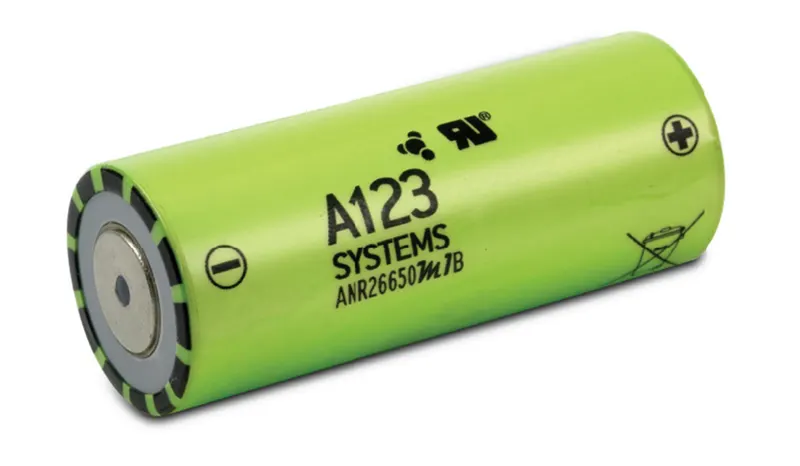
The ANR26650M1-B is the next generation of A123 Systems’ pioneering 26650 cylindrical cells, now with greater power and energy density and lower impedance. This versatile lithium-ion cell is suitable for a wide variety of applications and system designs. Proven performance in the most challenging conditions, combining durability, reliability, and safety, the ANR26650 cell offers an excellent combination of price performance.
Cylindrical Cell Primary Applications
- Portable high-power devices
- Stationary battery backup systems
- Grid stabilization energy storage systems
- Commercial truck and bus hybrid electric vehicles (HEVs)
Nanophosphate® LiFePO4 Benefits
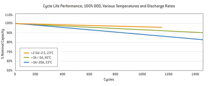
- Cycle Life at 1C/1C, 100% DOD, > 4000 cycles
- Safety: Excellent abuse tolerance and environmentally friendly
- Life: Excellent calendar life, 10X cycle life vs. conventional lithium-ion
COMMERCIAL SOLUTIONS
Advanced lead-acid replacement batteries for:
- Datacenter UPS
- Telecom backup
- IT backup
- Autonomously guided vehicles (AGVs)
- Industrial robotics and material handling equipment
GOVERNMENT SOLUTIONS
- Military vehicles
- Military power grids
- Soldier power
- Directed energy
GRID SOLUTIONS
- Frequency regulation
- Renewables integration
- Reserve capacity
- Transmission and distribution
TRANSPORTATION SOLUTIONS
Hybrid, plug-in hybrid, and electric vehicle battery systems for:
- Commercial vehicles
- Off-highway vehicles
- Passenger vehicles
|
Manufacturer: |
LithiumWerks |
|
Mfg PN: |
300732-006 |
|
Chemistry: |
Lithium Iron Phosphate (LiFePO4) |
|
Voltage: |
3.3 Volts |
|
Capacity @ 25°C: |
2.56 Ah |
|
Energy @ 25°C: |
8.25 Wh |
|
Energy @ 25°C: |
8.25 Wh |
|
Specific Power: |
>4000W/kg | (@ 25°C, 2 sec pulse) |
|
Impedance: |
>6mΩ | (1kHz AC) Typical) |
|
Cycle Life: |
> 4000 Cycles | (@ 1C/1C, 100% DOD) |
|
Dimensions |
|
|
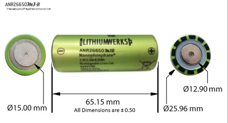
Height (max): |
65.15 (+/- 0.5 mm) |
|
Diameter (max): |
25.96 (+/- 0.5mm) |
|
Mass: |
39.5 (+/- 1.0 g) |

Battery mechanical design
The batteries are selected according to the vehicle demand and the parameters which affect selecting a battery capacity and voltage are given below.
- maximum traction motor torque
- maximum regeneration brake torque
- vehicle range
- vehicle total weight
- vehicle price
Battery design calculation
The battery energy is to be taken as 18KWh and we assume a voltage demand for electric vehicles, ie 400 Voltage.
Now we find the number of cells that make 18KWh energy.
No of cells = Total energy required from the battery / (Nominal voltage * cell capacity)
= 18000 / (3.3*2.5) = 2182
so we need 2182 cells to make it up to 18KWh as per these numbers and scenarios we decided on the series and parallel battery design. Now we need to identify the number of series and parallel connections,
The number of series connections decides the voltage so the number of series connections can find out by dividing the total voltage by an individual number of voltages.
ie, Number of series connections = 400 / 3.3 = 121.21
we round off the above number to 122. Now if we connect 122 cells in series we will get a 400V battery with 2.5Ah
Now the number of cells in parallel can be found from the ratio of the total number of cells to the number of cells in series.
ie, Number of cells in parallel = 2182/122 = 17.89
we take it as 18 so this parallel connection makes total energy of 18KWh.
Now we have several cells in series and in parallel we can take cell architecture as 122S18P.
The total capacity of battery pack = 2.5 * 18 = 45 Ah
We have already calculated battery capacity which is 45 Ah means it is going to supply 45 A current per hour. which can be considered as C-rate.
If we take a powertrain consumption to be 100 wh for a Km distance then we can able to find out the range of the particular electric vehicle
ie Range = total energy / 100 = 18000/100 = 180 Km
For the enclosure box design, we take 122 series cells divided into 2 and each box consists of 61 cells, now 2 boxes of series connection make 1 module and 18 of these with parallel connections make a whole battery pack.
So to design these boxes we take,
The length of the module=No.of cell in row*(Cell dia + Margin at both side of cells) + clearance at side(2(cell dia + margin)) = 61*(26+4) +60 =1890mm.
The bredth of the module=(cell dia +Margin of both side of cells + clearance) = 26+4+60 = 90mm
Height of the module=Height of the cell + connecting strip thickness, wires say 30mm = 65 + 30 = 95 mm.
Total volume of 1 box is given by leghth * bredth * height = 1890 * 90 * 95 = 16159500 mm3 = 0.01615 M3
so the volume of total volume = 0.01615 * 36 = 0.58 M3
Total weight of battery pack = weight of single cell * number of cells = 0.076 * 2182 = 165.8 Kg
We can consider the weight of additional accessories as 5Kg then the total weight will be 170.8 Kg.
Joining technologies of cells:
Various welding techniques practice the interconnections between cells/modules. Some of them are,
- Ultrasonic metal welding.
- Resistance welding.
- Laser beam welding.
- Wire bonding.
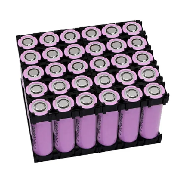
Cell Holders
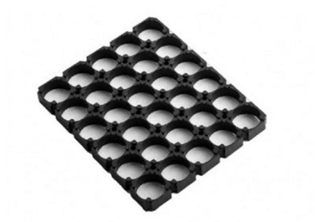
Battery Cell Spacer/Holder is a cylindrical battery spacer, made of flame retardant ABS+PC materials, with high-temperature resistance and crack resistance.
Slots on the holder's edge can be combined into many different sizes and shapes of the battery pack; after welding nickel tabs, the pack can pass the vibration test without any other connecting device. Make your battery pack Solid and Reliable! given below can be considered as an example of a cell holder with 30 cells.