Wiring harness design in CATIA V5 - 3D modeling Week 5 & 6 Challenge
Q1. Route the following harness layout in Electrical workbench. Make assumption for harness bundle diameters. Use the connectors provided. After completion of routing,
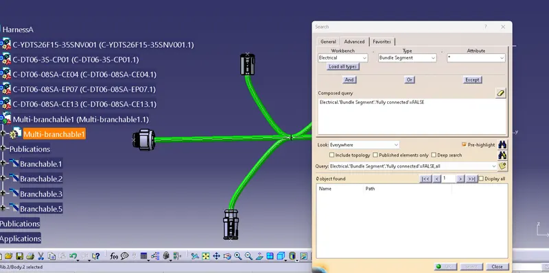
- Check the bundle Continuity. Add snap of result in submission
- Add annotation to all connectors. Make an assumptions for annotations like connect 1 , 2 etc
- Check for the bundle warning. Add snap.
- Generate CAT.part of harness assembly and convert is in. igs format.
Click here for CAD data and routing mapping data
We import all the connectors into catia V5 environment and mark points and create axes in the assembly design workbench and then change to electrical part design and define all products electrically and mark the connector connection and bundle connection points.
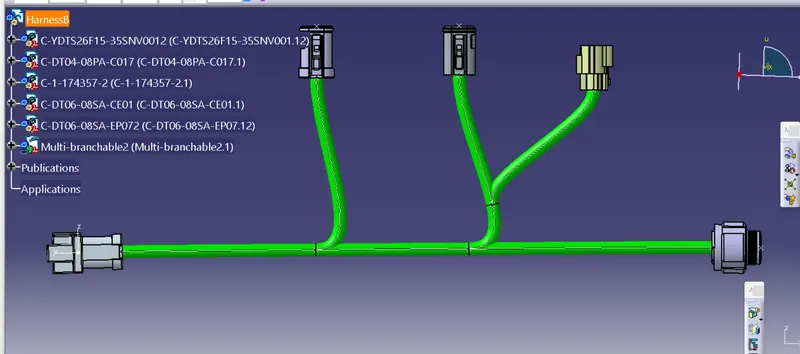
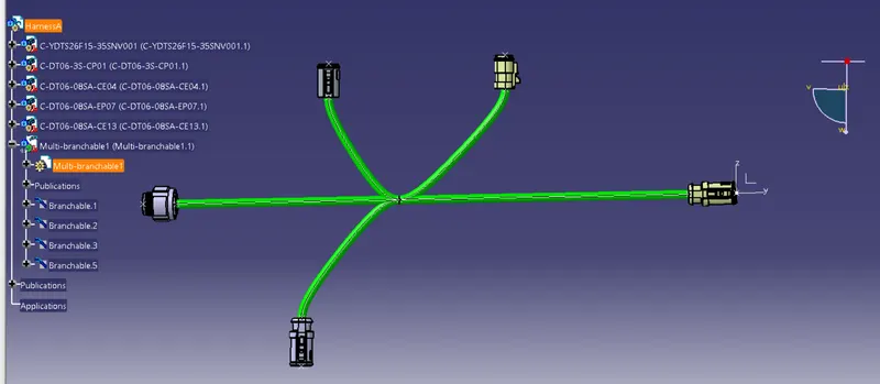
Now create new product and create harness A and Harness B in two different product sketches using an electrical harness workbench.
Harness B
Harness A
Now we check the bundle continuity using the advance search option and make sure the bundles are continued. as shown below.
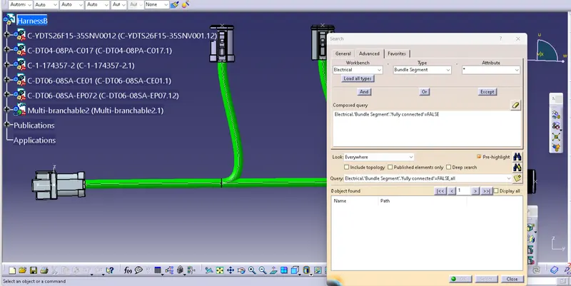
Then both harness bundles are copied to the new product and connected electrically using the electrical assembly workbench.
The annotations are made using the annotation in mechanical assembly workbench.
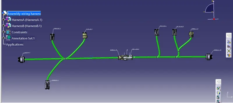
The work is first converted into allcat product file and saved in igs file format. The same is attached below .