Wiring harness routing & packaging Rules Week 3 Challenge
Q1. Download following cad data & define it as Electrical support using Electrical Part design Workbench. Define all the necessary properties.
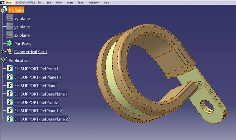
Steps
The file is introduced to catia v5 . Then switch to mechanical part design and mark 2 entry/exit points on both sides . Create a reference plane along the points and referring the p clamp planes and a base plane by referring to the base plane of p clamp. Switch to electric part assembly and Then click define support part icon and follow the lead to define the electrical properties in both direction entry.
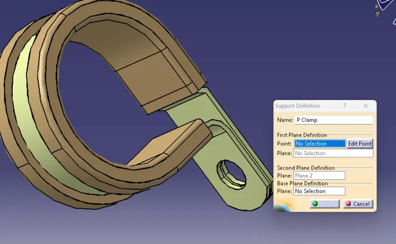
Q2. Download following Back shell cad data & define it as Electrical back shell using Electrical Part design Workbench. Define all the necessary properties.
Tyco 1738312-1 https://www.te.com/usa-en/product-1738312-1.html
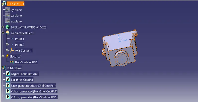
Steps
Import the part into the catiav5 environment and switch to mechanical part design and mark two points and define the axes for the connector contact . now switch to the electrical environment and define the back shell connection points which aligns exactly with the connector mating surface.
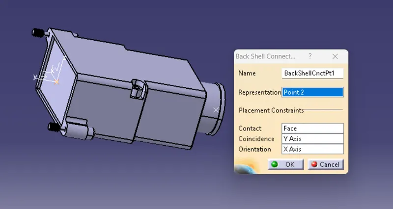
Q3. Create Following Corrugated tubes & Add them in Catalogue under “Slit COT” family.
|
Name |
ID (mm) |
OD (mm) |
Thickness (mm) |
|
15mm COT |
12 |
15 |
1.5 |
|
20mm COT |
17 |
20 |
1.5 |
|
35mm COT |
32 |
35 |
1.5 |
|
10mm COT |
7 |
10 |
1.5 |
|
5mm COT |
3 |
5 |
1 |
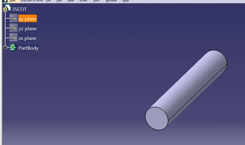
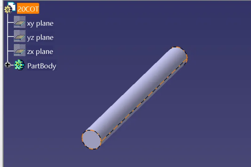
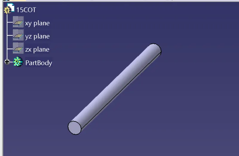
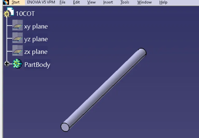
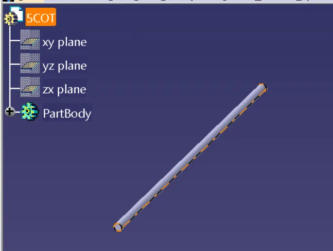
For creating these Corrugated tubes we simply create a new part in the electrical environment and click on protection devices and fill up the desired values to the tab given below
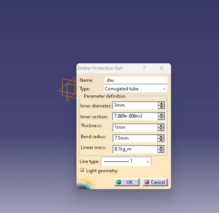
Then we create a new catalogue in the family name of slit cot and add these corrugated tubes to that catalogue