Project 1
ENGINE WIRING HARNESS
AIM :
- Create Wiring Harness Routing for given V16 Engine Given.
- Application of all Packaging rules.
- Apply Protection coverings as required.
DESCRIPTION :
WIRING HARNESS :
Automotive wiring harness is defined as an assembly of wires, terminals, and connectors that run throughout the vehicle to transmit information and electric power. Automotive wire harness is designed according to electrical & dimensional requirement of automobiles and is integrated to connect different parts of vehicle such as body, engine, dashboard, chassis, and others. Automotive wiring harness enables transmission of control signals and electrical power to electronic & electrical devices in an automotive to ensure basic functionality & enhanced safety.
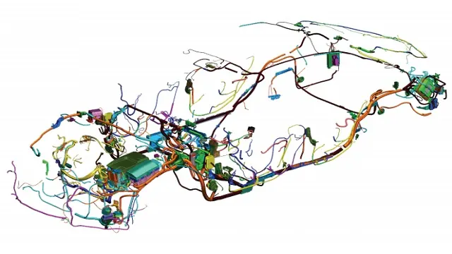
Development of vehicles with advanced safety features and technological advancements drive the growth of the market. Rise in adoption of electric vehicles across the globe is expected to supplement the market growth during the forecast period. Installation of flexible wires in automotive wiring harness for improved power delivery and increased use of aluminum to reduce weight of wiring harness are factors expected to further boost the growth of this market. However, high maintenance cost is expected to hamper the growth of the market. Furthermore, surge in development of autonomous vehicles and proactive government regulations associated with electric vehicles are expected to offer growth opportunities during the forecast period.
PACKAGING RULES:
- Wiring harness routing shall provide ease in manufacturing, accessibility, easy removal, and easy maintenance of attached equipment and wiring harness.
- Routing through small structural holes and openings shall be avoided, minimize chaffing and handling of the wiring harness during installation.
- Avoid the harness routing and clipping in the Blind zone of the Operator during harness assembly or in service.
- Routing shall offer protection against possible damage through common misuses such as being handhold and temporary support for test equipment.
- Provide additional slack to the harness according to the surroundings and harness bending requirements.
- Ensure the routing meets the clearance requirements with different surrounding parts.
- Avoid routing over the bolts, near to the bolted joints. It may damage the harness or puncture the harness. Keep harness away from panel mounting screws.
- Avoid harness routing near sharp edges, if not possible provide protection to the harness.
- The maximum distance between two clips on a straight branch is 200mm.
- Provide Clips and clamps if the harness is going to bend at multiple locations.
- The use of too many sheet-metal brackets should be avoided.
- The branch length should be more than 50 mm.
- Min distance between clip and branching point to be 25 mm.
- Min distance between two branch breakouts should be 50 mm
ENGINE WIRING HARNESS :
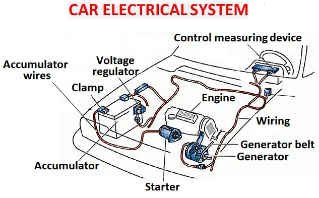
Electrical systems are becoming more and more important in automobiles. An electrical circuit can be found in every part of a modern car, from heated seats, to power windows, to computer controlled engine components. A modern car even has electrical circuits in the tires. In 2008, vehicles in the USA were required to have tire pressure monitors that would alert the driver if tire pressure was more than twenty percent off of the recommended pressure. Electrical systems will only get more important in the future with the increasing sales of hybrids and fully electric cars. The majority of automobiles today have what is referred to as a 12 volt system, although in reality a healthy battery will have about 12.65 volts. When the engine is running, the alternator will increase this charge to around 14 volts. Some hybrid cars can generate as much as 400 volts.(1) The engine electrical system includes circuits and components such as the battery, alternator, and devices used for ignition and engine control. Engine electrical wires fall under two categories, primary and secondary. Primary systems are the low power systems, 16 volts or less, and secondary wiring carries the higher amperages to be found under the hood. These high amp wires include the spark plug wires and the wire that goes from the distributor cap to the starter coil. The other wires that attach to the starter coil are low voltage primary wires. The higher voltage is created inside the coil. The positive wire that attaches to the starter is also a secondary wire. Starters draw heavy amperage loads. The starter circuit is the only circuit in a car that is not fused. Secondary wires that contain higher voltages should not be tested with a meter that is not designed for the load. They can be recognized by their large diameter.
PROCEDURE:
1. Create Context File
2. Develop Geomentrical parts
1. Create Maste File :
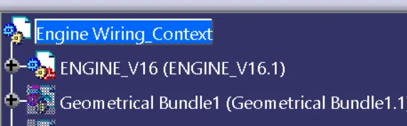
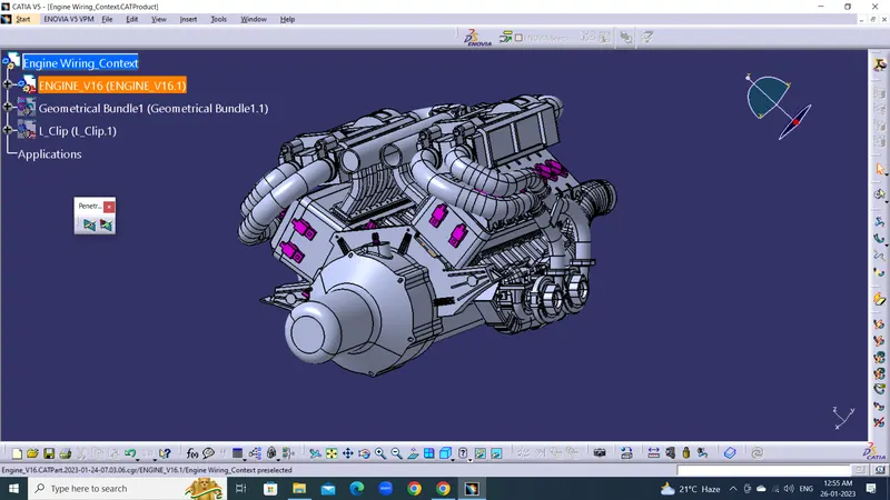
Create a master product file(Engine Wiring_Context) and two sub-level product files named Geometrical Bundle & ENGINE FILE respectively.
2. Develop Geometrical Bundle :
1. Define All Parts are Electrically.
2. Connectors Positioning.
3. Bundle Creation.
4. Protection Covering.
(A) PROCEDURE FOR CONNECTOR DEFINE A ELECTRICAL PART CATIA V5 :
- Create Geometrical Parameters.
- Define Part as Connector.
- Define Bundle Connection piont.
- Define Connector Connection point.
- Define Cavity Connection point.
1. Create Geometrical parameters :
1. Create a point on face Bundle entry area represent name as bundle connectionpoint.
2. Create a point on face Connector meating side represent Name Connector Connection point.
3. Create a Connector Connection axis referance of point which Connector connection point.
Note : In axis system The Y-Axis should be Meating direction and X-Axis Should be Locking position.
2. Define Part as Connector :
After Create geometrical parameters file change into the Electrical part design.
1. Define Part as Connector select the Define connector option in Electrical Device Defination tool bar.
2. In Connector definitaion Type should be Single insert Connector, part name as per requirement and number of terminations are how many Bundle placed in the connecto thea number .
3. Define Bundle Connection Point:
1. Select the Bundle Connection point in the Electrical connection point definition tool bar.
2. Representation and intial condition is the face which is Bundle entry and point is the Bundle connection point
4. Define Connector Connection point :
1. Select the define connector connection point in the Electrical connection point definition tool bar.
2. Representation is Connector Connectio point Contact is Face which Meating at connecton Coincidence is the Y-Axis Meatining direction and Orientation is the X-axis Locking position.
CONNECTORS USED :
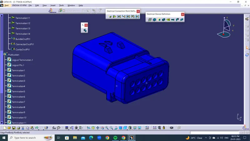
1) PART CODE : C-776438-4
QTY : 1 No
No. Of. Terminations : 14 no's
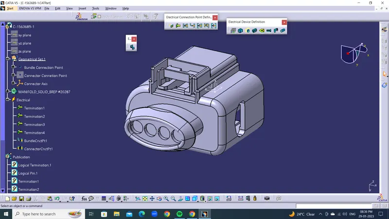
2) PART CODE : C-1563689-1
QTY : 20 No's
No. Of. Terminations : 4 no's
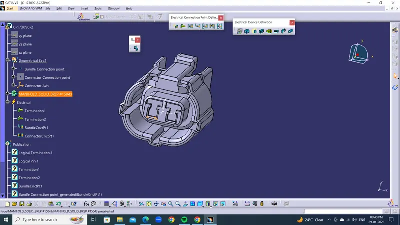
3) PART CODE : C-173090-2
QTY : 1 No
No. Of. Terminations : 2 No's
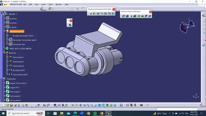
4) PART CODE : C-282087-1
QTY : 2 No
No. Of. Terminations : 3 No's
(B) PROCEDURE FOR CLIPS & CLAMPS DEFINE A ELECTRICAL
1. Define Geometrical Properties.
2. Define Electrical support.
1. Define Geometrical Properties :
Create Points and Planes For 1st Entry and Second Entry, Add Support Planr aso fot Base support.
2. Define Electrical support .
After apply geometrial properties open Electrical part design work bench.
1. Select Electrical Support definition in Electrical part design.
2. Select 1st Entry Point and entry plane exit plane and support plane.
3.Define 2nd entry electrical support select 2nd entry point & Plane and exit is defult.
CLIPS & CLAMPS USED :
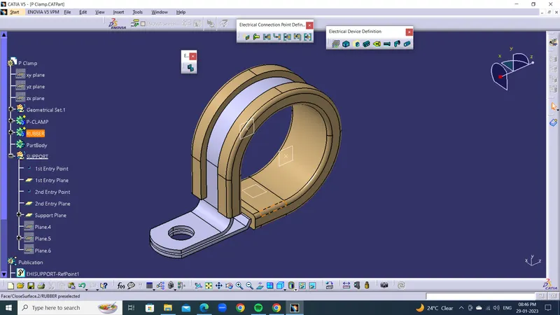
1) P-CLAMP
QTY : 3 No's
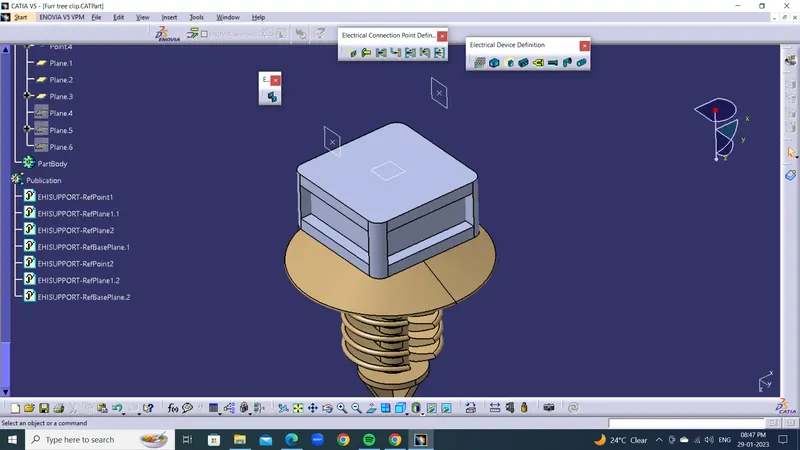
2) Furr tree Clip
QTY : 3 No's
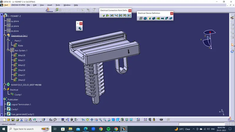
3 ) C-1924487-2
QTY : 1 No
(C) PROCEDURE FOR MULTI BRANCH CHANNEL DEFINE A ELECTRICAL
1. Create Bundle Geometrical Points.
2. Define Equipment
3. Define Bundle Connections Points
1. Create Bundle Geometrical Points.
1. Create a point on face Bundle entry area represent name as bundle connectionpoint.
2. Create a points on Channel for Sub branch Entry points.
2. Define Equipment
To be Define a Channel Electrically select Define Equipment command on Electrical Define Deinitation.
3. Define Bundle Connections Points :
1. Select the Bundle Connection points in the Electrical connection point definition tool bar.
2. Representation and intial condition is the face which is Bundle entry and point is the Bundle connection point.
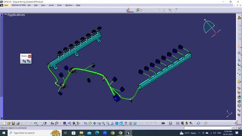
3. PROCEDURE FOR GEOMETRIAL BUNDLE ASSEMBLY:
1.Add reqquired CONNECTORS , CLIPS, CLAMPS, and Mountaining Eqipments.
2. Ensure all connectors are Electrically Defined.
3. Place the Connectors given connection segments in the Engine.
4. Add the Supporting features like Clips & Clamps desired postion of Bundle routing.
5. Add Guiding Channel and place desired position in the engine For channel Define it as Define Equipment in Electrical part Design Work bench.
6.Give the Bundle connection point to the channel (on both ends and at the channel guide ways). If channel is supplied along with the wiring harness, then it has to be in the Geometrical Bundle harness Assembly.
7. Affte Devlop the positins and places of parts now enter the Electrical Harness Instalation and Define the Assembly into Bundle Segment Defination.
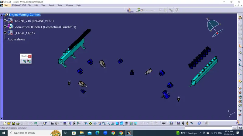
8. Now Assembly file Ready for Create Bundle Defination.
9. Create Bundle for one part to other part main Branch Dia of 12 mm. add Branch points for crating the Sub Branchs of wiring harness.
10 Create Sub Branchs with Dia of 10 mm and part Branchs Dia of 5mm.
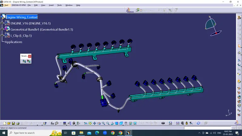
4. Protection Covering :
Add Protectiove tubes for Safety and Bundle Holding purpose from Catalog Files.
CHECK BUNDLE CONTINUTY :
Go to Edit, Select the Search, in search go to Advance. In Advance, in workbench select the Electrical, in Type select the Bundle Segment, in Attribute select the Fully Connected option.
FLASE STATEMENT
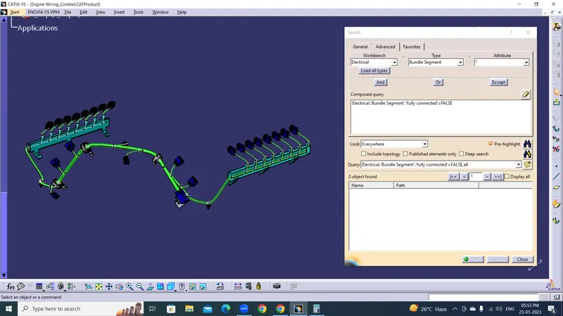
RESULT : NO open BUndle
TRUE STATEMENT
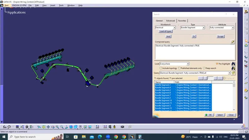
RESULT : All Bundle are Connected.
WIRING HARNESS FLATTENING
Harness Flattening tool enables users to flatten 3D geometric harness data exported from supported MCAD systems. It prepares the flattened harness structure for import into E3. formboard where the manufacturing detail can be completed. MCAD systems enable mechanical engineers to model their products in 3D.
Harness Flattening tool enables users to flatten 3D geometric harness data exported from supported MCAD systems. It prepares the flattened harness structure for import into E3. formboard where the manufacturing detail can be completed. MCAD systems enable mechanical engineers to model their products in 3D.
PROCEDURE :
1. New Product File
2. Setting Harness Flattening Parameters
3. Extract File
4. Flatten and Develop
1. New Product File :
Open catia V5 and opened a new product file and already created wiring harness assembly routing.Rename the product file into a 'Wiring Harness _Flattening'.
2. Setting up the flattening parameters:
- Switch to the Electrical Harness Flattening.
- Select the command called Harness Flattening Parameters.
- In general tab, change the minimum angle distance between them to 5 degree.
- Enable, keep existing tangent between bundle segment and connector during the flattening step.
- Also enable, Extract only the supports inside the geometrical bundle.
- Select the Radius of the bundle segment for the Roll radius for Quick roll.
- Keep the parameters default or change according to our requirement.
- Save this file as a Fattening product in the path where the required wiring harness assembly file is located.
3. Extract:
- Opened the wiring harness assembly file and tile the window vertically.
- Select the Flattening product file in model tree and select the extract command in Electrical Harness Flattening workbench and select the wiring harness assembly file to fetch the required information.
- Now the wiring harness assembly file details are extracted into the flattening product.
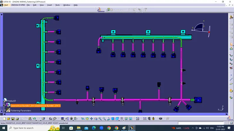
4. FLATTENING & DEVELOP :
- Now select the Flatten command in Eletrical Harness Flattening Workbench.
- Select the active plane as a required surface or any other required planes.
- Keep default parameters in Algorithm mode and Angle mode.
- Select the branches and select ok to perform the Flatten operation.
- Use the other commands such as rotate, roll, straighten and synchronization for the alignment of Flattening product.
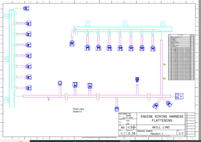
Creating 2D Harness Flattening Drawing File.
- Open the new drawing file and save as a Harness Drawing File.
- Keep ISO as a standard and A0 ISO as a sheet style.
- And select Landscape.
- Now select the Front view command in Drawing file and select the required surface or the plane for view in the flattening product file.
- Now the flatten product details are delivered into the drawing file in a 2D.
- Now go to the properties and select the view tab, under dress up section, enable the 3D colors (if needed) and also enable the 3D wireframe is always visible.
- Now the full details of flatten product details are obtained in a 2D form.
https://drive.google.com/drive/folders/1lXYutNpCdbGJUeCBy0TA93in9CpY5wS-?usp=share_link
- Now the connectors are represented in a 2D. So we can change the representation into 3D by changing the flattening parameters in the flattening prodct file.
7 CONCLUSIONS
- The wiring harness basics and the industrial practices are studied.
- Different connectors and their installation in 3D modeling are practiced.
- The protective devices and their application at the required region in the wiring harness bundle are practiced.
- Electrical workbenches in CATIA V5 such as electrical part design, electrical assembly design, electrical assembly harness, electrical harness flattening are exercised.
- 3D representation and 2D drawing of the engine harness are implemented.
- Engine harness is taken as a case study and developed the geometrical bundle assembly without fouling the bundle segments.
NOTE :
https://drive.google.com/drive/folders/1lXYutNpCdbGJUeCBy0TA93in9CpY5wS-?usp=share_link