Week 9 - Project - A pillar Design with Master Section
A-PILLAR :-
AIM :
1. To be able to develop A-PILLAR given Class a Surface and add B-side feature Dog House using master sections.
2. Draw a Propar Main axis and Side Core axis and Perform Draft angel analysis CLASS A SURFACE and A-PILLAR Body.
DESCRIPTION :
MASTER SECTIONS : -
Master sections are the guides for design requirements which decide the component packaging after technical (Styling, Concept or Class-A) surfaces.
Concept development in BIW
Concept & Feasibility
•Concept design / Design support and feasibility study
•Concept surface description
•Generate master sections and component packaging
•Technical surface description (A class)
•Deciding part configuration / split lines
•Gap & Flush requirement
•Feasibility study & simulations
•Assembly sequence & develop process diagram & spot plan drawings
•Preliminary weight analysis and bill of material
Package analysis
•Interior, exterior, engine, underbody, and luggage compartments
•Engine and passenger compartments
•Closures
Detail Design
•Modeling & drafting of vehicle components
•Sub assemblies & assemblies: Body in white, closures
•Tolerance analysis
Facelifts and Variants
•Minor freshening: rub rails, door trims, steering wheels, roof carriers, and decorative trims
•Moderate facelifts: bumpers, spoilers, grilles, steering wheels, door trims
•Mid-life facelifts: changes in bumpers, lamps, instrument panels & consoles, spoilers, grilles, steering wheels, door trims, new engine, RVMs, BIW changes to suit trim changes
•Major Facelifts: carryover platform
•Variants: from base hatch back platform to sedan and station wagon with or without W/B increase
Engineering Documentation
•Bill of Material generation and controlling
•Material specifications
•Chain of Dimension, Gap and Flush study and GD&T on drawings
•Design Failure Mode Effective Analysis (DFMEA)
•Product specifications, Design Validation Plan (DVP)
•Fastener selection
3D-engineering, 2D-drawings releases
•Body contour development
•Design according to tool, manufacturing or process requirements
•FMEAs
•Data management and Releasing
Geometrical Integration / Digital Mock Up (DMU):
•Package
•Collisions-check
•Design studies
PROCEDURE :
1. Define a CLASS A SURFACE check any patch or open profile given surface.
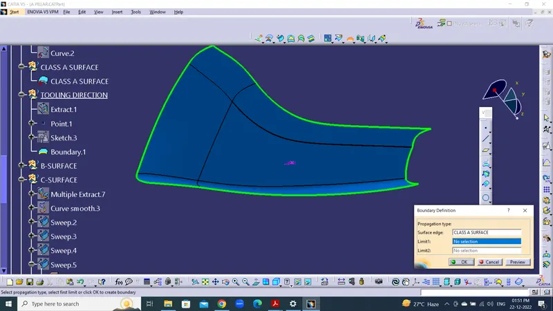
2. MAIN TOOLING AXIS :
Tolling Direction is main consideration for plastic part and mold parts because it Define movement of mold part and possibility of plastic part come ou from core and cavity
1. To Create main Tooling axis select positioned sketch orgin referance is point of extract surface.
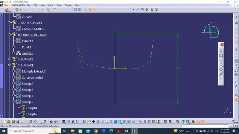
2. Select the command intersect 3D elements and select the CLASS A SURFACE draw a lines reference of intersect profile.
3. Select the Bisecting line referance of lines.
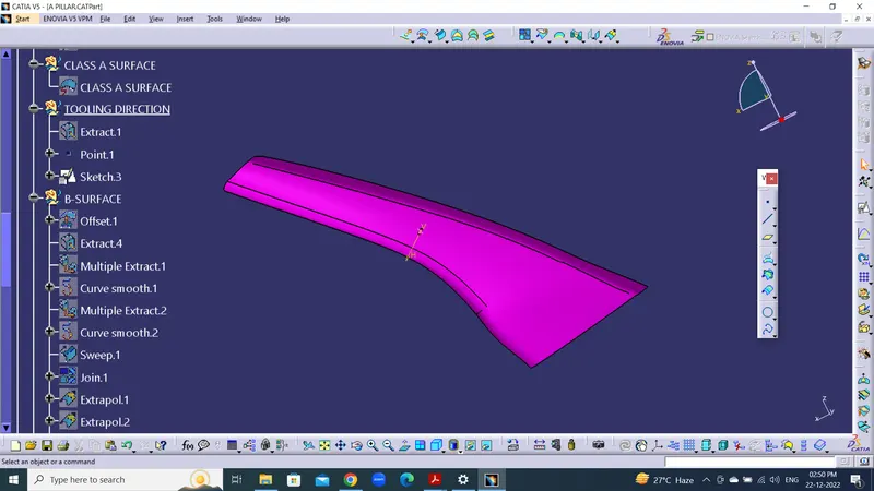
3. CLASS B SURFACE :
Offset The CLASS A SURFACE 2.50 mm referance of master section. Develop Missing the features use Extrudu, Sweep, Fill, multisection surface, Blend and develop feature Join, Smmoth surface, Extract, Multi Extract, Fillet.
Extrapolate 10mm all edges of B-SURFACE .
4. C-SURFACE :
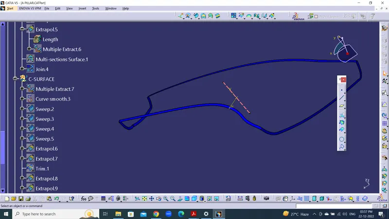
To Create a C-SURFACE by using Sweep, Blend, Multisection Seurface and Fill devlopming feature Join, Spilt, Trim, smmoth Curve and Extrapolate devlop referance of CLASS A SURFACE 87°
5. FINAL SURFACE :
To create Closed surface First join the CLASS A SURFACE and C-SURFACE.
Final attachment a Closed Surfacce Trim the Joined Surface and CLASS B SURFACE.
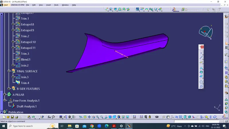
Note : Check The Closed Surface any patch or cut in surface.
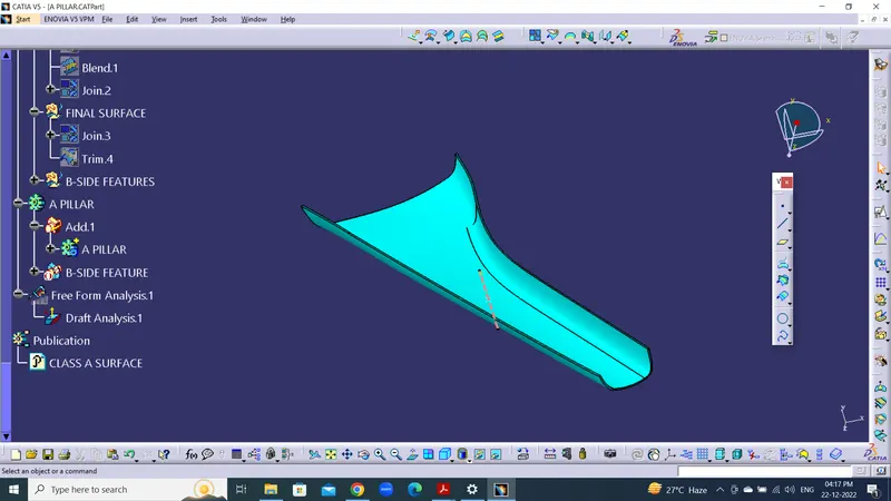
6. BODY :
To Create a solid model use of closed surface command in Part design.
7 . B-SIDE FEATURES :
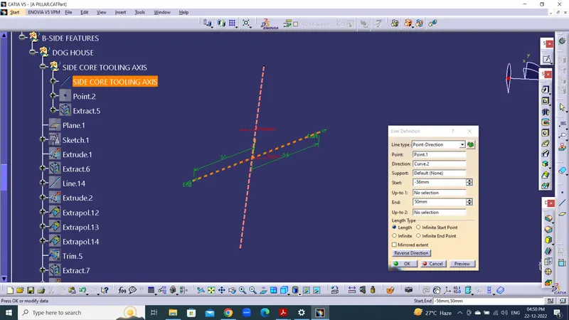
SIDE CORE TOOLING AXIS :
To Create side core tooling axis perpedicular main tooling axis referance of Maset section.
DOG HOUSE :
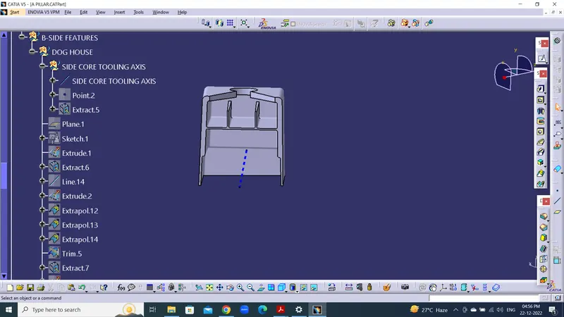
To Develop a B-side features of A-PILLAR referance of MASTER Sections.
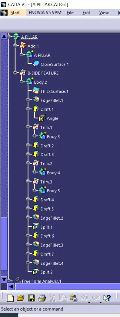
1. To create a Dog house referance of Master section. first Create Surface of Doghouse and Thicken the surface referance master section
2. Draft the Dog house inside 1.5 degree. and develop the other features in dog hose main part.
3. Devlop a flange part on rib section and add the Dog hous main feature.
4. Devlop the Bottom area of Doghouse Wirh Design Rules.
8. ADDING B-SIDE FEATURES:
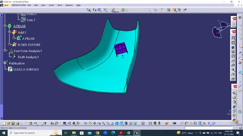
Add the Dog house to main Body of A-PILLAR By using add, Intersect, Union Trim and assembly Command .
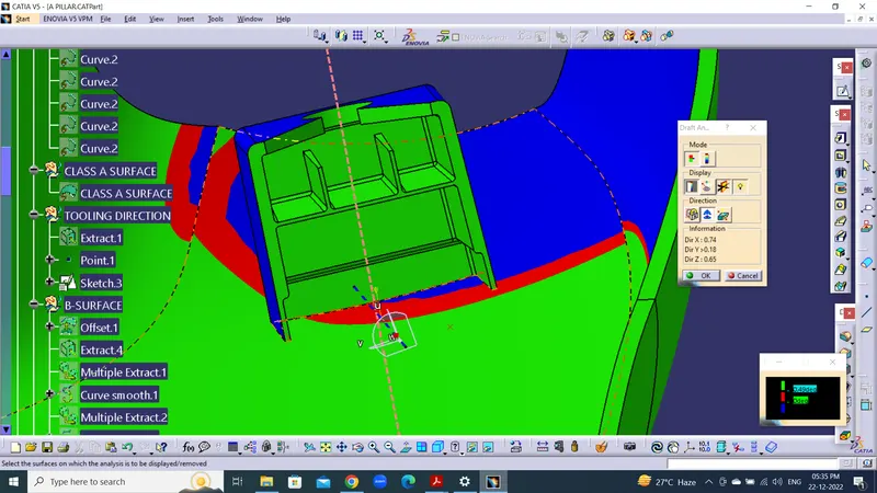
9. DRAFT ANALYSIS :
The draft analysis technique is used to analyze whether our part model created in CAD is manufacturable based on the draft condition applied. Here the part should get easily removed from the panel dies (in case of Sheet metal part) or Mold (in case of plastic).
No parts can be ejected from the tool if it is having a straight 90-degree profile from its base surface. A small draft angle is provided to each and every area of the component in order to get easy removal of the component from the tool.
Here we are providing a direction in which components should eject in order to get easy removal of components from the tool. In other words, it also lets us know whether the model is having a draft angle and how much is the draft angle from the tool direction.
We Perform two Draft Analysis 1. Main Draft analysis and 2. Side Core Draft Analysis.
1. Main Draft analysis perform body to select main tool axis and Degree to be 3° make sure all c-surface should be above 3°.
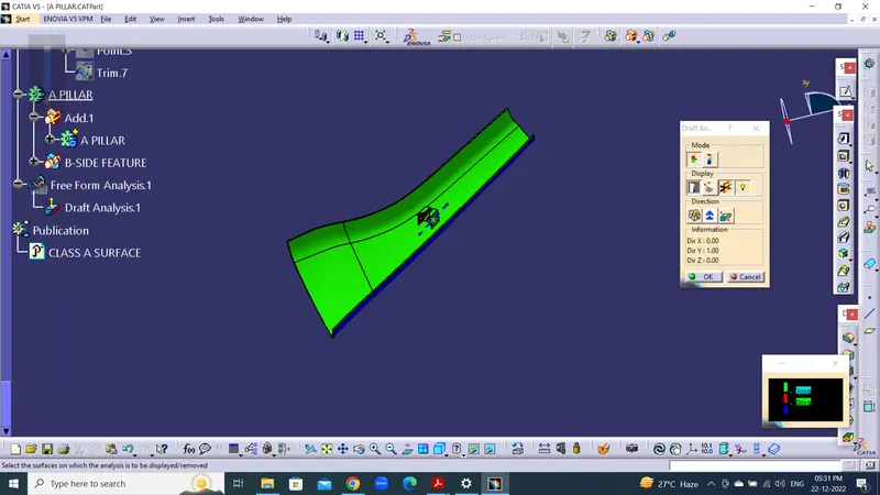
2. To Perform Draft analysis for Side Core select the Side Core tool axis and and value should be 0.50º all should be 0.50°.
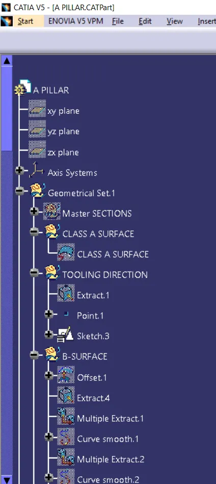
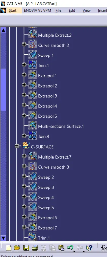
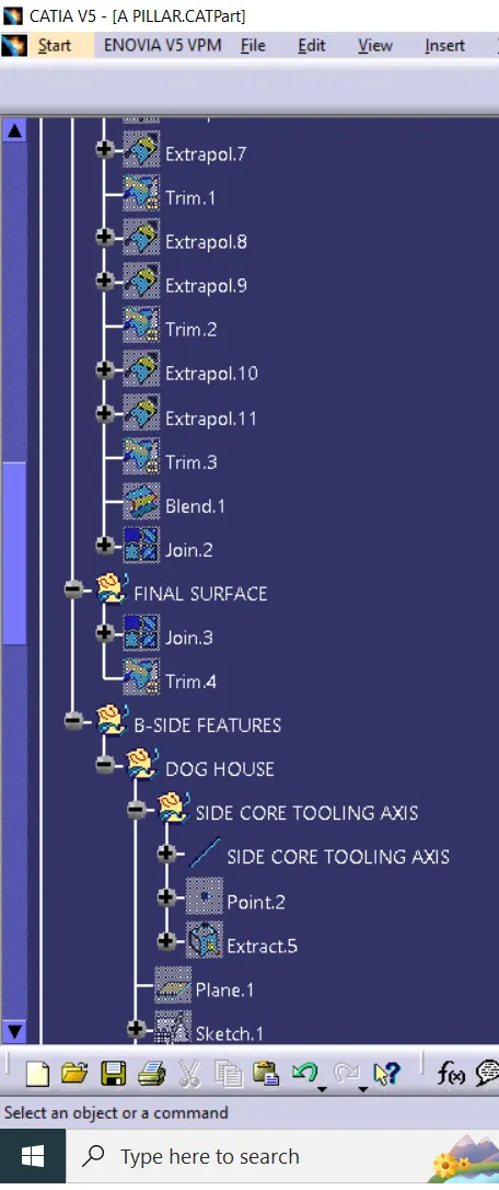
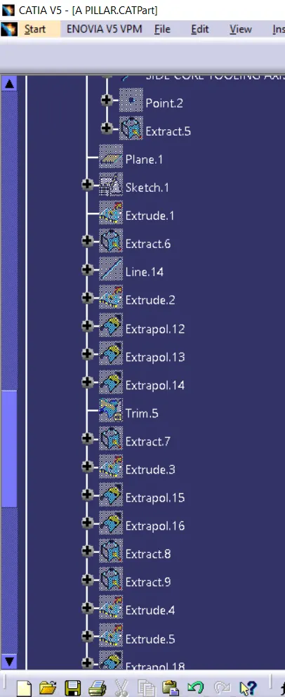
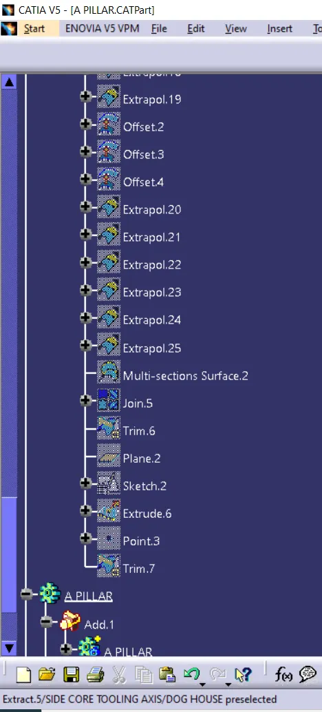
TREE STUEUCTURE :