Design of backdoor
BACK DOOR
AIM :-
To Develop the CAR BACK DOOR wtih reference of give CLASS A Surface as per OEM standard in CATIA.
INTRODUCTION : -
Back door is also called as tailgate. Back door in a car gives the access to luggage area and few cars have passenger compartment too.
In most of the cars gas stay is used to operate the back door. Few cars have electric motor to lift the back door when a switch is pressed.
The parts of the car and has mounts for tail lamp, hinges, wiper motor, gas stay etc. Back door is made up of 1 inner panel and 2 or 3 outer panels joined together by hemming and spot welding process.
MATERIAL
The Aluminium or Steel used for manufacturing the back door. Procedure for manufacturing of BIW in automotive.
Aluminium : The aluminium parts are casted in biw sheet metal. The purpose of using aluminum is, it is having less density, so the final weight of the product will be very small. So, we cast the part which means we vary the thickness on different regions so I avoid the reinforcements completely.
Steel : The Steel part are Stamped in BIW Steel Metal. in Steel material has uniform thickness. Reinforcements are nessery in Steel. The cost materilal very low comapare to Aluminium.
Difference Between Aluminium & Steel Parts.
| S.No | Aluminium | Steel |
| 1. | Aluminium Parts Are casted. | Steel parts are Stamped. |
| 2. | Reinforcements can be neglected. | Reinforcements are necessary. |
| 3. | Local Thickness Can be varied. | Has only uniform thickness. |
| 4. | Lighter in weight | Heavier in weight. |
| 5. | Less No of parts required | More no of Components required. |
ASSEMBLY PROCEDURE :
Load Cases – General Analysis:
Fig. Load Case – General Analysis.
here are various tests that are going to be carried out for the rear door that we design. Only when it passes the test will it be considered a success in design.
The various tests are:
- Torsion and bending Test
- Abuse Tests
- Dent Tests
- Assembly Tests and
- Endurance Tests.
- In the bend test, forces act perpendicularly along the same direction at both ends, as shown in fig. above.
Target: Maximum Bending Displacement < 1>
- In the torsion test, the forces act opposite each other along the end of the door
Target:Maximum Bending Displacement < 9>
- In the abuse test, the rear door is fixed at one end and force is applied in the opposite direction; this will be repeated vice versa.
- A dent test is used to analyse the durability of a door at a particular location. After removing force at some place over the door, if the actual face of the door comes up, then it passes the test.
- While assembling the rear, there are a lot of forces that are going to be exerted over the door. If the load is too much, this is going to be analysed here in this test.
Endurance means that something happens for a long period of time. Will it be able to withstand the force for an extended period of time? these analysis are carried out
Main force Distribution Direction :
This demonstrates how forces are resolved in various directions in all of the cases, namely the bend test, torsion test, and abuse close and open case. There is a common area where all four things have too much force, namely the latch and striker reinforcement, as well as the emboss region. So, in this region, this will be attacked, and this will be the focal point where all forces will be concentrated. The plan is to resolve the forces before spreading them to the end or toward the other flanges and outside the body of the rear doors. The CAE team will determine whether or not to modify the embosses.
INPUTS FOR DESIGNINING OF BACKDOOR:
- Outer Panel - 0.75 mm
- Inner Panel - 0.75 mm
- Reinforcements - 1.5 mm
DESIGN PROCEDURE :
- Class A Surface Repair.
- Inner Panel Development.
- Create Hemming.
- Draft Analysis
1. Class A Surface Repair.
To Repair the Class A Surface of Upper Panel & Lower Panel Patchs & over Laping Surfaces & remove sharp edges.
UPPER PANEL
Upper Panel of Class A Surface is consists of over laping, Sharp Edges.
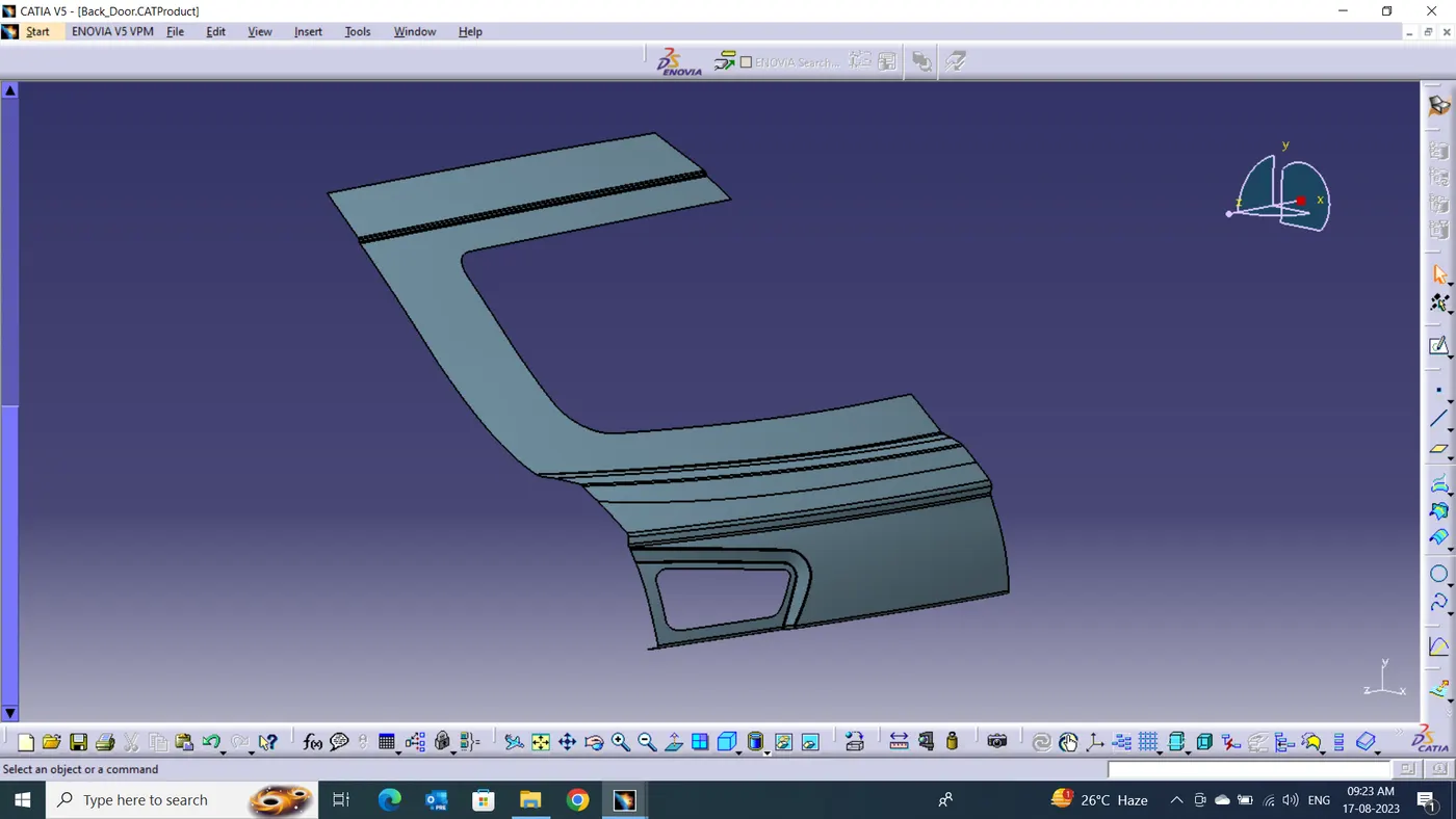
UPPER PANEL INPUT
1.Extract the surfaces of upper panel.
Note : The Extrct Surface is not in Sharp Edges
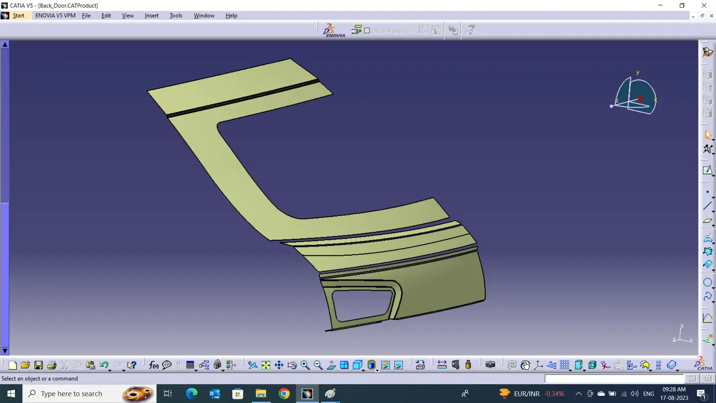
EXTRACT SURFACES
2. Find the any Over laping Surface & Sharp Corner Surfaces on Extract surfaces in Class A Surface
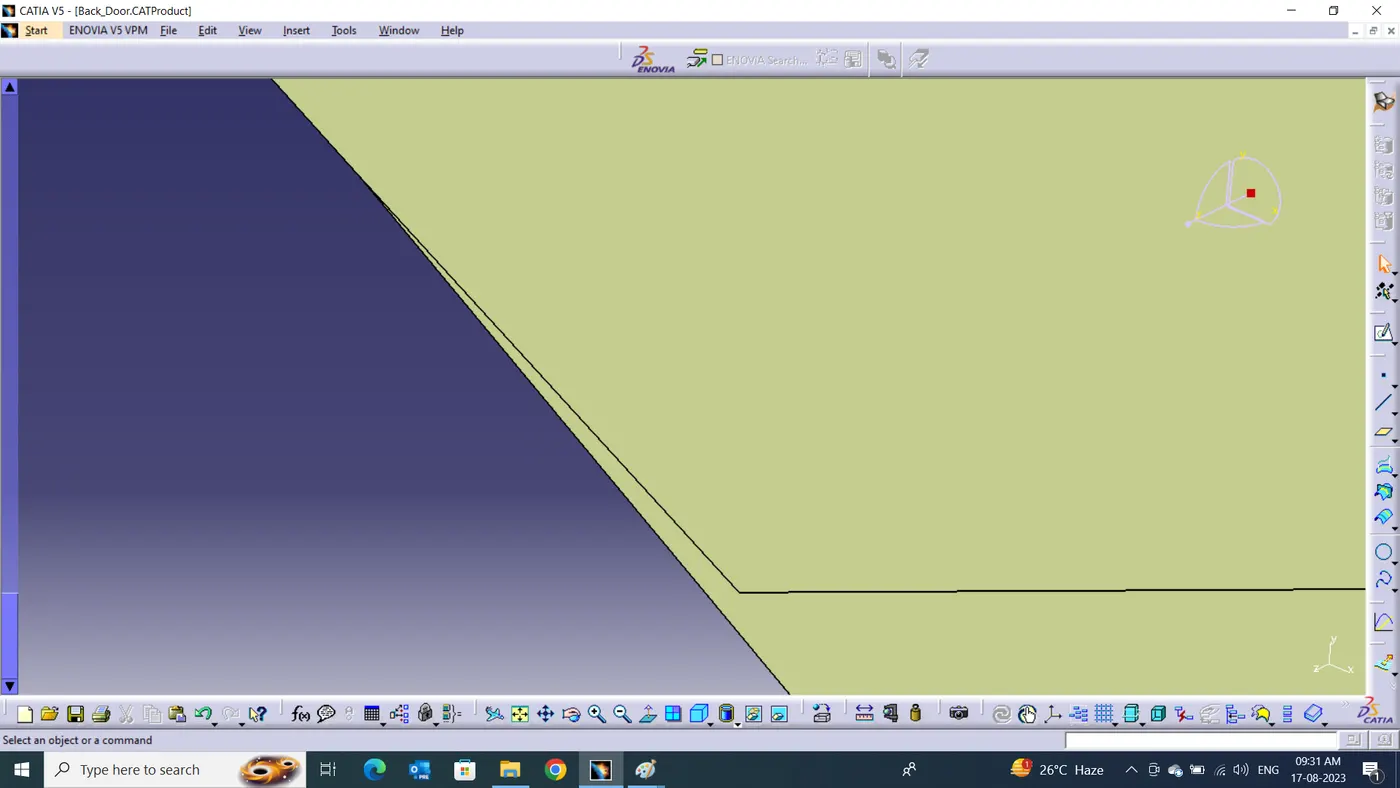
OVER LAPING SURFACE
3.To Clear the Over laping surfaces & Sharp Edges on Surfaes.
4. Develop the Surface of use of Split, Join & Trim etc
5. Give the Edge fillet of all Corner Sharp Edges.
6. Verify the Thickness of 0.75mm is to be Thicken are not Class A Surface
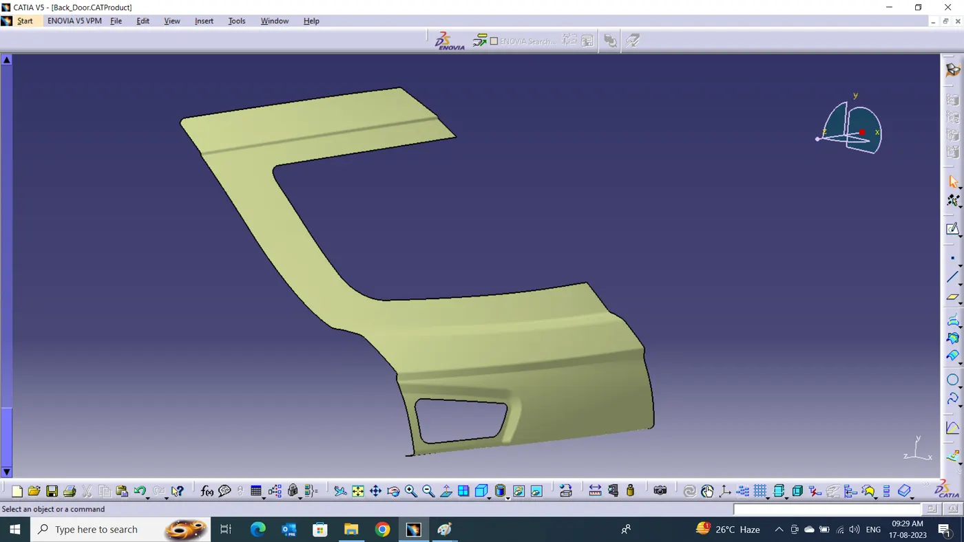
DEVELOPED SURFACE
LOWER PANEL
To Develop the lower panel.
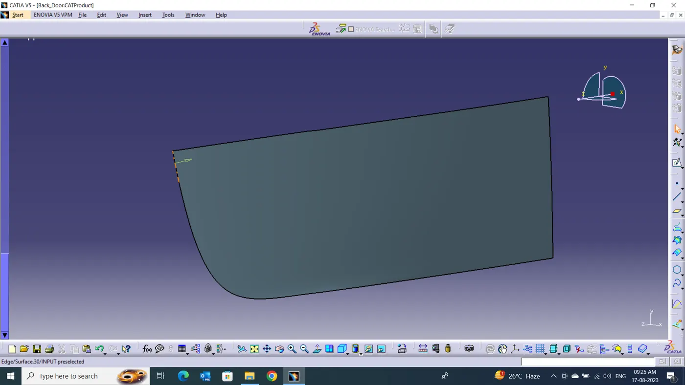
LOWER PANEL INUT SURFACE
1. Extract the surface of Lower panel & Upper panel Surface.
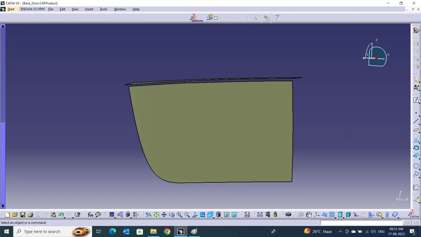
EXTRACT SURFACE
2. Offset the upper panel surface 0.2mm gap from upper panel surace.
3. Check the Lower panel surface is any sharp edge & Sharp Corner & Over Laping Surfaces.
4.Facing an issue while offset surface of Lower panel
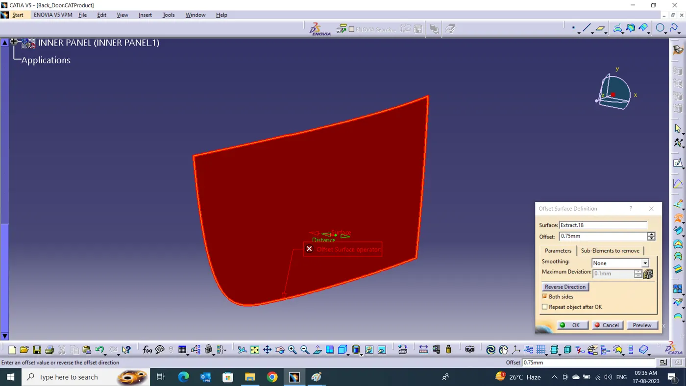
OFFSET SURFACE ERROR
5.To Solve the Offset error of lower panel surface.
1. Use Rough Offset surface give devisition value
2. Again use Normal offset surface position in normal
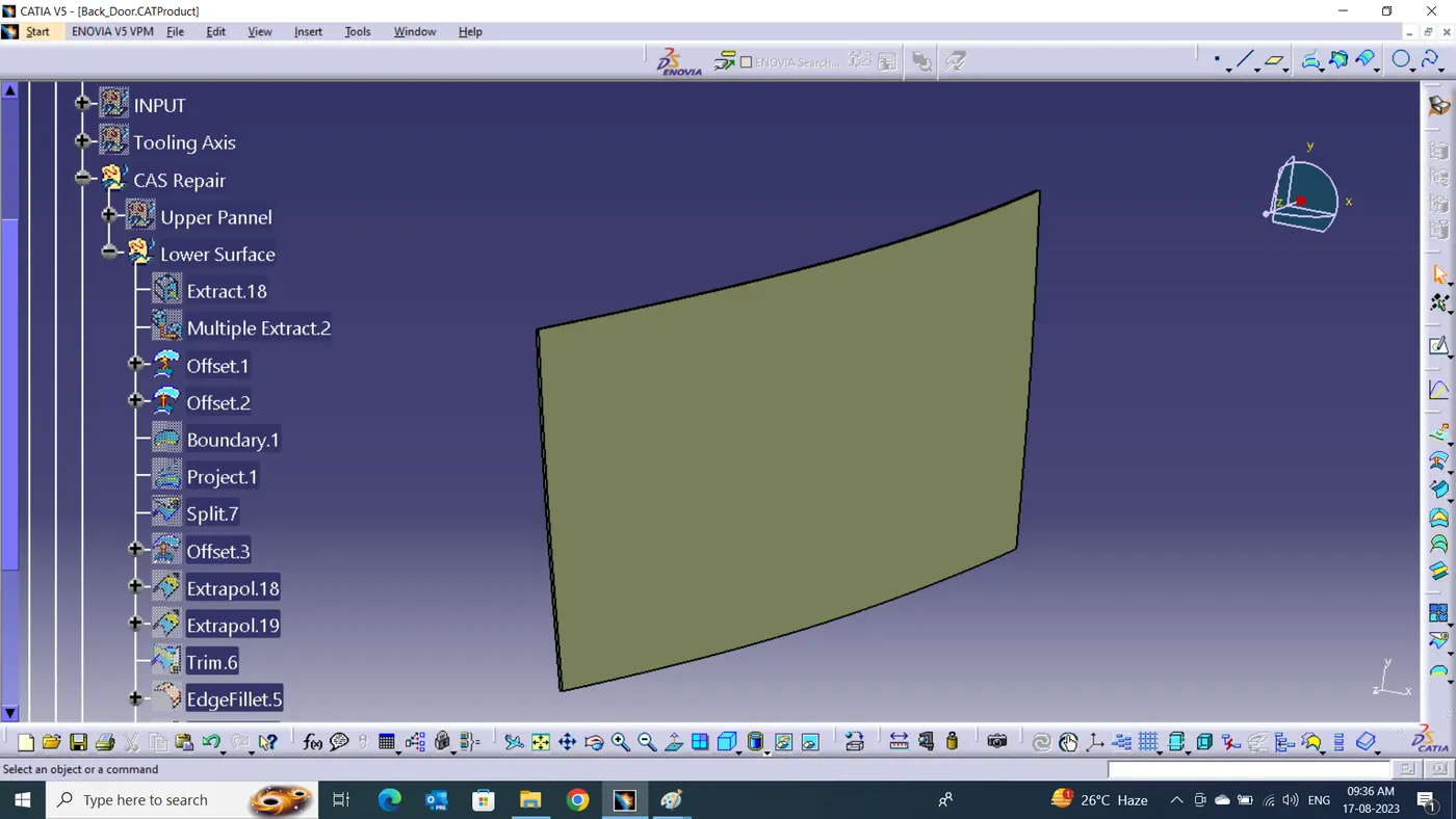
ROUGH OFFSET SURFACE
6. Split the surface with respect select boundary of Lower panel
7. Develop the surface use trim, split & join
8. Apply the edge fillet of corner sharp edge.
9. Verify with Thicken Surface of value 0.75 mm
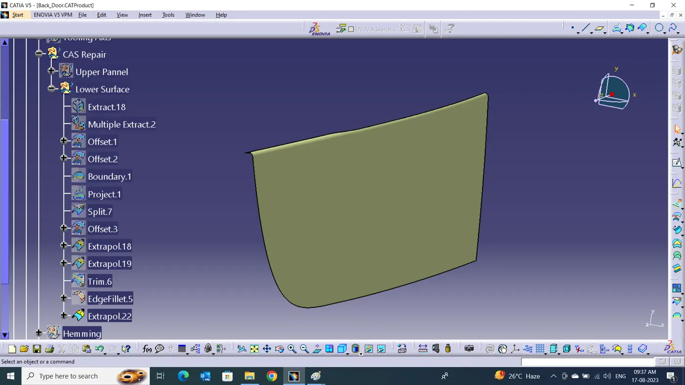
DEVELOPED LOWER PANEL
2. Inner Panel Development.
Tool Direction:
- In Sheet metal process The dies to open along direction is know as Tooling Direction.
- Seclect proper view for Visiable of Surface.
- Create lines from Bottom Center & Top to Center
- Select Bisecting Line and changed to name as the Tooling axis.
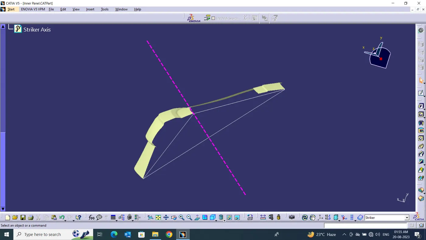
TOOLING DIRECTION
Create inner Panel
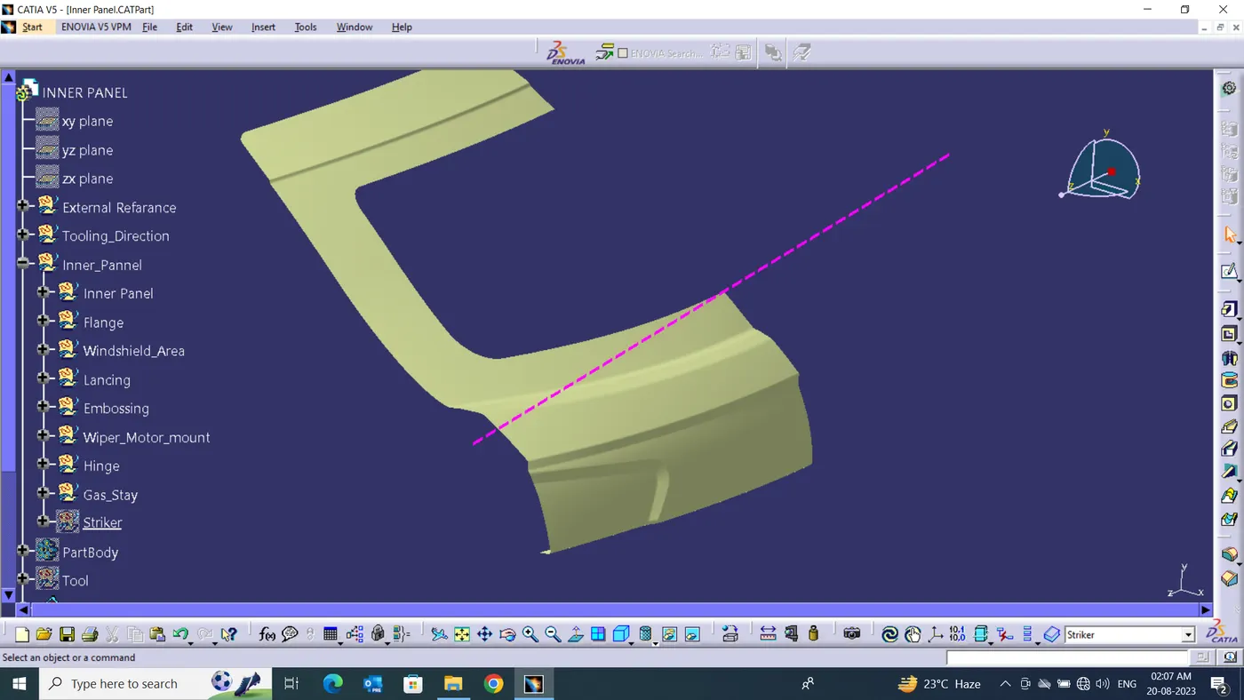
EXTRACT SURFACE
- To Create inner panel Copy Class surface in part in assembly Design.
- Offset the Reparied Class A Surface with 1.70 mm.
- Steps follow the develop the Inner Panel.
a) Sealing_Flange.
b) Side connecting_Flange
c) Windshield_Area_Flange
d) Lancing
e) Embosing
f) Wiper Motor Mount.
g) Hinge
h) Gas stay &
h) Striker.
a) Sealing_Flange :
Sealing Flange also known as Mountainge Flange. Is help for Door Mountaing on Car frame. Sealing with Rubber & lock it.
- To Create Sealing Flange on car back door Extract the required surfaces & offset the surfaces.
- Use Parallel Curve command the range from boundar 30mm to 45mm & Flange width 35mm to 40 mm
- Split Both Sides of all Surfaces & connect the surfaces with Join option
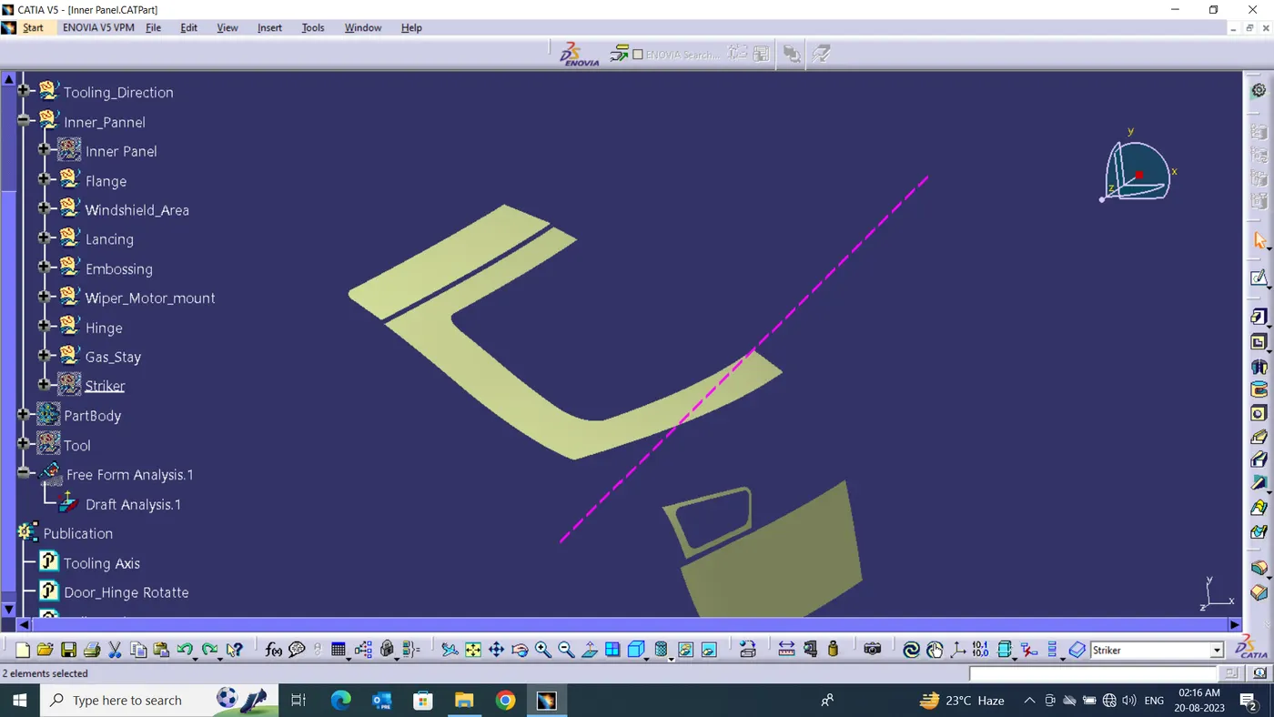
OFFSET SURFACES
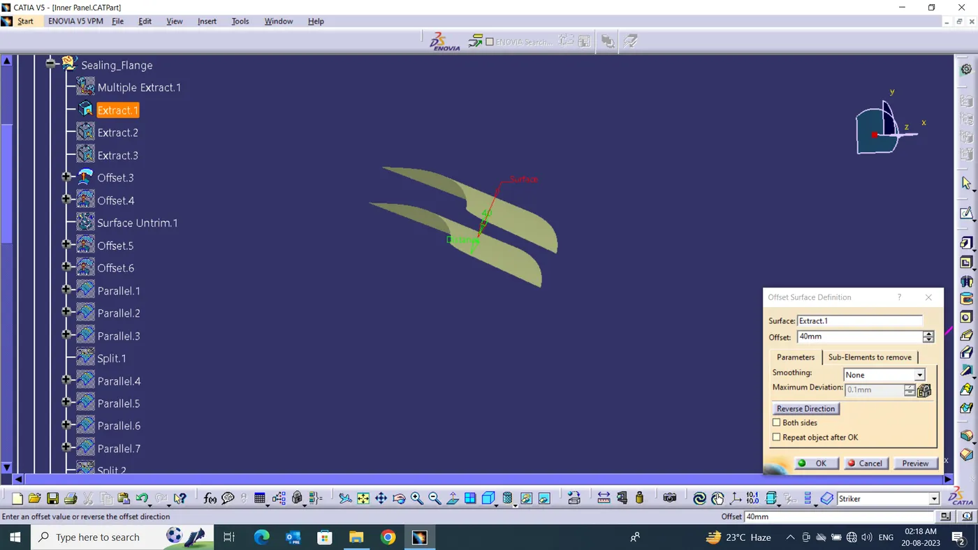
OFFSET SURFACE
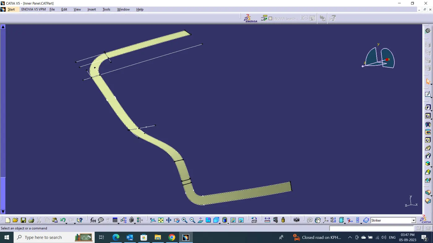
SEALINGE FLANGE
4. Join the all surfaces with no sarp edges in between the surface.
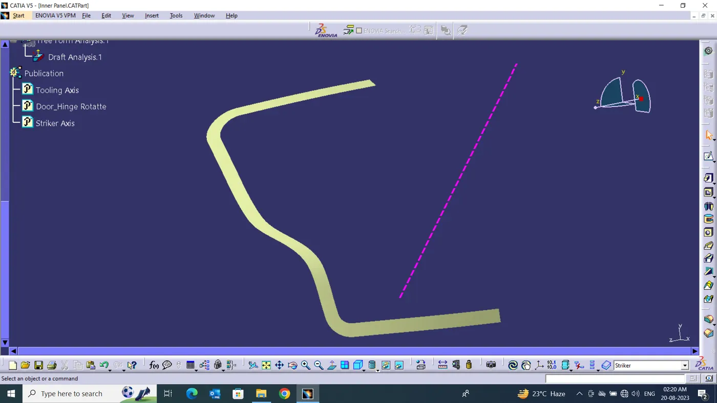
SEALING FLANGE
b) Side connecting_Flange :
Side connect flange is to be connect to the Inner panel & Sealing flange.
- To Create side sealing flange 1st select boundary with limits.
- Selet sweep option Line - with draft direction select Bowndary with reference of draft direction of tooling axis greater than 7°
- Find the sharp lines on surface and clear the shrp edges.
- Clear the shrp edges od surface use parallel curve 0.5mm on both sides of sharp line and split he surface with keep booth sides.
- Fillthe gap surfaces with select multi section surface with respect tangent & guide curve of all surfces.
- join the all surfaces of side connecting flange.
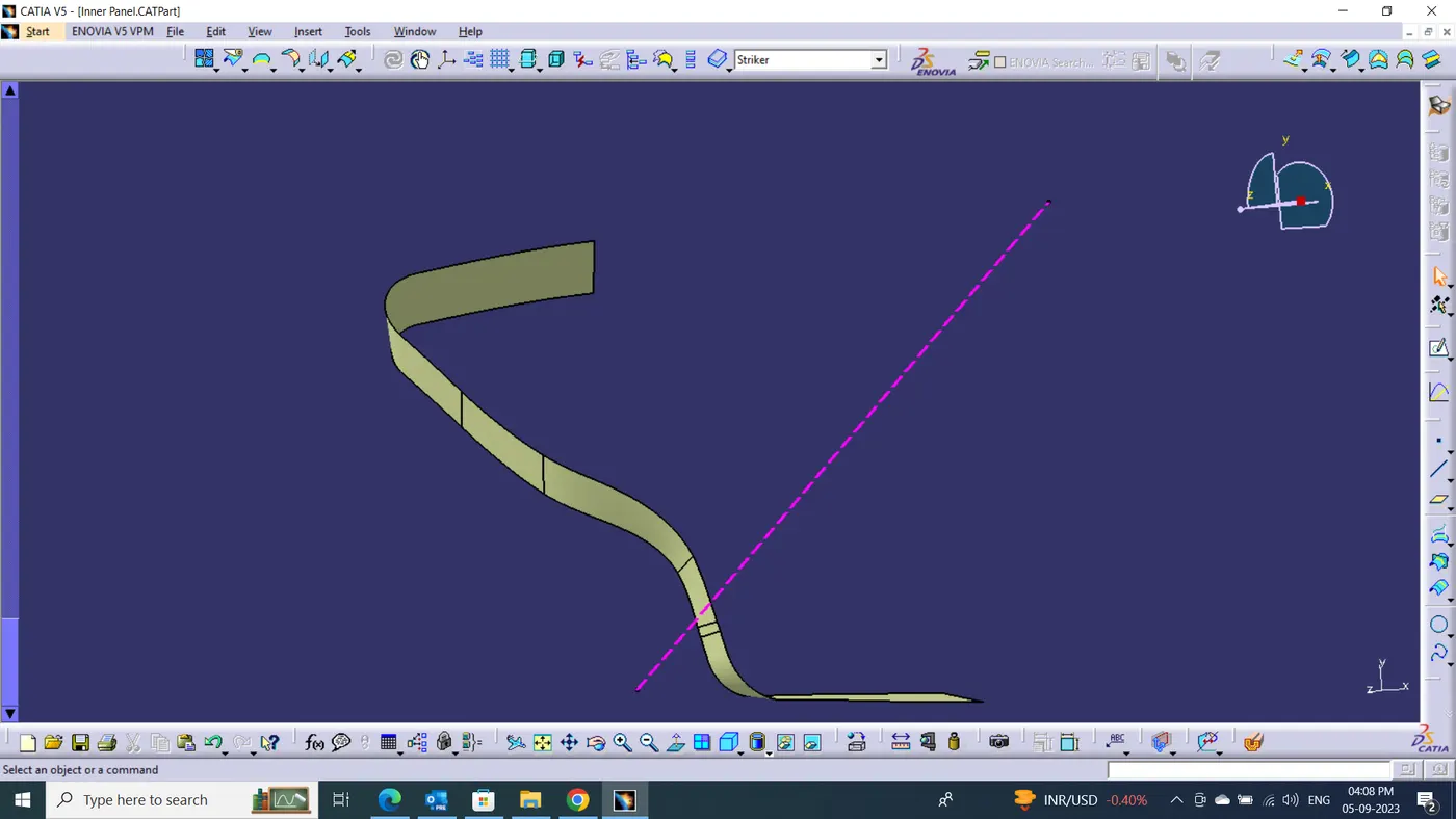
SIDE CONNECT FLANGE WITH WITH SARP EDGES
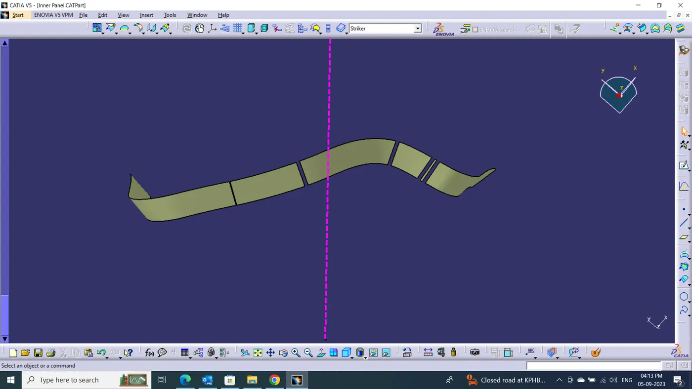
SIDE CONNECT FLANGE WITH GAPS
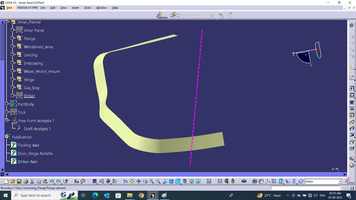
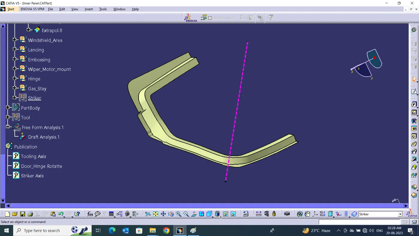
SIDE CONNECT FLANGE WITH NO SHARP EDGES
7. Connect the Side Connect Flange with Sealing falnge use of Extrapolate the both and trim.
c) Windshield_Area Flange :
Windshield area flange is to be connect to the Inner panel & Sealing flange.
- Offset Upper windshield panel direction inside.
- To Create windshield area flange 1st select boundary with limits.
- Selet sweep option Line - with draft direction select Bowndary with reference of draft direction of tooling axis greater than 7°
- Find the sharp lines on surface and clear the shrp edges.
- Clear the shrp edges od surface use parallel curve 0.5mm on both sides of sharp line and split he surface with keep booth sides.
- Fillthe gap surfaces with select multi section surface with respect tangent & guide curve of all surfces.
- join the all surfaces of side connecting flange.
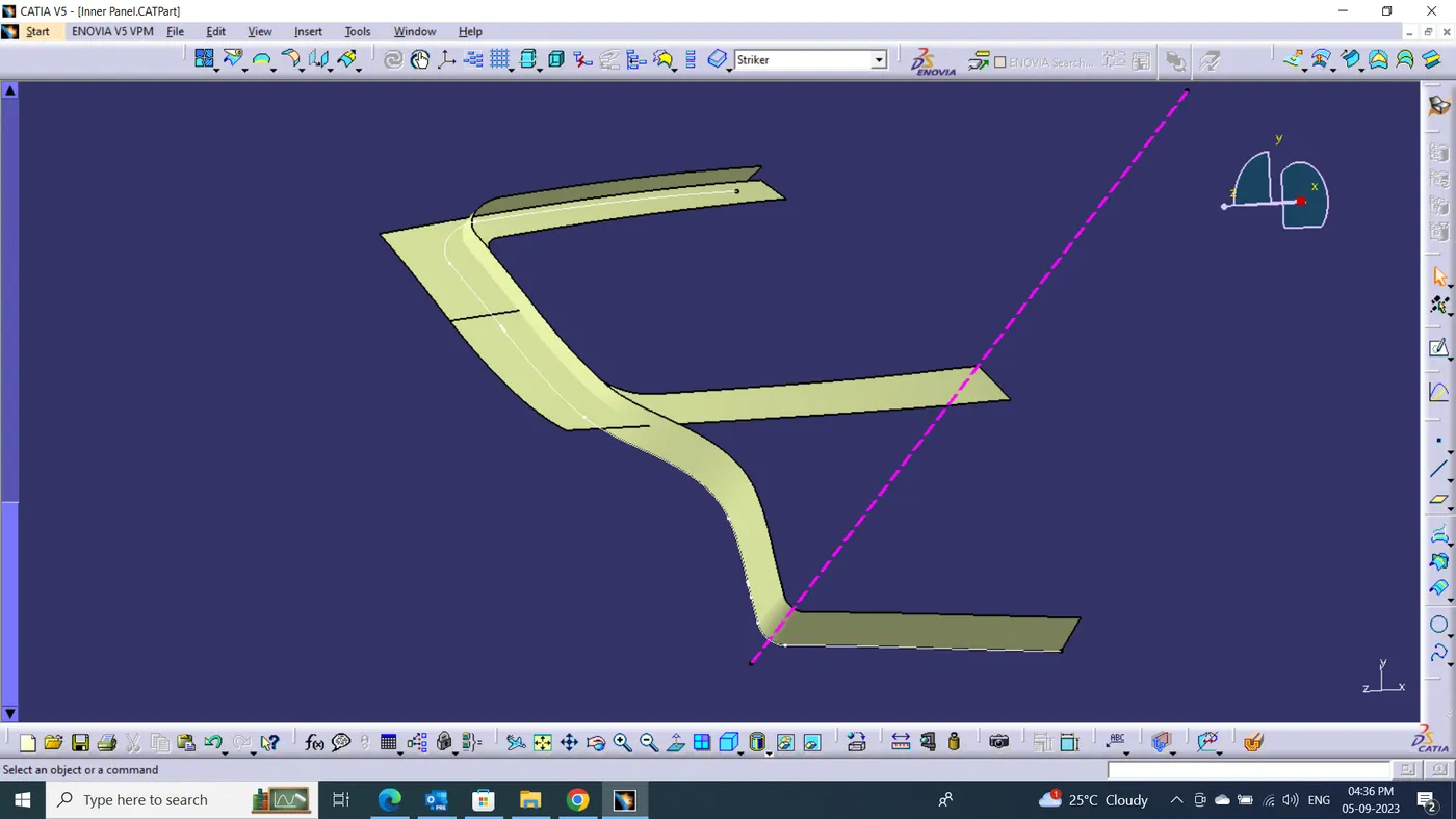
WINDSHIELD AREA
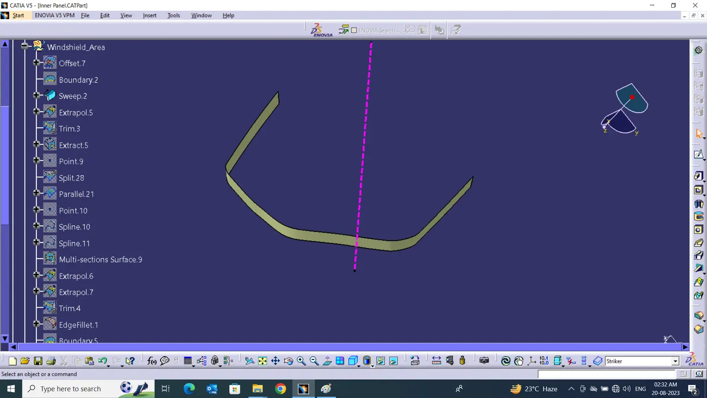
FLANGE WITH NO SHARP EDGES
8. Trim the flange with windshield area use extrapolate the surfaces of both & trim thr surfaces.
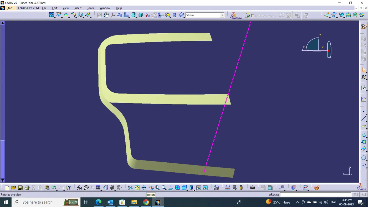
TRIMED FLANGE & WINDSHIED SURFACE
9. To Create surface in lower area of inner panel.
10. Use Multi section surface create a lower surface.
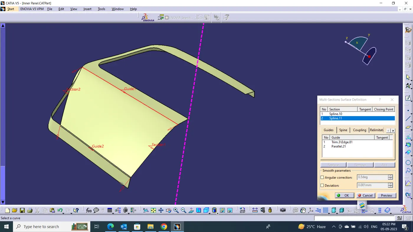
11. use Extrapolate the surface on both edges.
12. Trim surface of both Windshield area & Lower surface of inner panel.
13. Join the developed windshield surface & Sealing - Side Connect surface with trim option.
14. Apply the Edge fillet of all sharp corner edges.
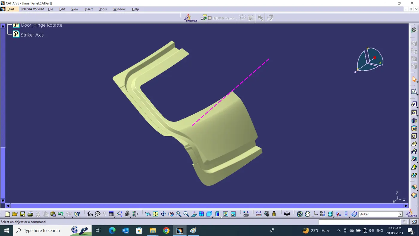
DEVELOPED WINDSHIELD AREA
d) Lancing :
Lancing is the operation of cutting a sheet of metal through part of its length and bending the cut portion. It is used to make tabs, vants, louvers in sheet metal workpiece. Lancing is Absorved the vibratation to inner panel.
To Create lancing On inner panel
- Create Sketch for lancing & project the sketch on Surface.
- Split the surface and select Extract of Edge.
- Use Sweep operation reference of of surface.
- Offset Surface with gap distance of 5mm between Inner panel & upper panel.
- Use trim option & make join the two surfaces of lancing.
- apply edge fillet operation on sharp edges.
- Clear the all Sharp corner on lancing area
- Join the surfaces wirh main inner panel surface.
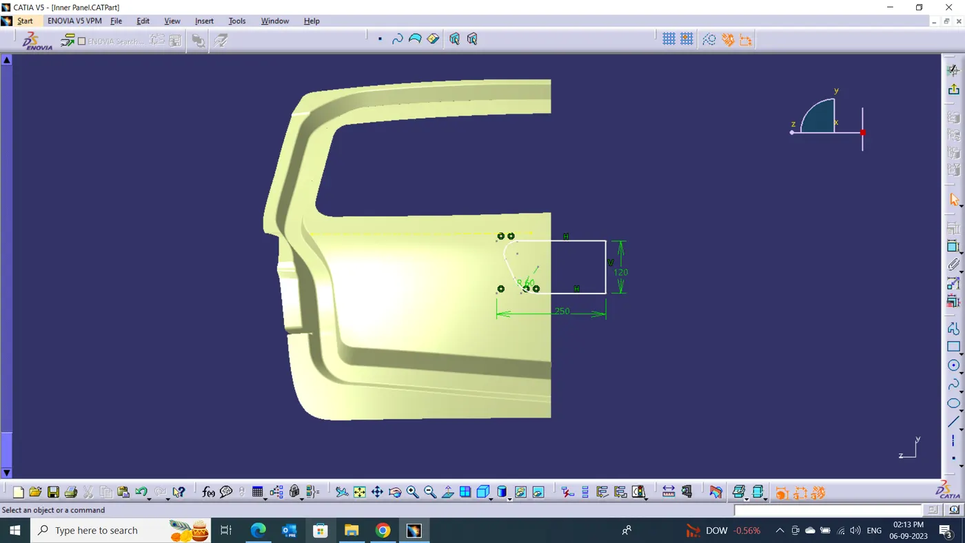
SKETCH
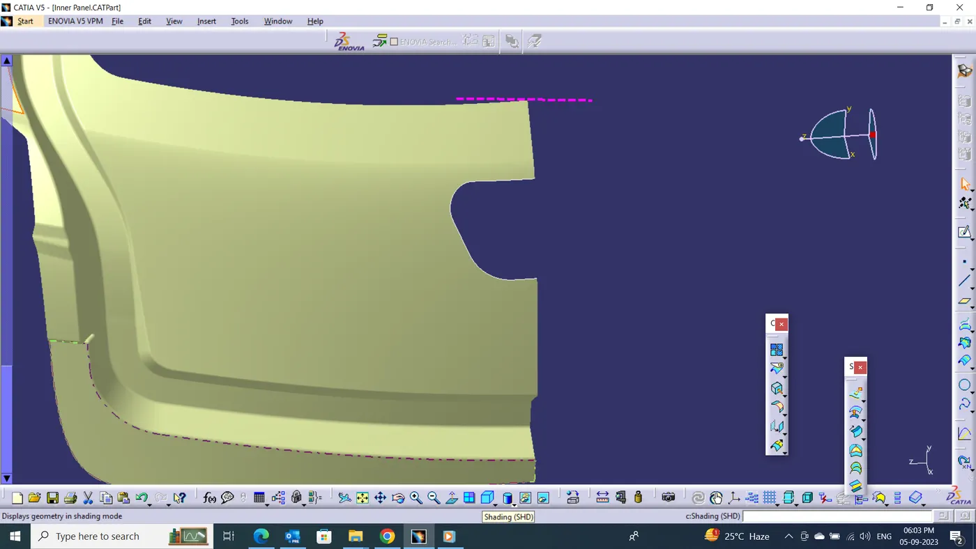
SPLIT AREA
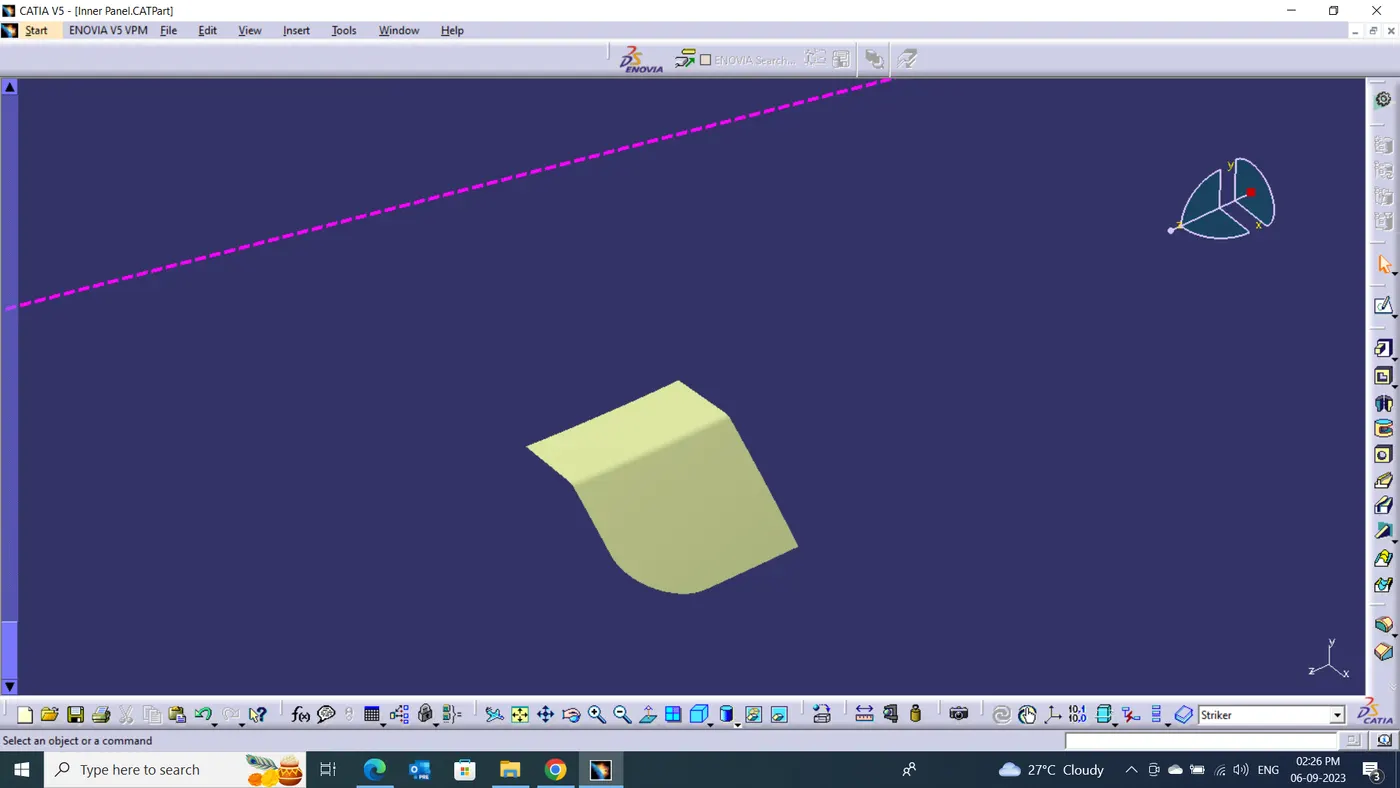
LANCING
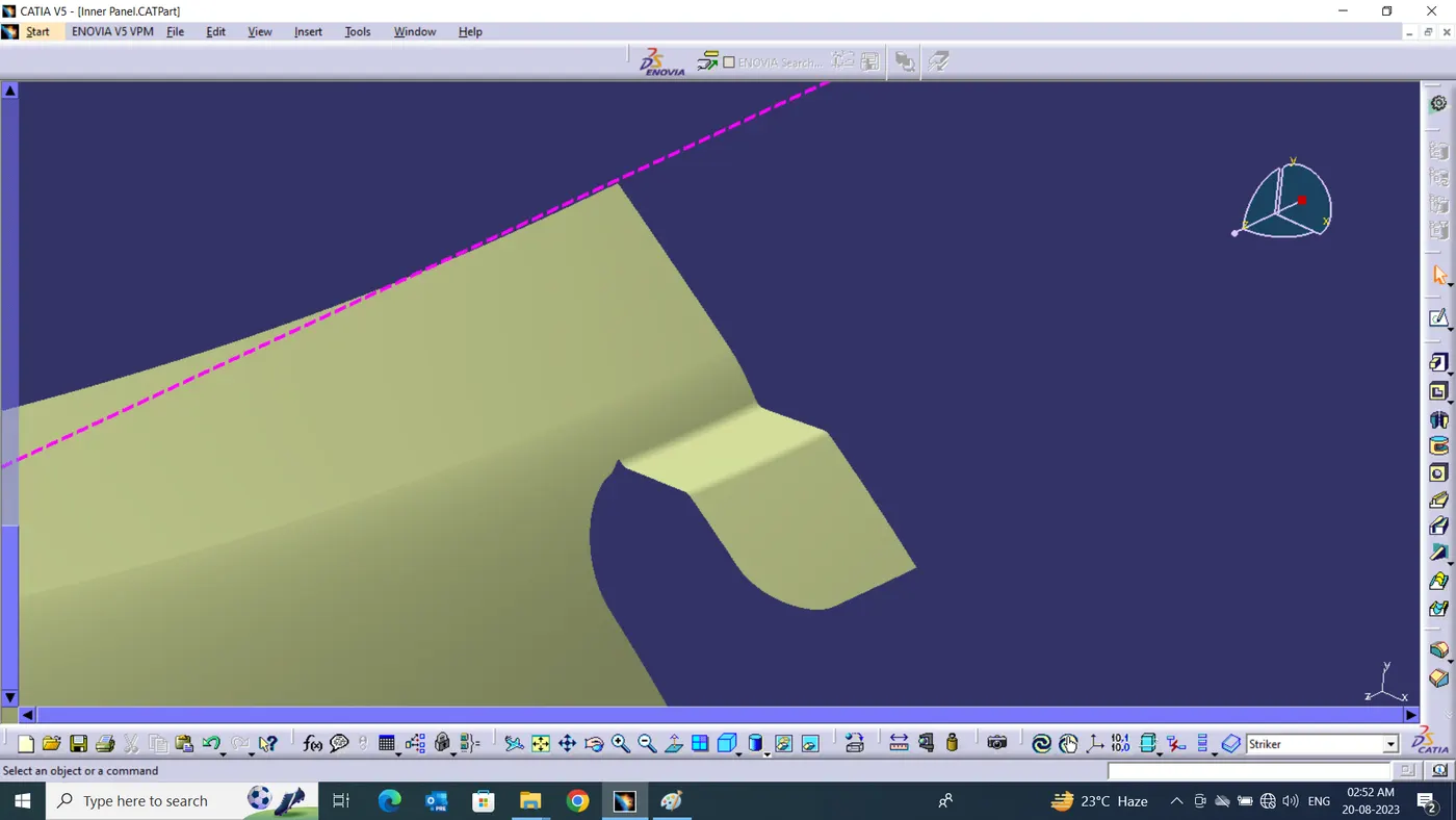
DEVELOPED LANCING
e) Embosing :
Sheet metal embossing is a stamping process for producing raised or sunken designs or relief in sheet metal. This process can be made by means of matched male and female roller dies, or by passing sheet or a strip of metal between rolls of the desired pa
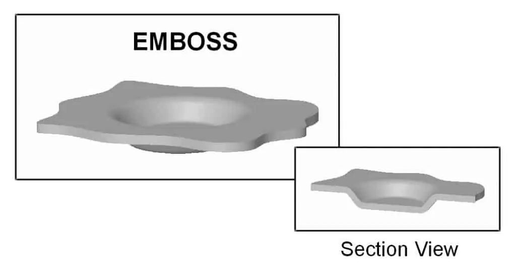
To Create Emboss On inner panel
- Create Sketch for Emboss & project the sketch on Surface.
- Split the surface and select Extract of Edge.
- Use Sweep operation reference of of surface.
- Offset Surface with distance of 5mm.
- Use trim option & make join the two surfaces of Emboss.
- apply edge fillet operation on sharp edges.
- Join the surfaces wirh main inner panel surface.
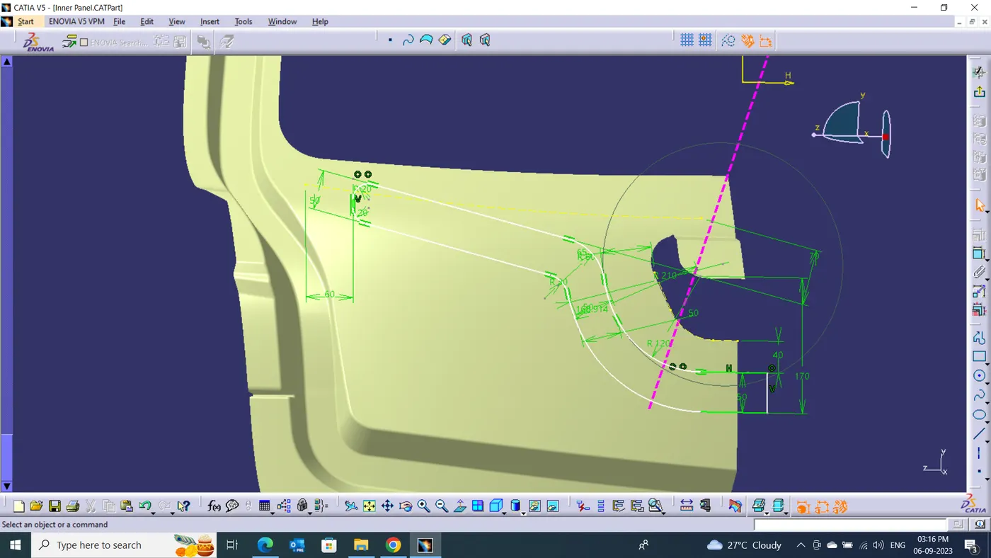
SKETCH
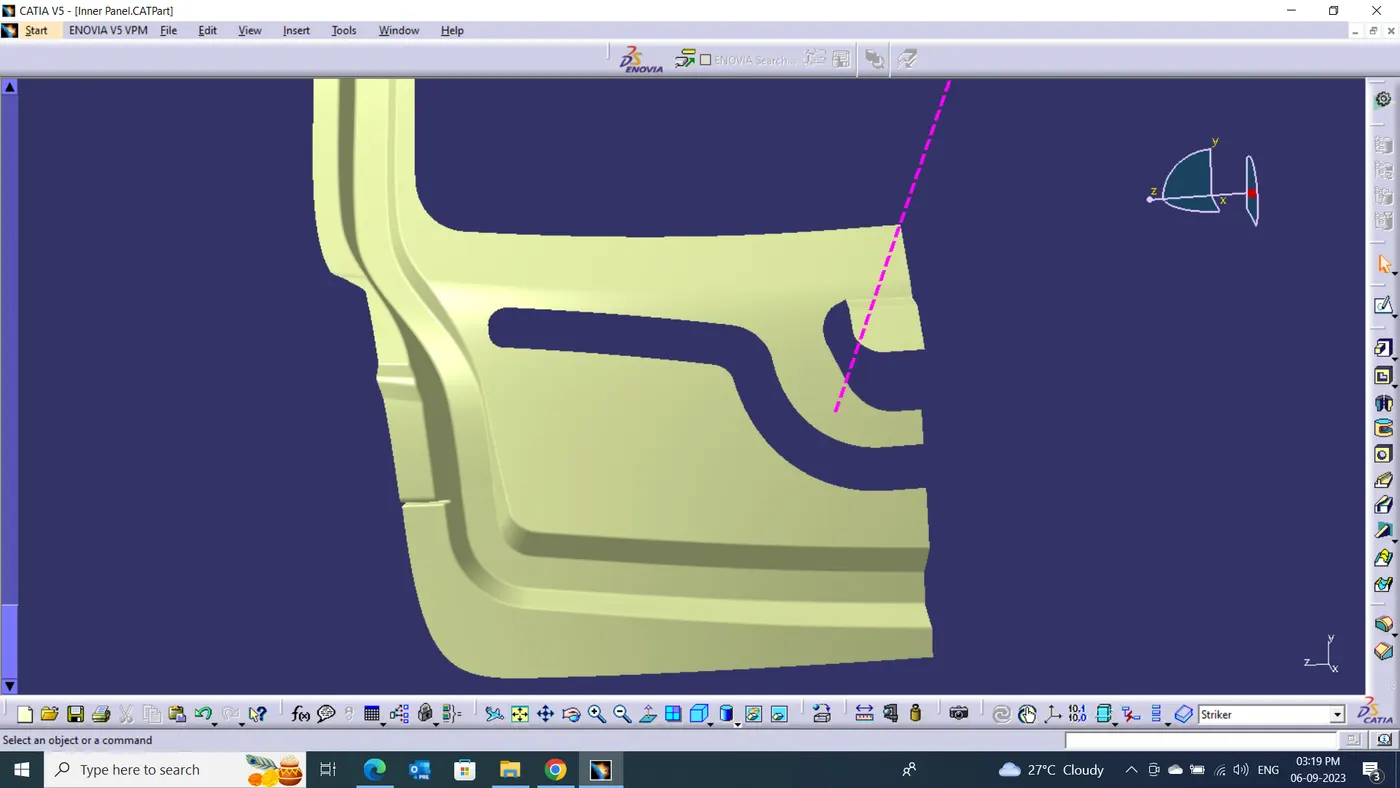
SPLIT SURFACE
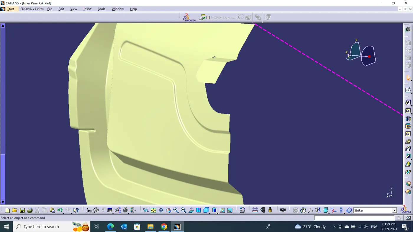
EMBOSS
8. Create a sketch for split surface.
9. Project the Sketch on surface to split the surface.
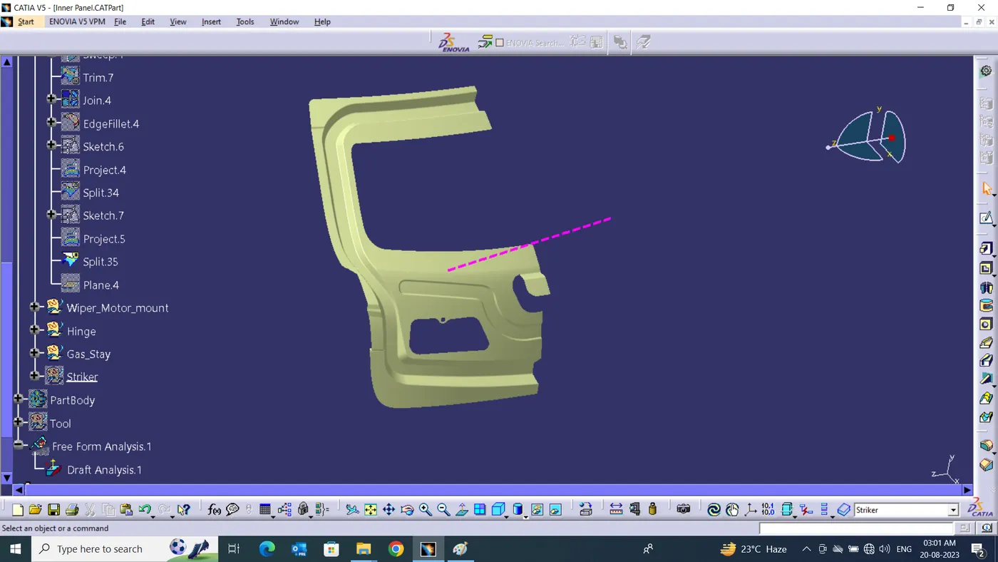
f) Wiper Motor Mount :
Wiper motor mount area is guide for placing of Wiper on back door.
- Create Sketch & project the sketch on Surface.
- Split the surface and select Extract of Edge.
- Use Sweep operation reference of Tooling Axis.
- Offset Surface with distance of 5mm.
- Use trim option & make join the two surfaces of Emboss.
- apply edge fillet operation on sharp edges.
- Join the surfaces wirh main inner panel surface.
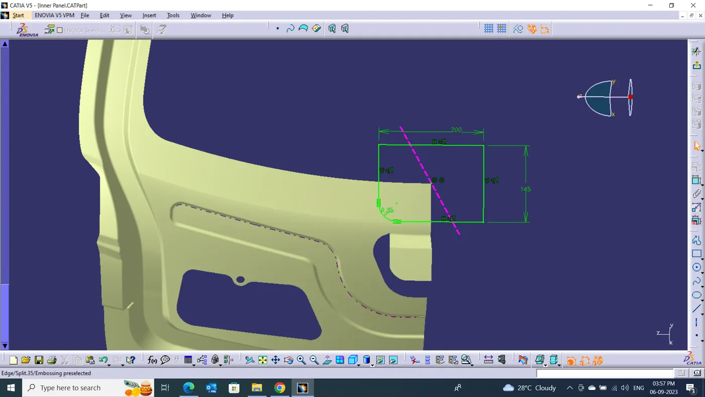
SKETCH
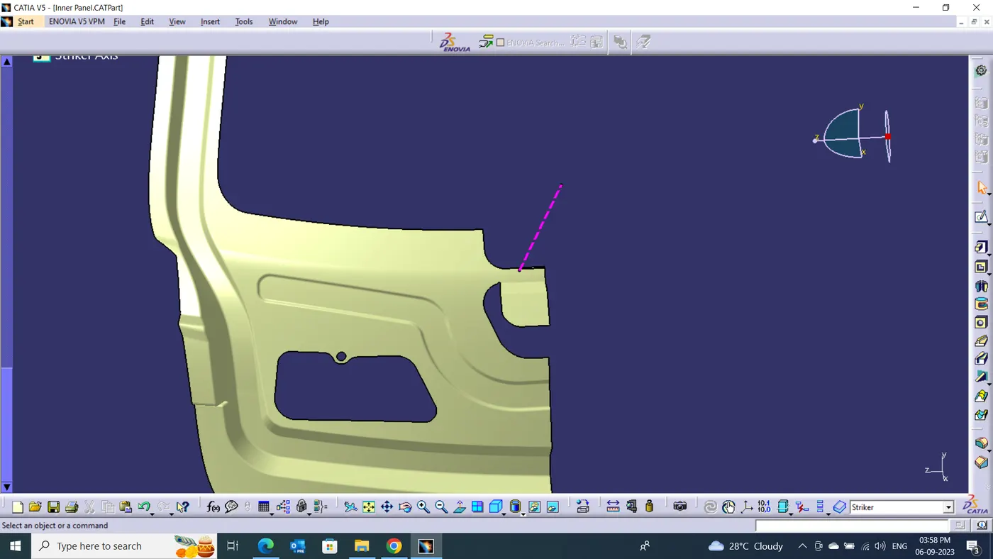
SPLIT SURFACE
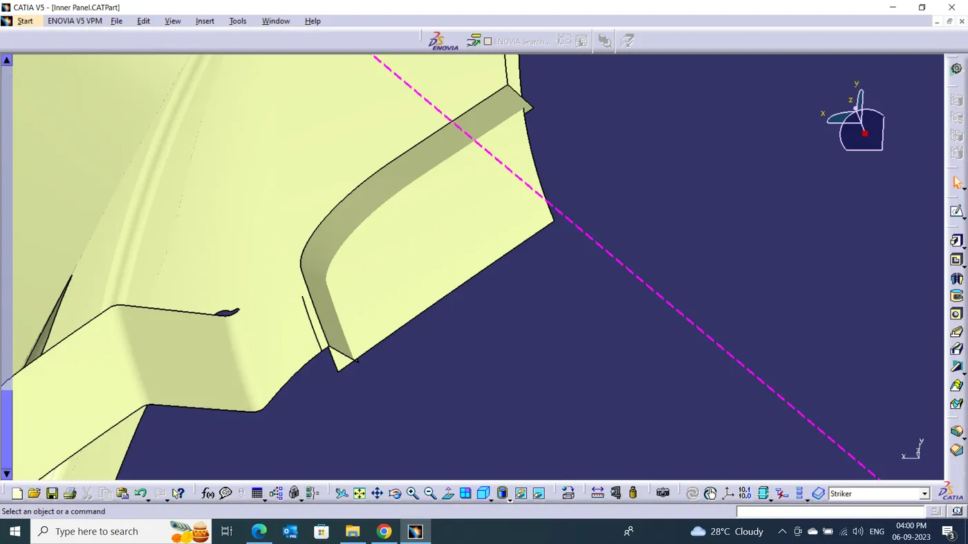
SWEEP & OFFSET SURFACE
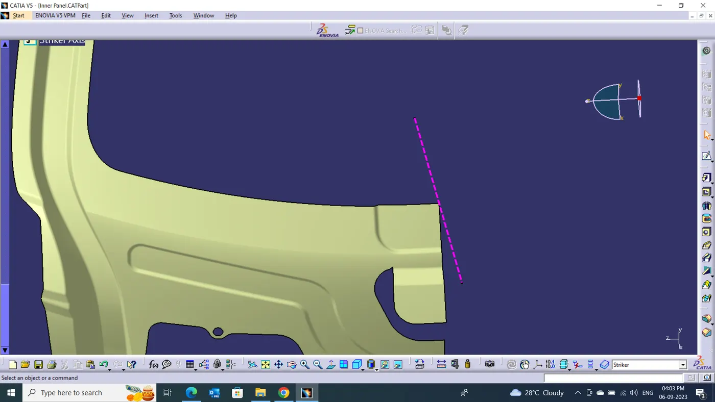
WIPER MOTOR MOUNT
8. Create Hole on the wiper motor mount area.
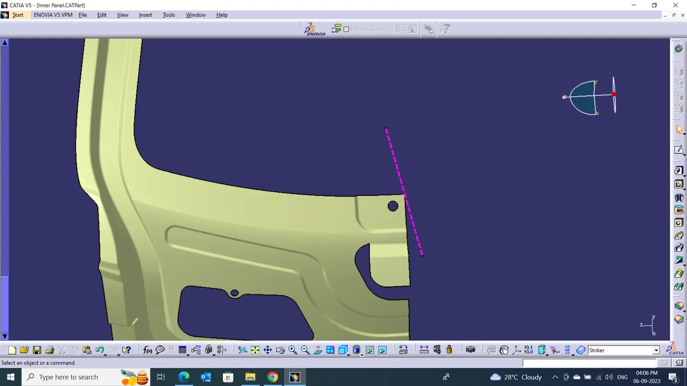
WIPER MOTOR MOUNT WITH HOLE
9. Create Emboss on Wiper motor mount area.
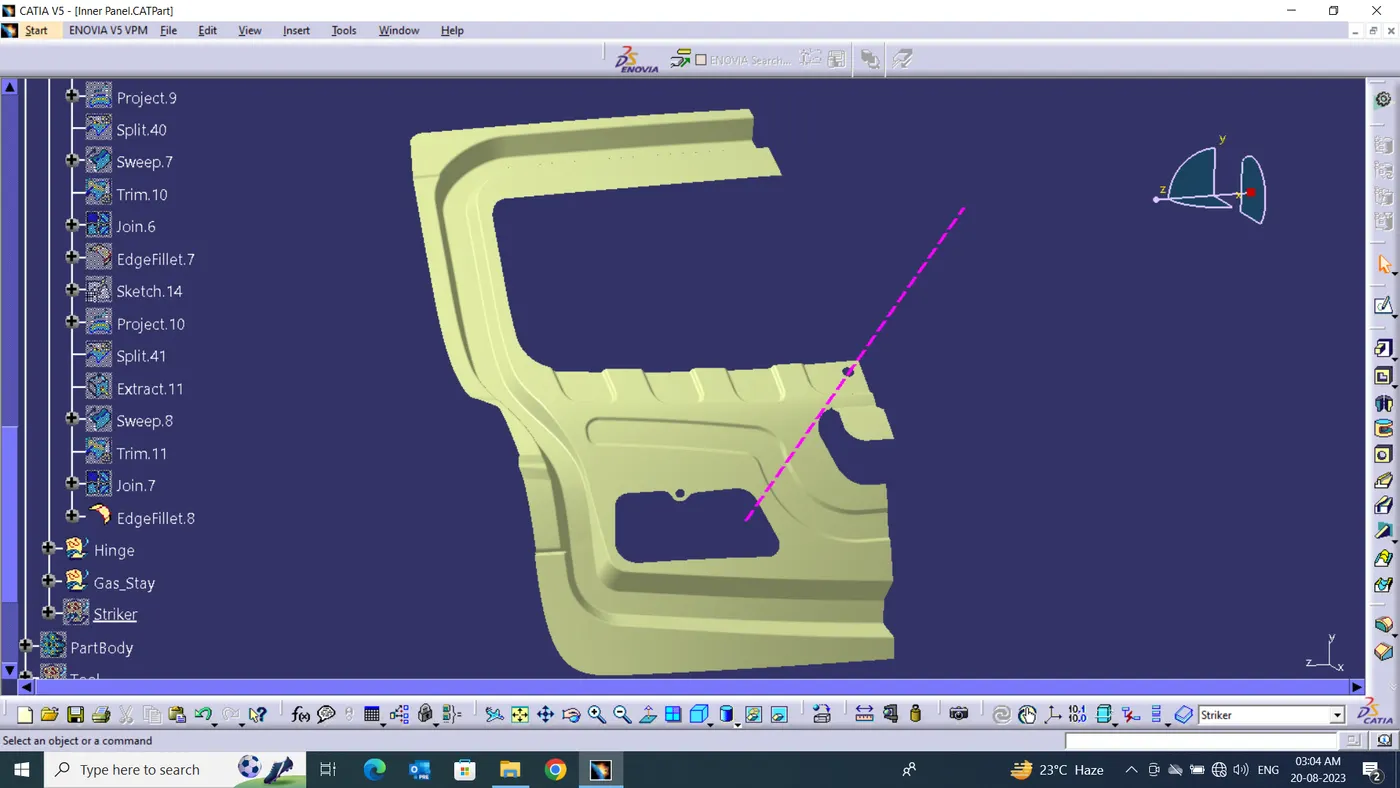
DEVELOPED WIPER MOTOR MOUNTAINING AREA
g) Hinge :
A hinge is a type of joint that attaches two things together while allowing for limited movement. A door hinge fastens the door to the wall and lets the door swing open. A hinge is a joint that holds two pieces of something together while allowing one piece to move in a swinging motion.
To Create Hinge On inner panel
- Create Sketch of straight line & create guide line in poin to point method.
- Create Surface use Sweep-Line Profile as sketch guide curve as Draft direction.
- create surfces with sweep use Tooling axis at an angle.
- Join the surface.
- Trim Surfaces of Join Surface & inner panel surface.
- Apply edge fillet operation on sharp edges.
- Select plane 3 points method and create sketch of Circle.
- Extrude the circle & Split the hinge surface.
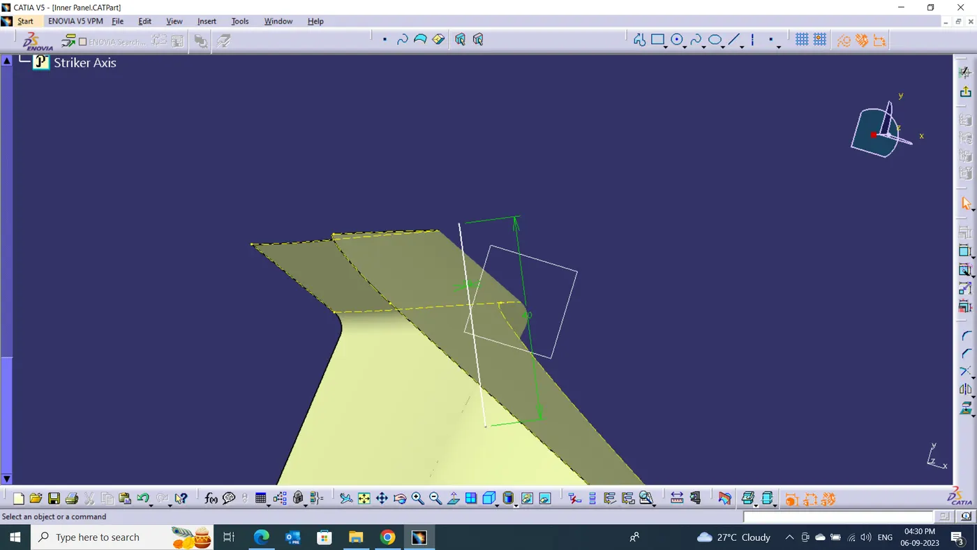
SKETCH
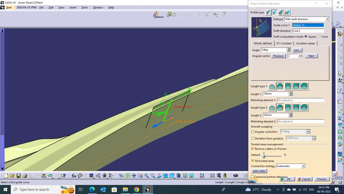
SWEEP SURFACE
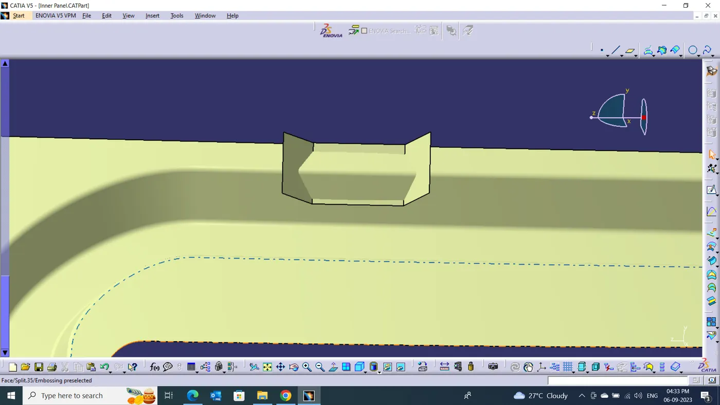
SWEEP SURFACE
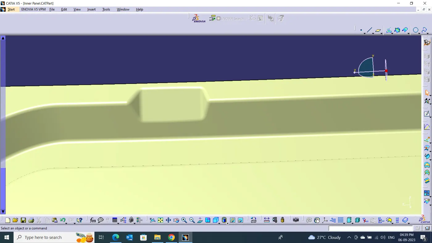
HINGE SURFACE
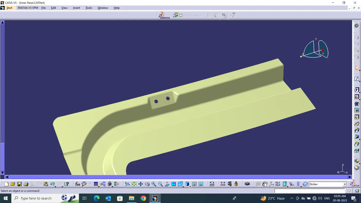
HINGE SURFACE WITH HOLE
h) Gas Stay :
Gas stay in a tail gate is used hold open and close the tail gate. It eliminates man power by holding the back door open in position. one end of the gas stay is fixed on the door and other on the body side.
To Create Hinge On inner panel
- Extract the surface & offset surface of extrct surface.
- Select plane 3 points method and create sketch.
- Project sketch on Offset surface & split the surface.
- Create Surface use Sweep-Line Profile as sketch guide curve as Draft direction.
- Join the surface.
- Trim Surfaces of Join Surface & inner panel surface.
- Apply edge fillet operation on sharp edges.
- Select plane 3 points method and create sketch of Circle.
- Extrude the circle & Split the hinge surface.
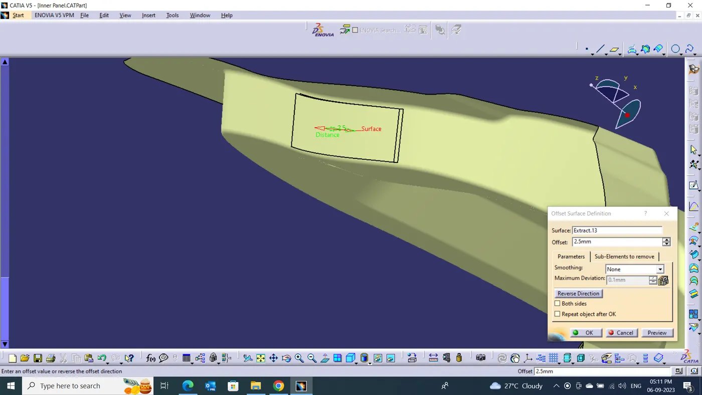
OFFSET SURFACES
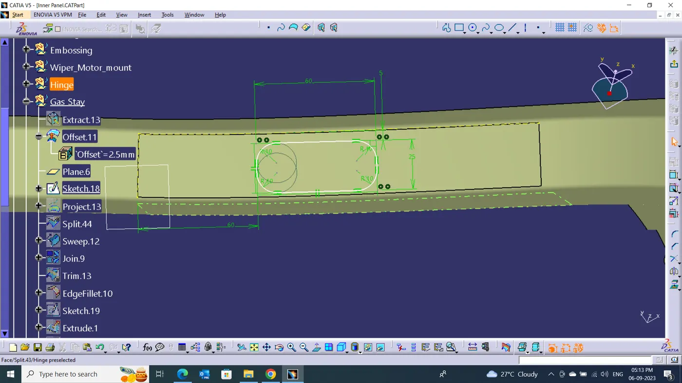
SKETCH
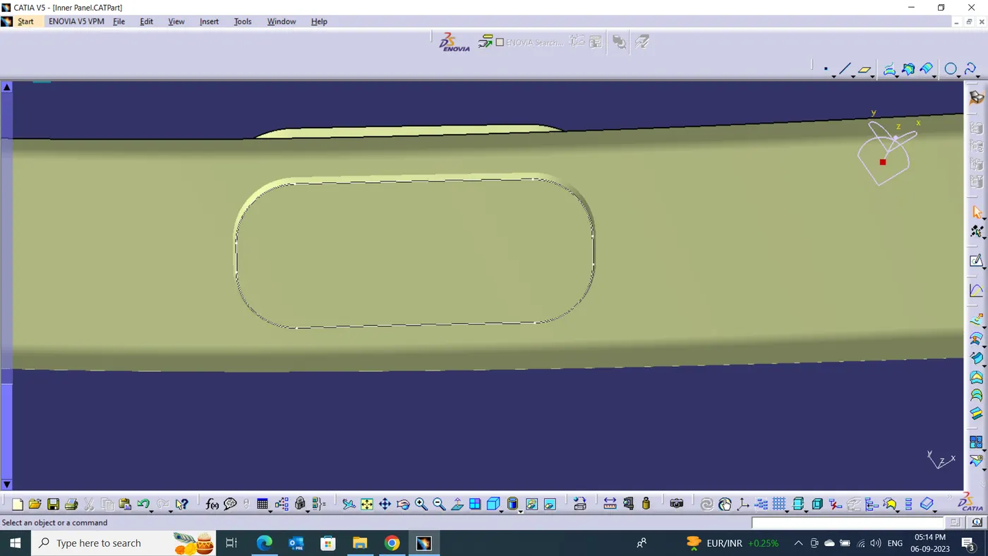
PROJECT CURVE & SPLIT SURFACE
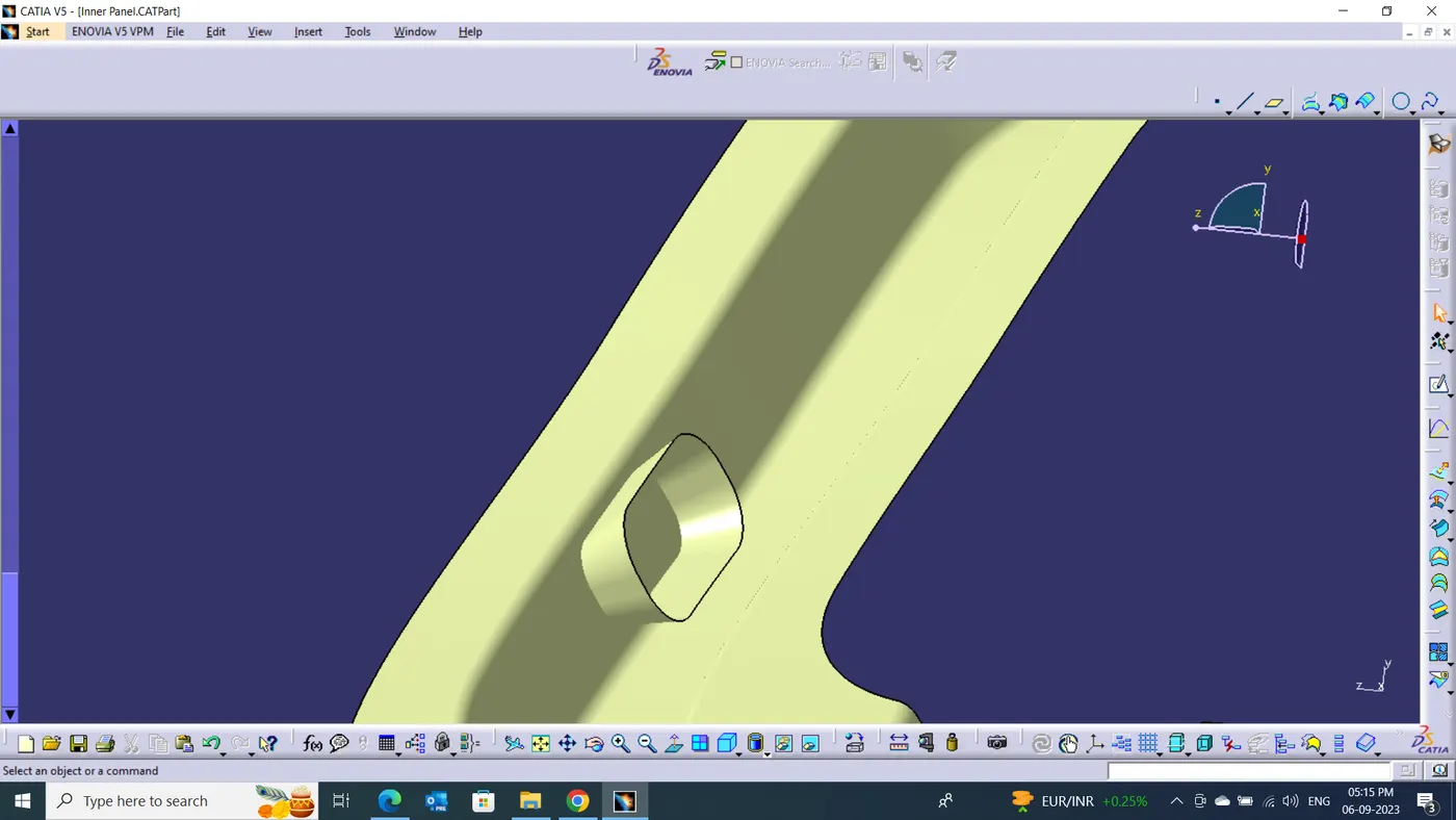
SWEEP SURFACE
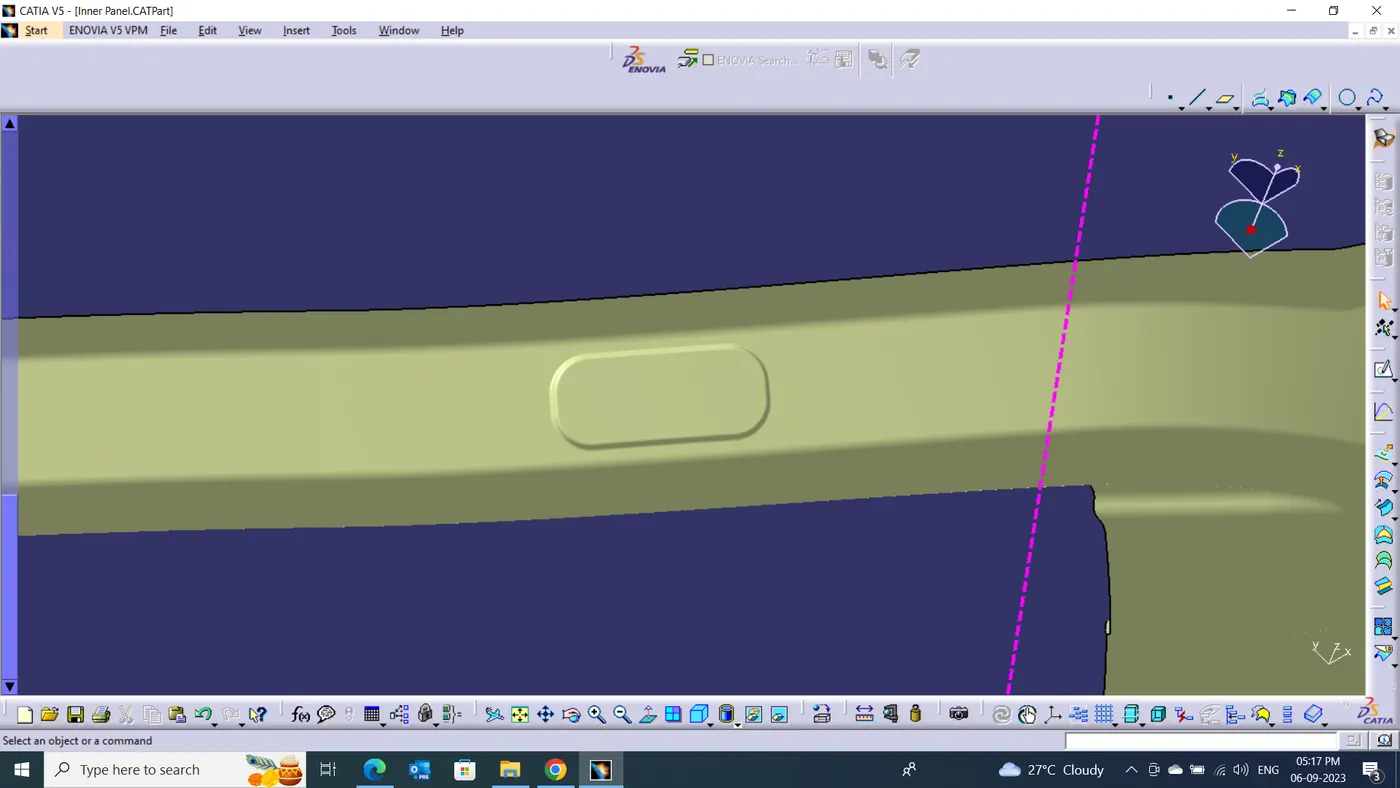
GAS STAY EMBOSS
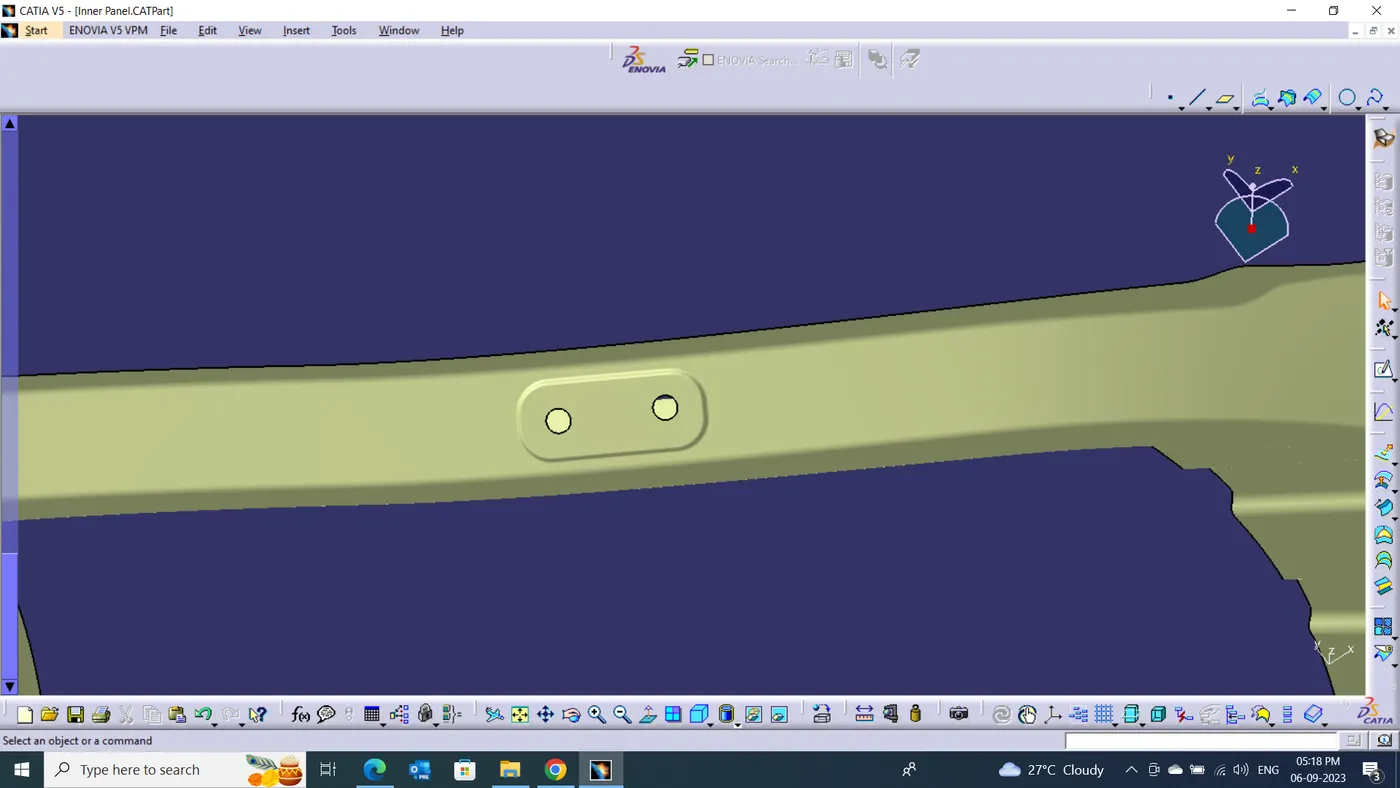
GAS STAY EMBOSS WITH HOLES
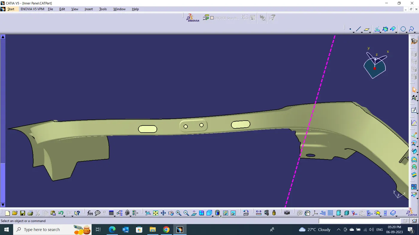
DEVELOPED GAS STAY AREA
i) Striker :
Latch and striker is responsible for locking of the back door. Stress will be developed as we frequently open and close the door so adding a reinforcement will make it stronger.
a) To Create the Latch & striker positon.
- Mirror the of developed skin surface.
- Join Both surface with no gap & Clear shrp edges on the Joined surfaces.
- create points on circle center on hinge holes.
- create hinge axis on from both hinge circle center points.
- select plane on curve perpendicular in mid point of hinge axis.
- create a sketch of circle with center of hinge axis which is door open & close with respect to hinge.
- Create tangent line to circle axis to latch & striker.
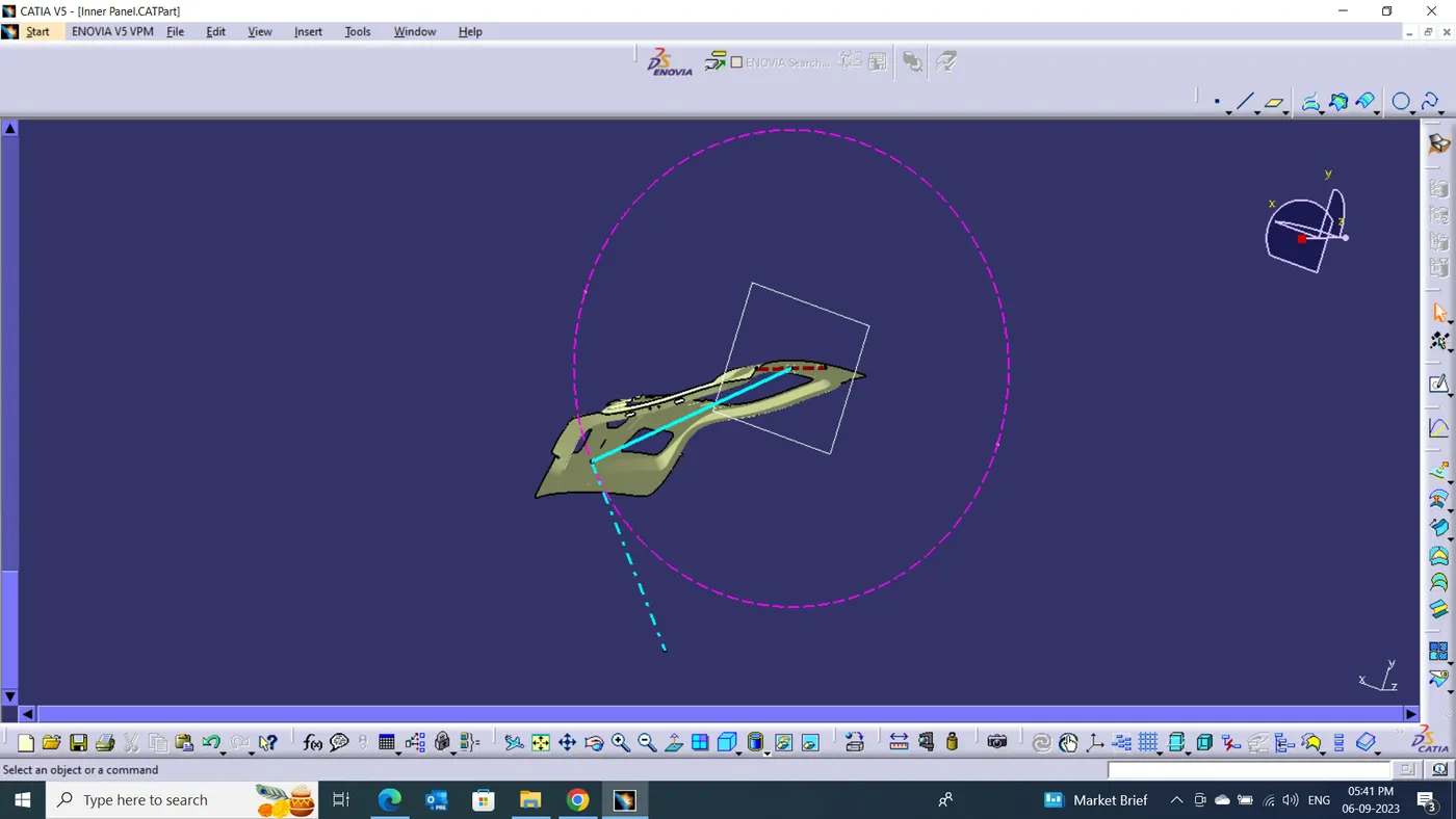
b) To Create striker in Inner panel.
- Create Sketch of straight line & create guide line in poin to point method.
- Create Surface use Sweep-Line Profile as sketch guide curve as Draft direction.
- create surfces with sweep use Tooling axis at an angle.
- Join the surface.
- Trim Surfaces of Join Surface & inner panel surface.
- Apply edge fillet operation on sharp edges.
- Select plane 3 points method and create sketch of Circle.
- Extrude the circle & Split the hinge surface.
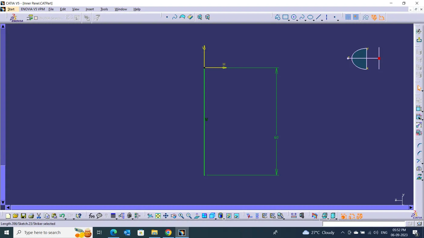
STRIKER SKETCH
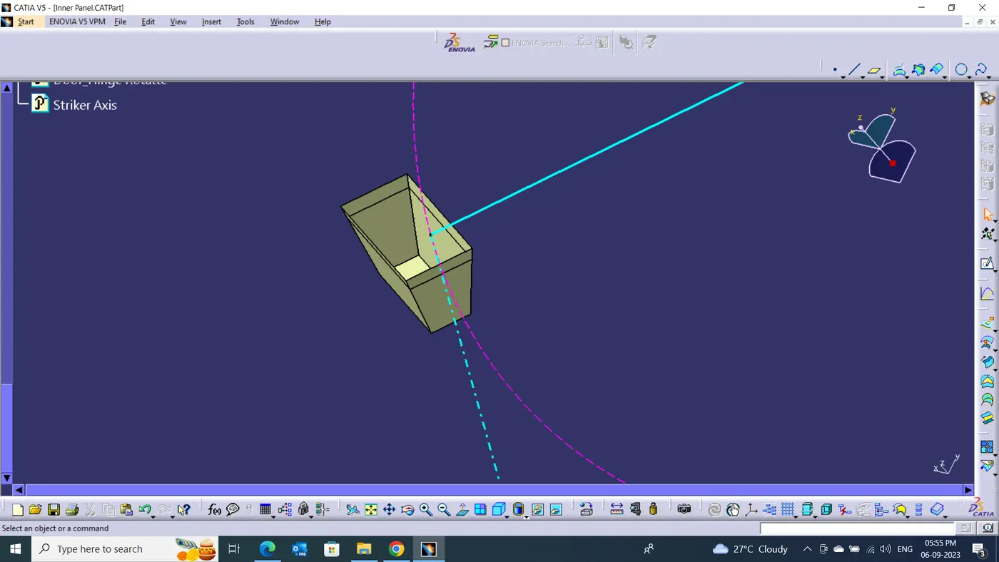
SWEEP SURFACES
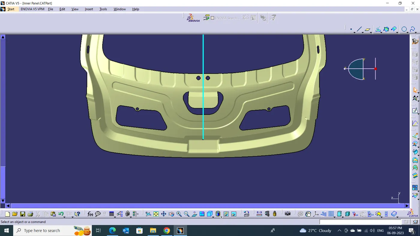
STRIKE EMBOSS
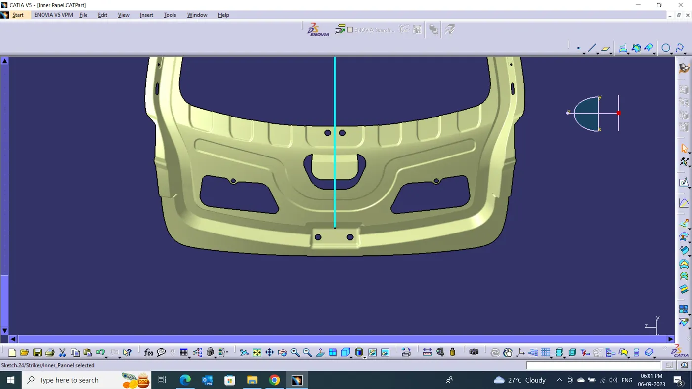
STRIKE EMBOSS WITH HOLES
CONVERT PART FROM SURFACE :
- Thick the surface 0.75mm to the outer panel side.
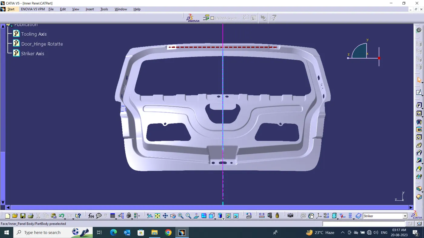
THICKEND INNER PANEL
NOTE : 1. Check any Sharp Edges on Surface.
2. Check Proper Draft angel.
3. HEMMING :
Hemming is a common metal working process mainly carried out to reinforce an edge, hide burrs or just improve the overall appearance of sheet metal parts. When hemming is carried out in a way that a joint between two sheet metal parts is created, it is called seaming but more on that later.
WHAT IS HEMMING :
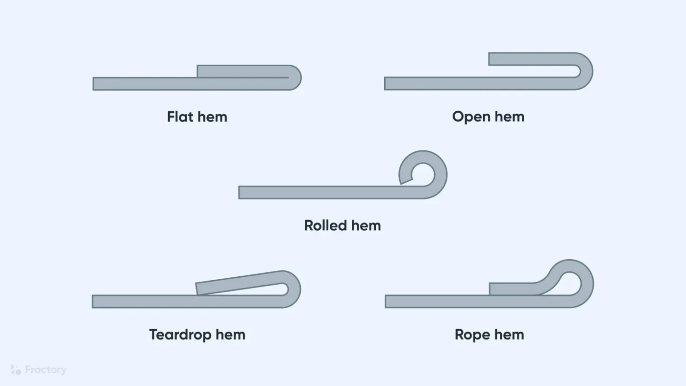
Hemming in sheet metal operations refers to the bending of sheet metal edge onto itself. It is very similar to edge stitching in clothes. Similar to how an edge stitch strengthens the edge and makes it more durable, a hem imparts strength to the metal edge and improves its appearance. The edge of one part may also be folded onto another part to create a joint.
Hemming is usually done in two stages. The first stage creates an acute bend using acute tooling (V die) followed by a flattening of the return flange using a flattening die.
A complete list of hemming benefits on a sheet metal product is as follows:
-
Hems strengthen the sheet metal edge
-
They improve the surface appearance and surface quality
-
They hide defects such as rough edges and burrs
-
They can connect parts
-
They make the edges safer to handle
TYPES OF HEMMING
 RELIEF CORNER :
Hemming relife is defined as reduce the stress corners edges and neglete the over laping of material.
DESIGN PROCEDURE FOR HEMMING.
Upper Panel Hem:
- Extrapolate the repaired Class A surface 2mm to 5mm.
- Remove Sharp Corners of surface.
- Offset the surface 2.65mm to inner panel side.
- Create Paralle curve line from boundary of surface with 10 x Thickness of sheet.
- Split the surfaces with parallel curve.
- Create Corner relief for remove stress of material at corer.
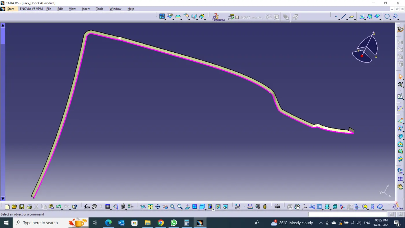
SPLIT SURFACE WITH PARALLEL CURVE
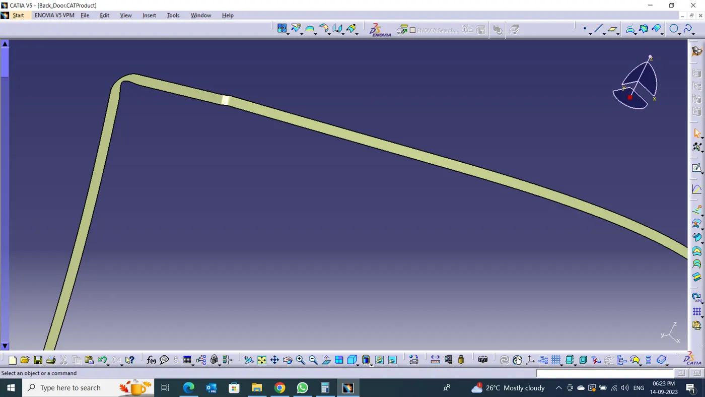
RELIEF CORNER
Connect surface .
To Create a Rolled connect surface between two surfaces.
- Create Sweep Surface in lower surfce hemming pependicular to rerence surface 0.5mm one side & 2.5mm other side.
- Verify the sharp edges on surface.
- Remove sharp edges. use the parallel curve on both side of sharp edge & split on both sides.
- Fill the gaps surface use multisection surface with respect to tangenet surfaces.
- Apply the join surface of all no connexity.
- join the surface use Tri-Tangent shape fillet.
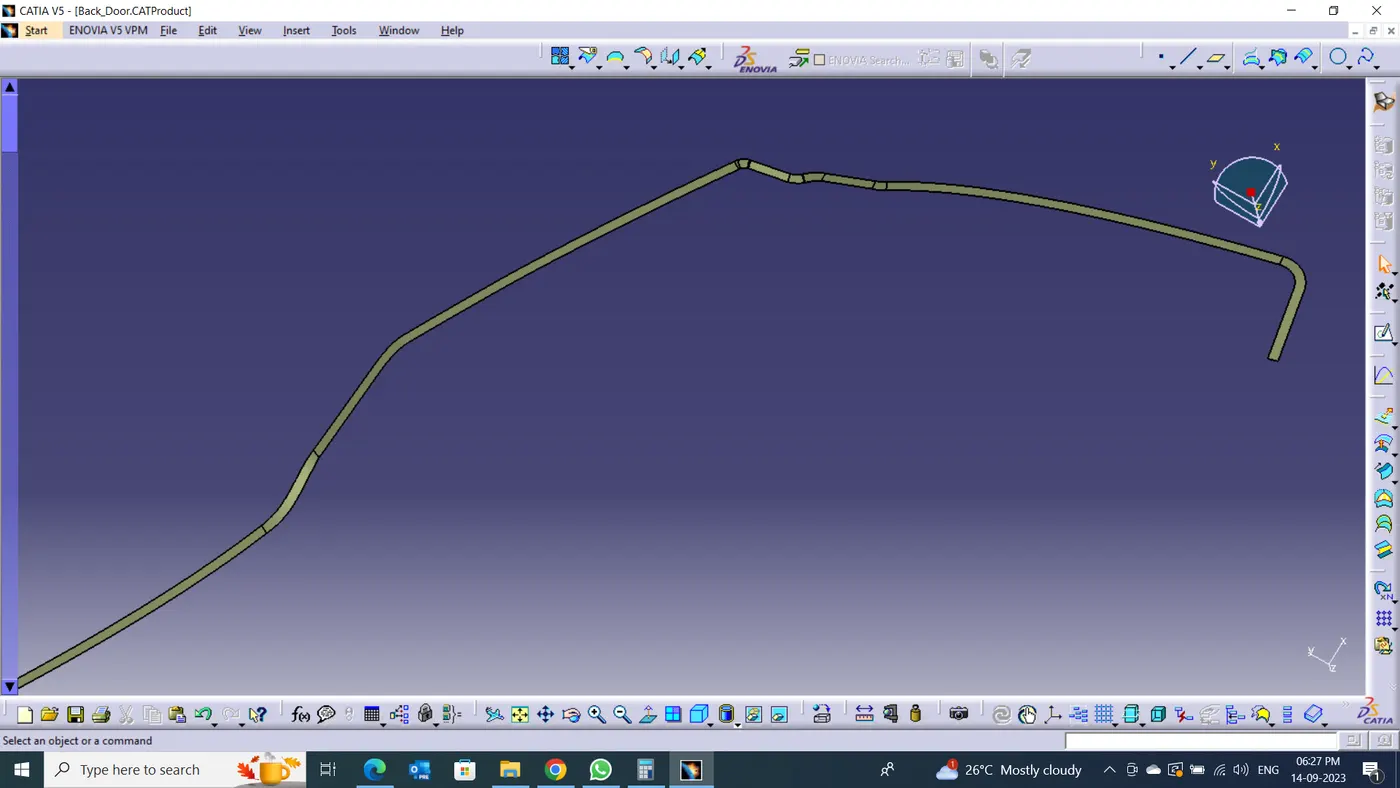
SURFACE WITH SHARP EDGES
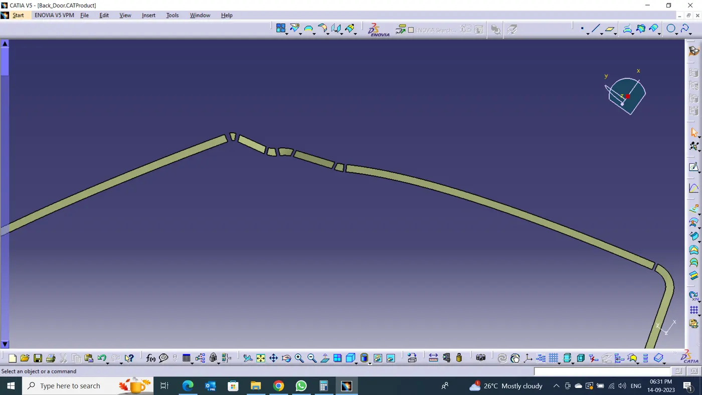
SHARP EGGES REMOVED SPLIT SURFACES
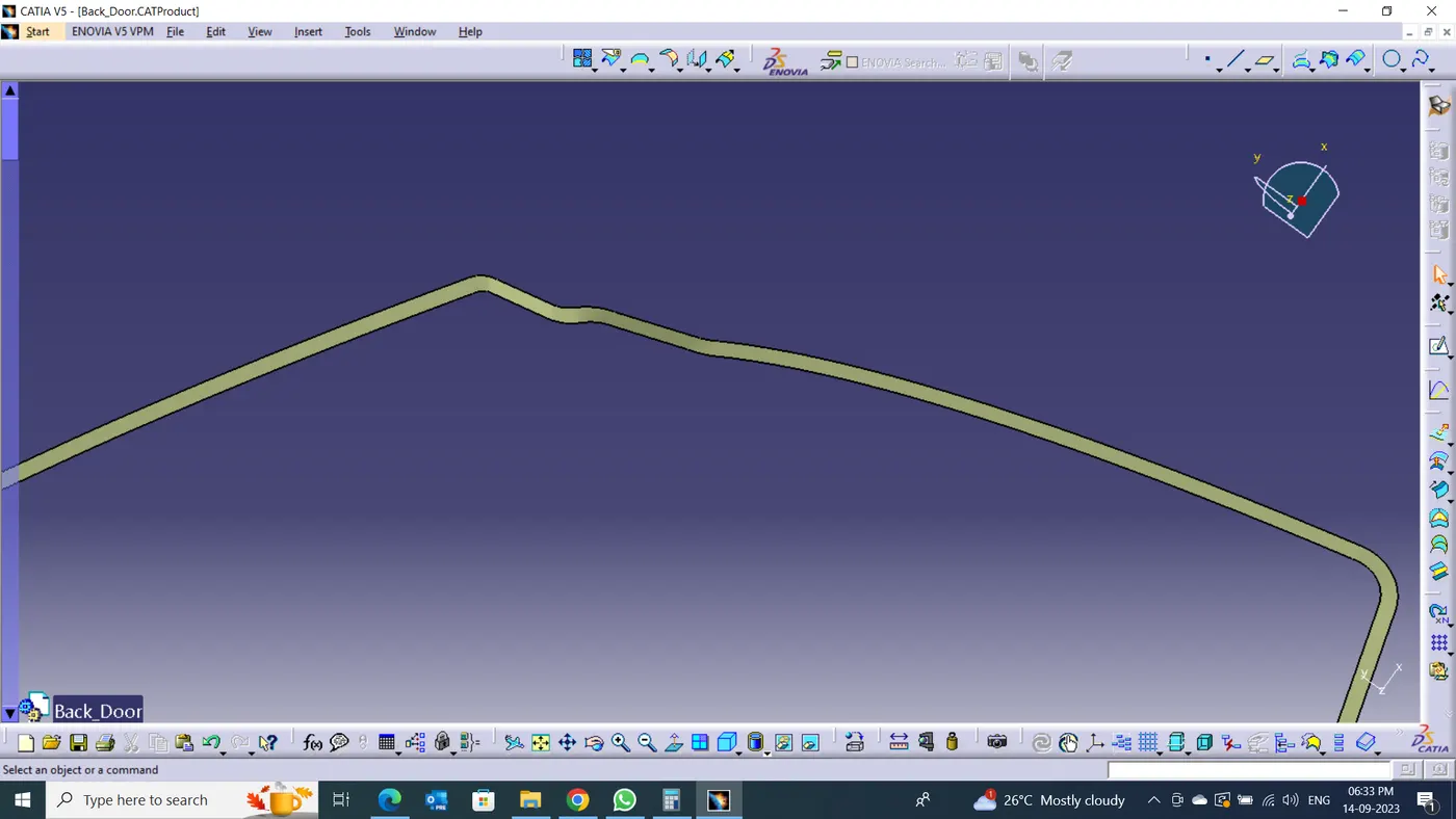
SURFACE WITH NO SHARP EDGES
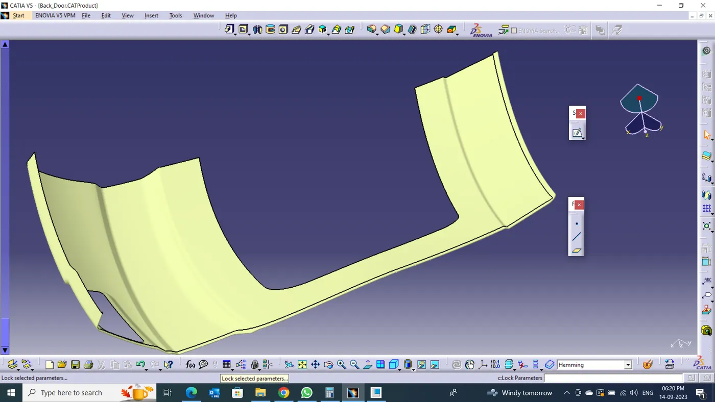
DEVELOPED SURFACE
MIRROR SURFACE :
Mirror the surface oppsite side.
- Give extra length of surface Uuse extrapolate.
- Split surface with XY Plane.
- Symmetry surface with XY plane
- join the surface.
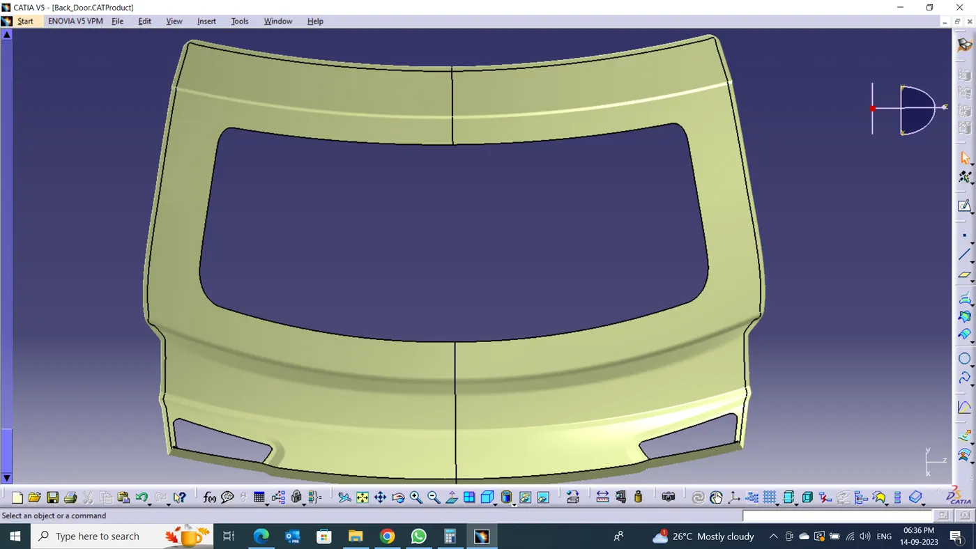
SYMMETRY SURFACE
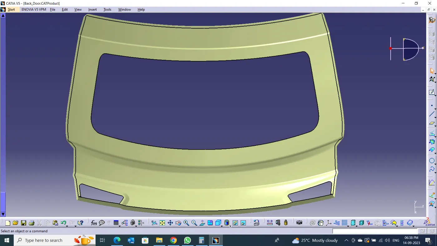
JOINED SURFACE
CONVERT PART FROM SURFACE :
- Thick the surface 0.75mm to the outer panel side.
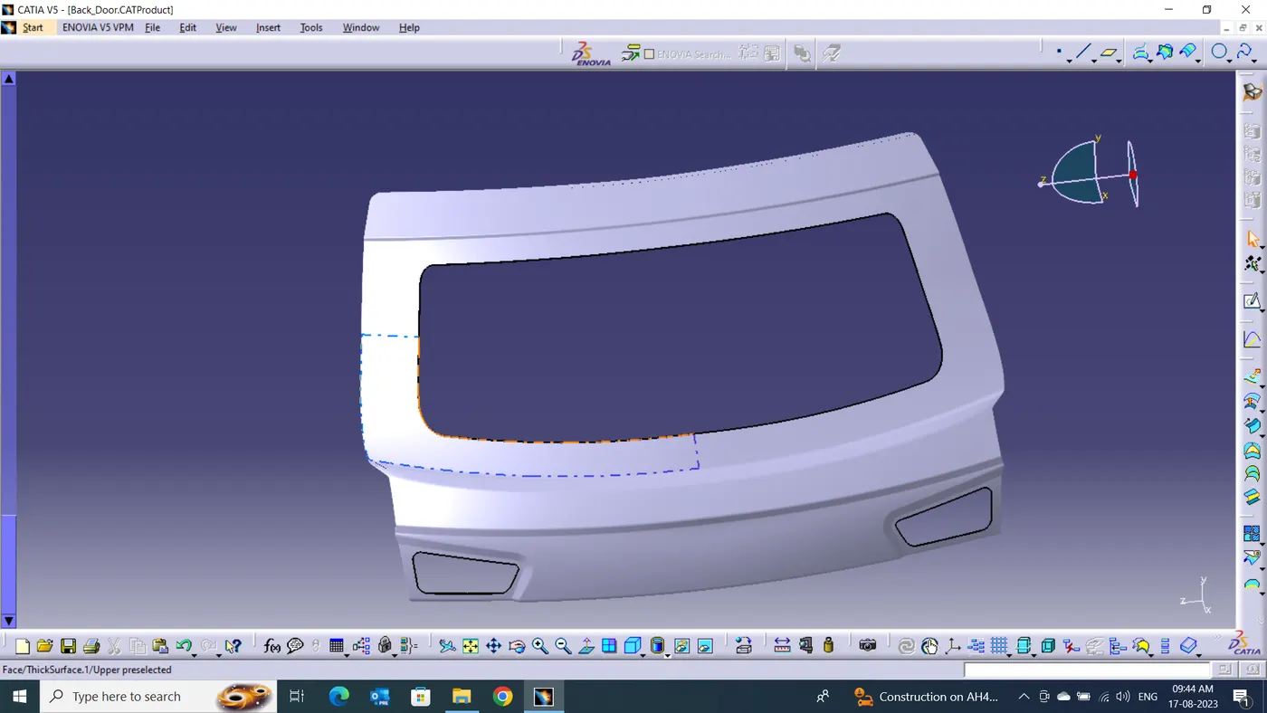
THICKEND UPPER PANEL(OUTER PANEL)
LOWER PANEL :
- Extrapolate the repaired Class A surface 2mm to 5mm.
- Remove Sharp Corners of surface.
- Offset the surface 2.65mm to inner panel side.
- Create Paralle curve line from boundary of surface with 10 x Thickness of sheet.
- Split the surfaces with parallel curve.
- Create Corner relief for remove stress of material at corer.
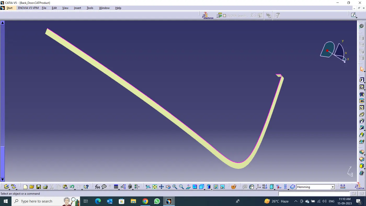
SPLIT SURFACE WITH PARALLEL CURVE
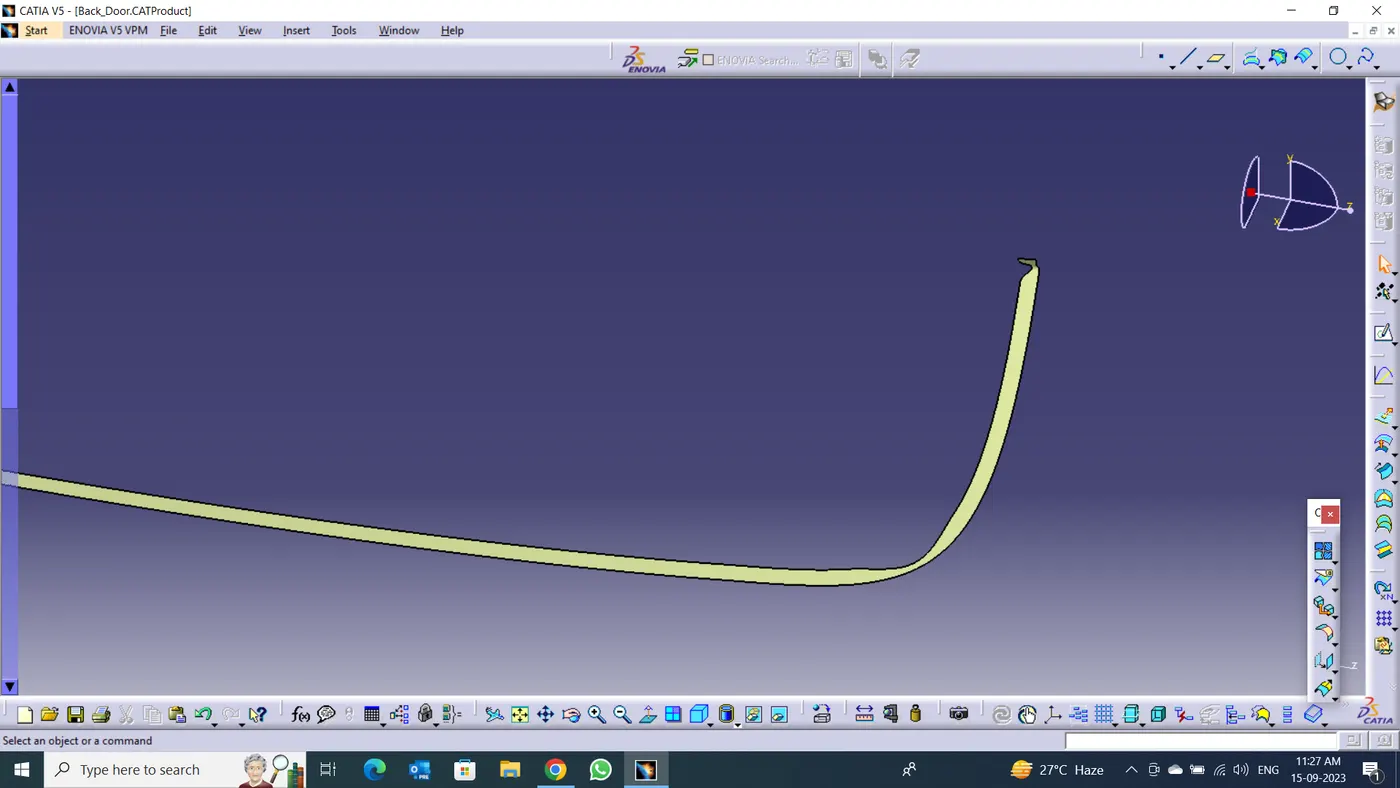
RELIEF CORNER
Connect surface .
To Create a Rolled connect surface between two surfaces.
- Create Sweep Surface in lower surfce hemming pependicular to rerence surface 0.5mm one side & 2.5mm other side.
- Verify the sharp edges on surface.
- Remove sharp edges. use the parallel curve on both side of sharp edge & split on both sides.
- Fill the gaps surface use multisection surface with respect to tangenet surfaces.
- Apply the join surface of all no connexity.
- join the surface use Tri-Tangent shape fillet.
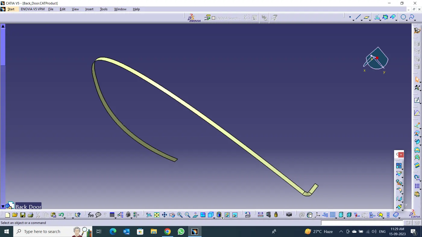
SURFACE WITH SHARP EDGES
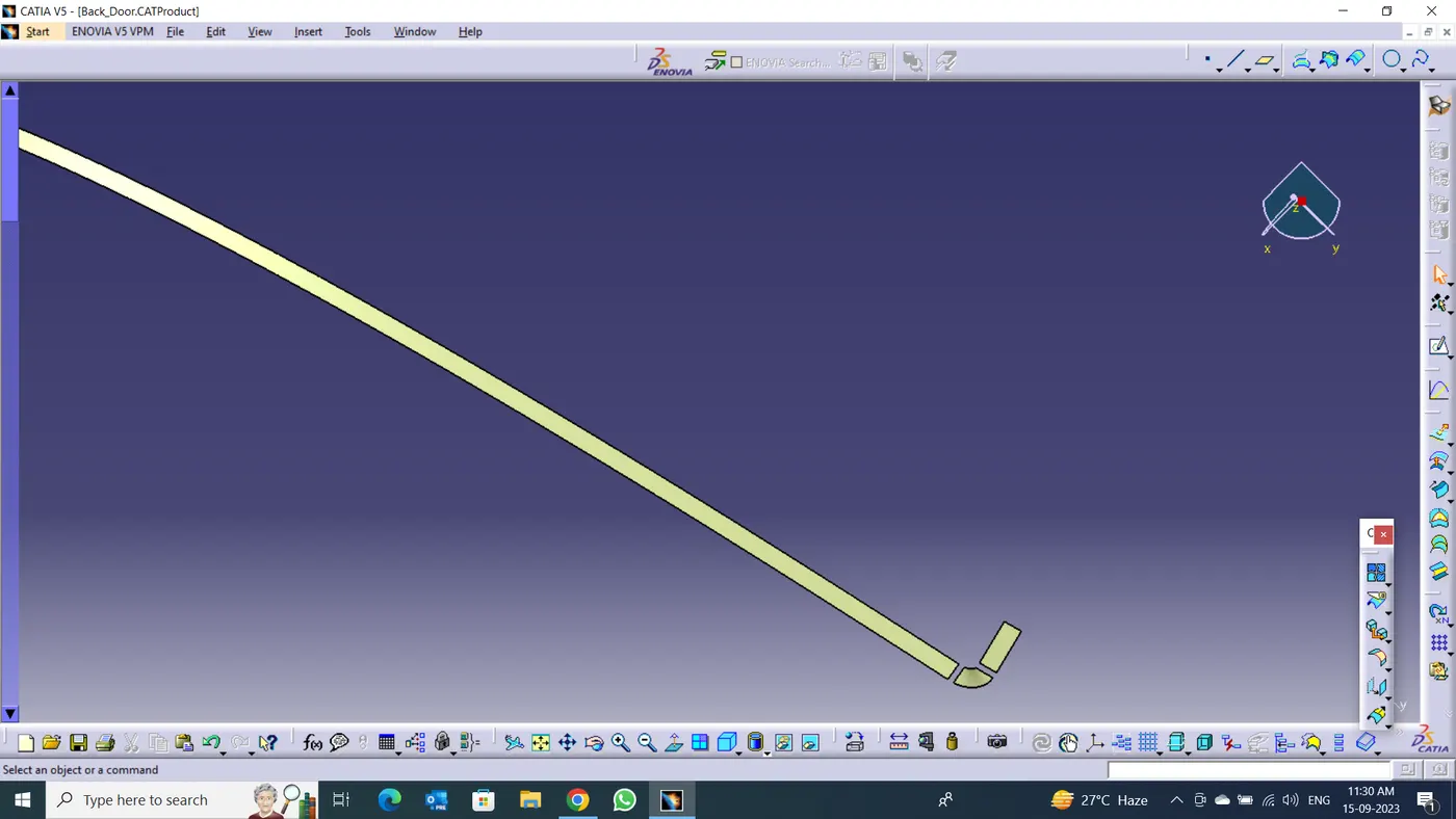
SHARP EGGES REMOVED SPLIT SURFACES
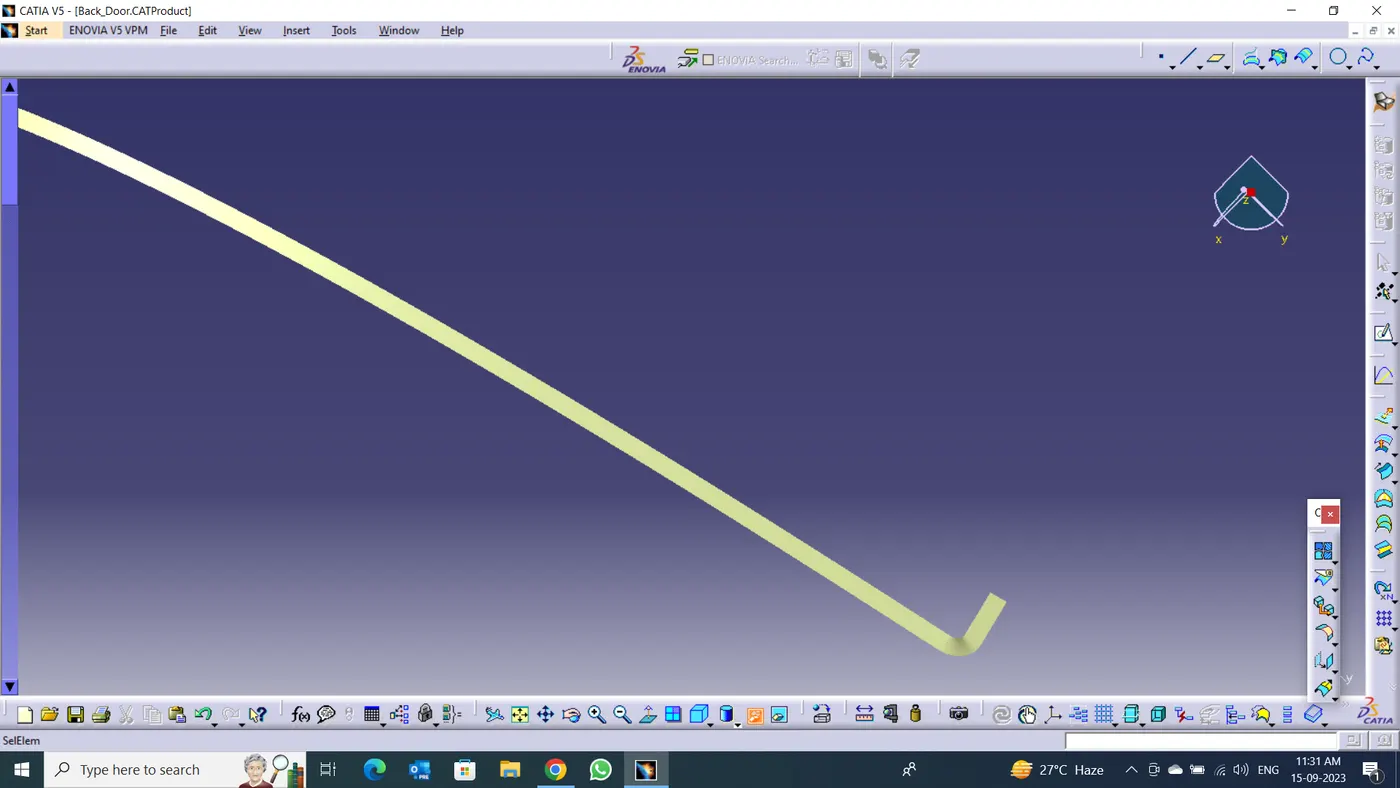
SURFACE WITH NO SHARP EDGES
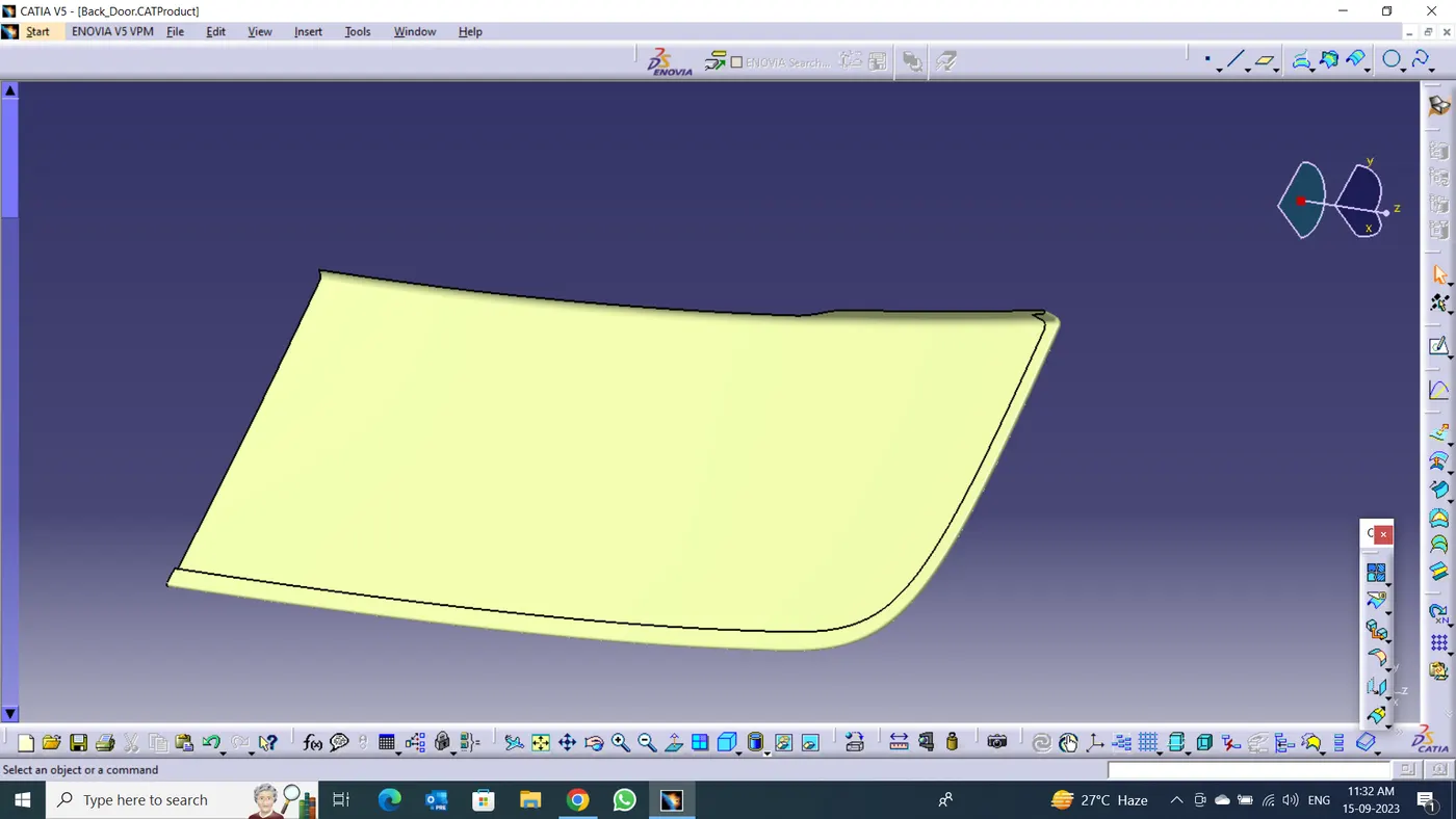
DEVELOPED SURFACE
MIRROR SURFACE :
Mirror the surface oppsite side.
- Give extra length of surface Uuse extrapolate.
- Split surface with XY Plane.
- Symmetry surface with XY plane
- join the surface.
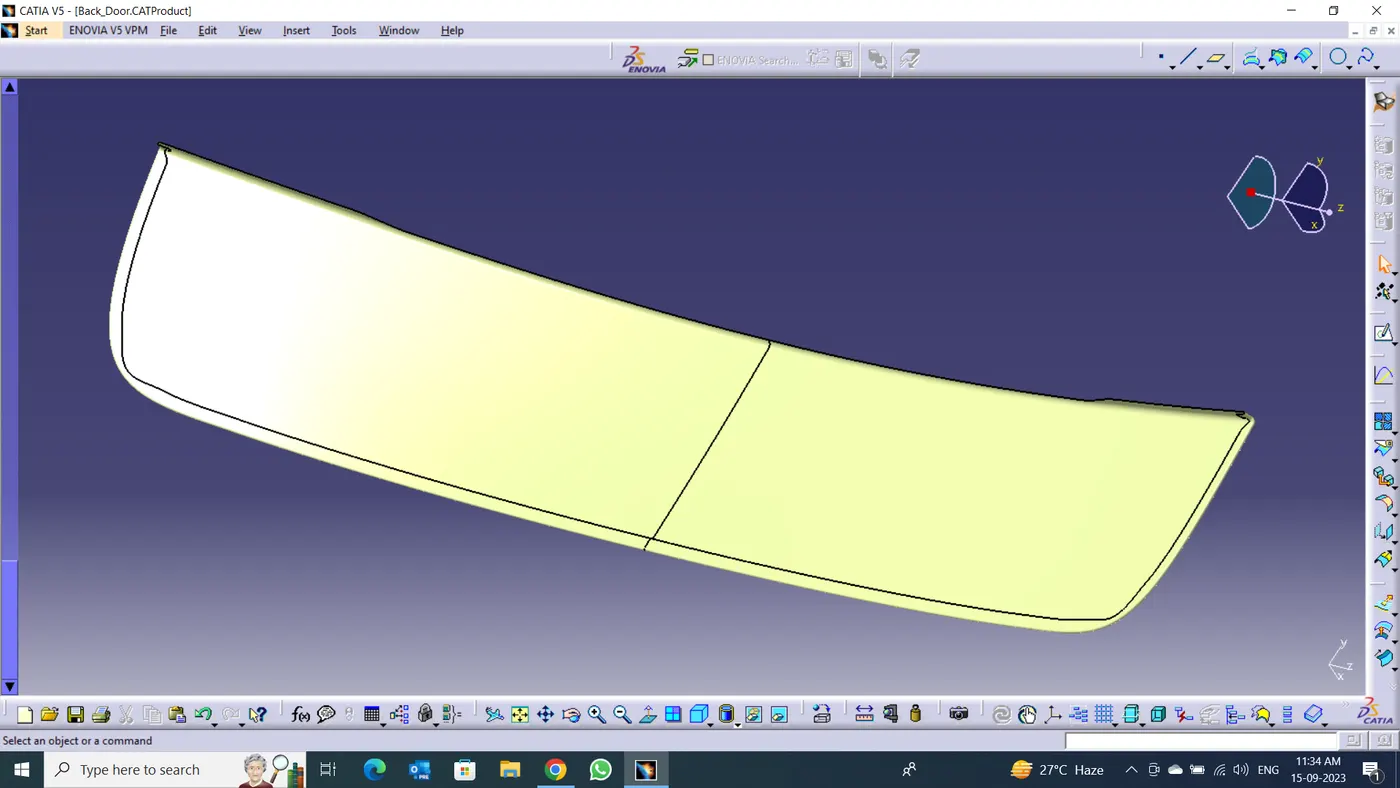
SYMMETRY SURFACE
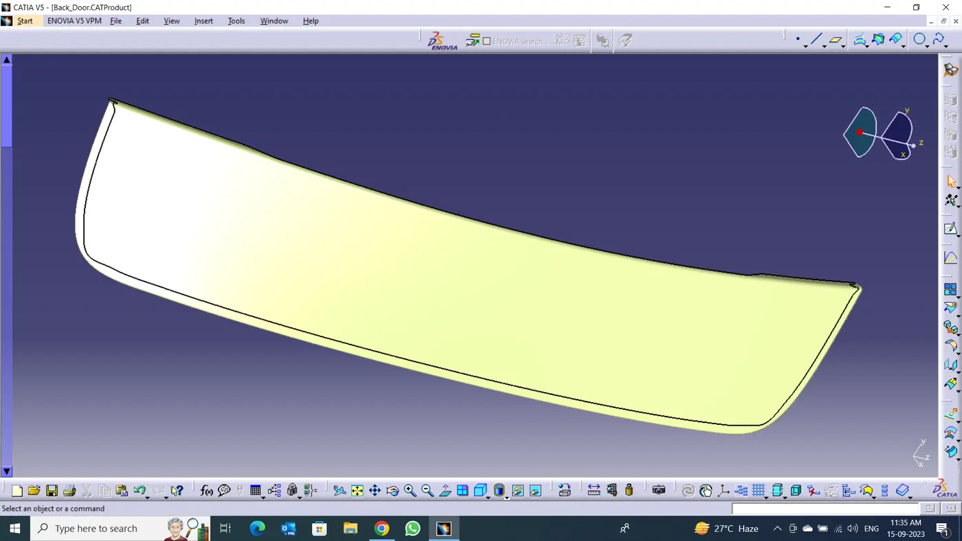
JOINED SURFACE
CONVERT PART FROM SURFACE :
- Thick the surface 0.75mm to the outer panel side.
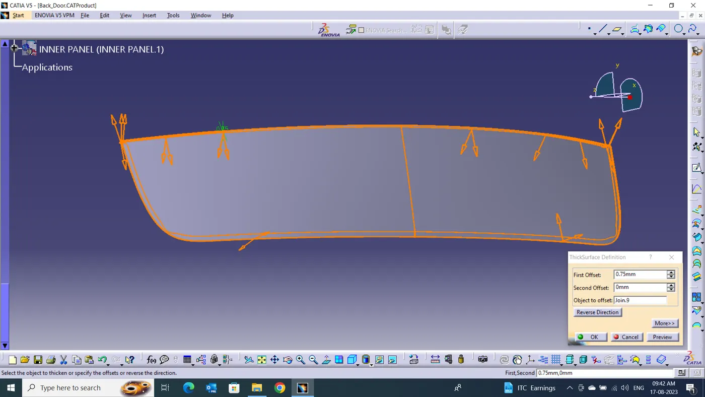
THICKEND LOWER PANEL(OUTER PANEL)
OUTER PANEL :
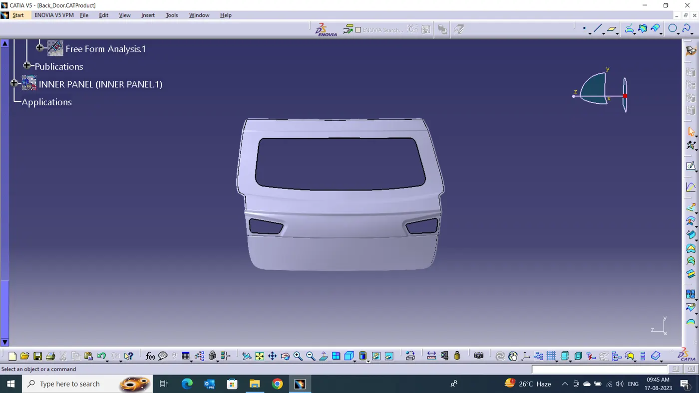
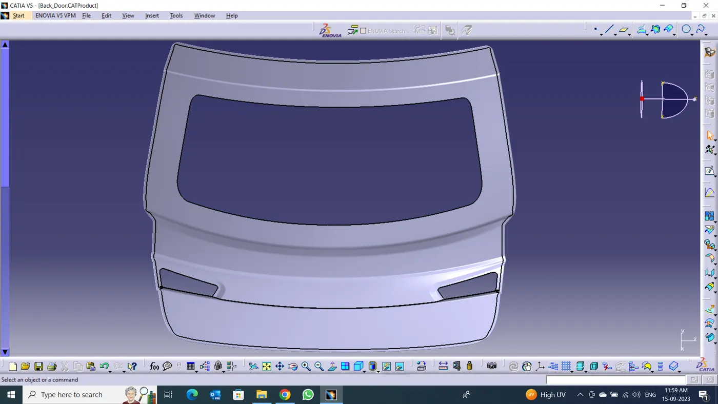
BACK DOOR :
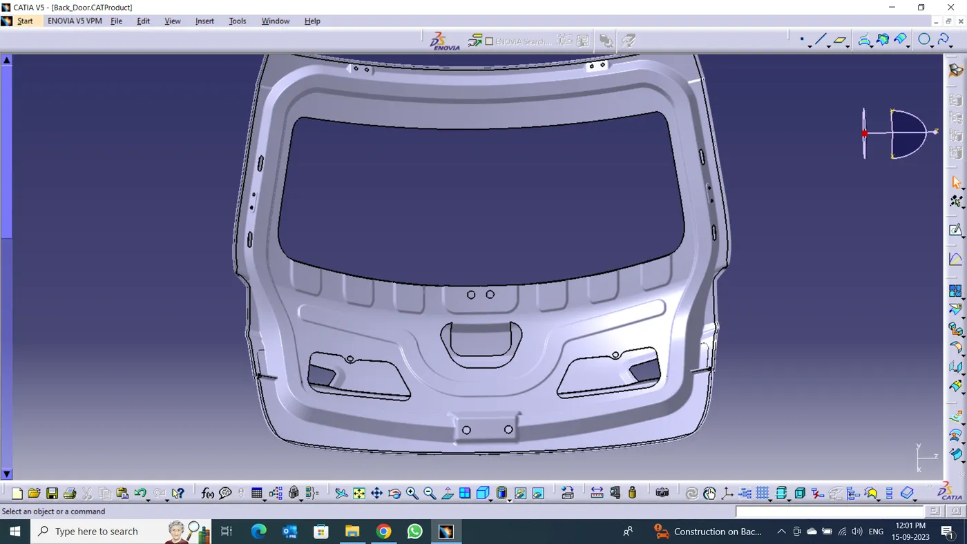
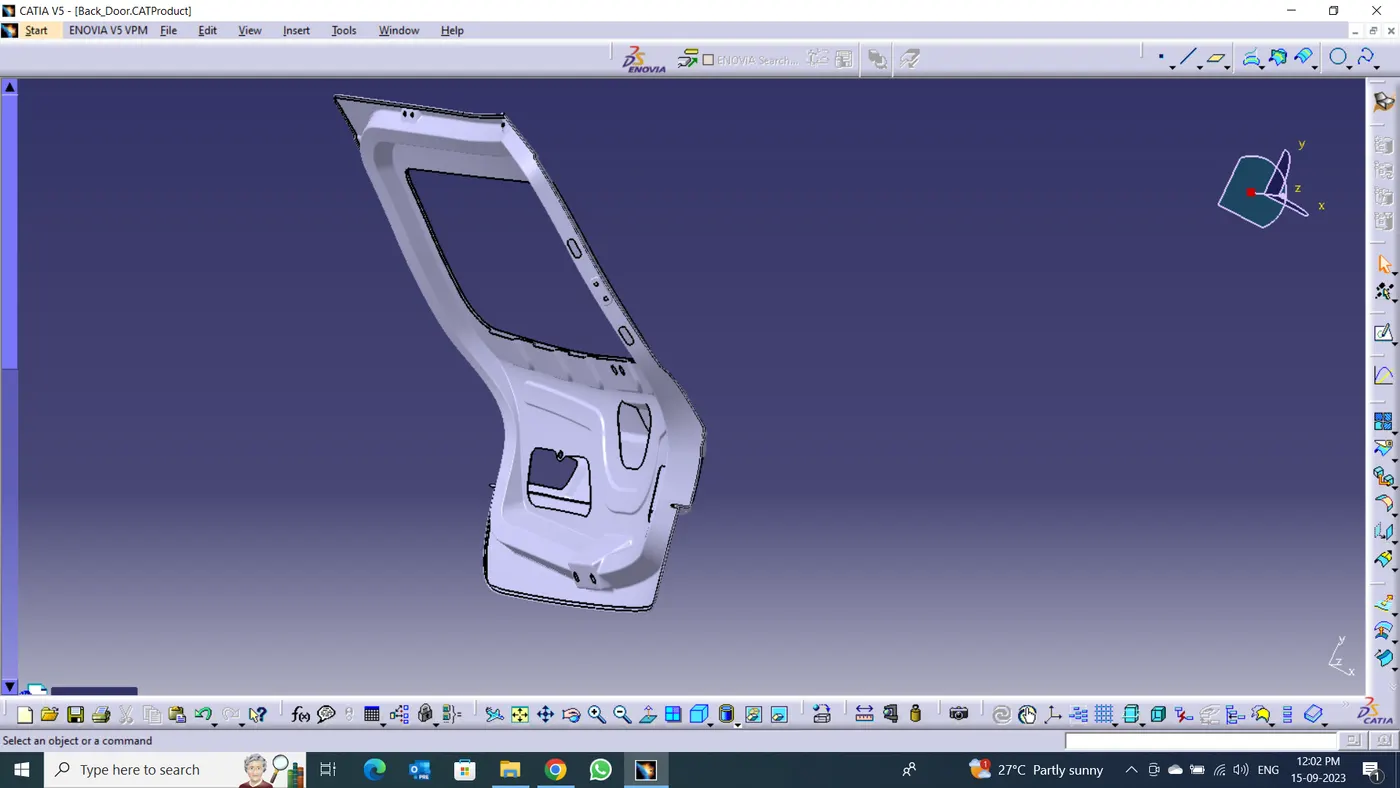
DRAFT ANALYSIS:
The Draft Analysis allows the user easily analyze a part for proper draft angle. A draft angle describes the amount of taper for molded of cast parts perpendicular to part line. Find the Draft analysis in Tools tab. Draft analysis applicable 3D part models.
To analize Draft analysis of Biw parts with angle 7°
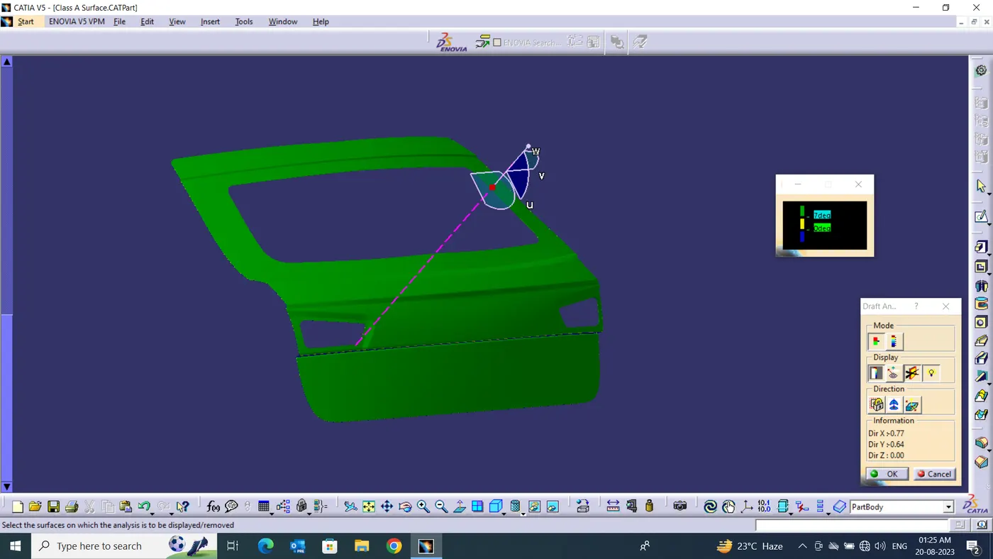
OUTER PANEL
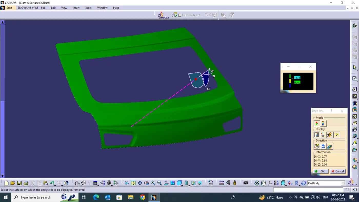
UPPER PANEL (OUTER PANEL)
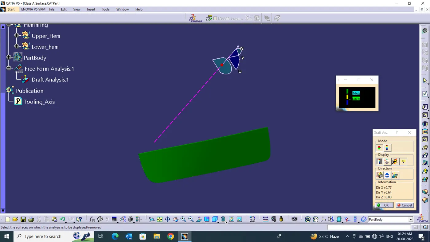
LOWER PANEL(OUTER PANEL)
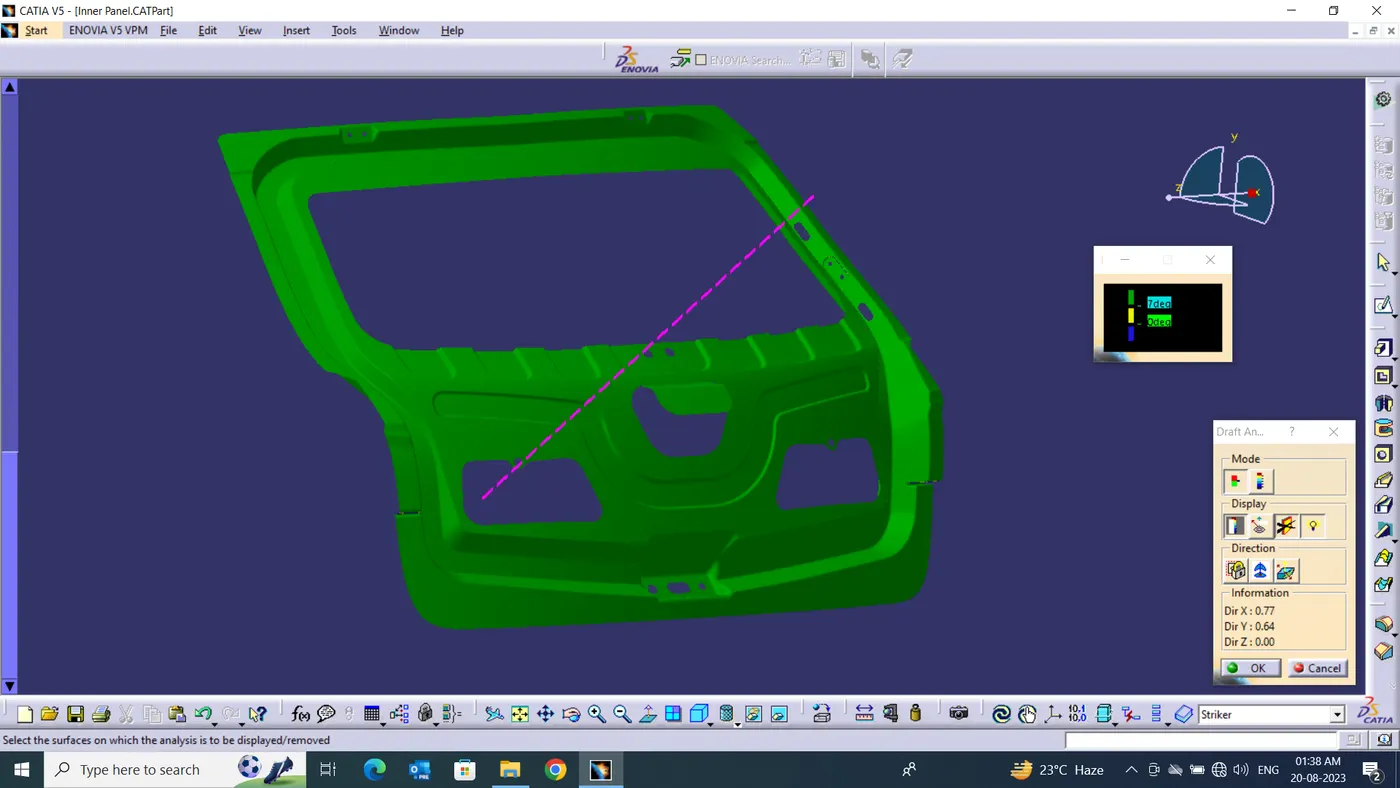
INNER PANEL
https://drive.google.com/drive/u/0/folders/1daWvmBLpb7zjKvC1Bhkel1i2LBvlQ8tE