Wiring harness routing & packaging Rules Week 3 Challenge
AIM :
Define as Electrical Supoort downloaded P-Clamp Cad data in Electrical part Workbench and define required Properties of P-Clamp.
DESCRIPTION :
CLIPS & CLAMPS :
Clips & Clamps are the Supporting features of Electrical Harness Design. Clamps are Hold wiring harnes Bundle.
Wire harness clamps provide fast, easy, reliable attachment of wire.
PROCEDURE :
DEVLOP ELECTRICAL SUPPORT IN CATIA-V5 :
1. Define Geometrical Properties.
2. Define Electrical support 1st entry.
3. Define Electrical Support 2nd entry.
1. Define Geometrical Properties :
1. Dwonload P-Clamp Cad file from website.
2. Devlop the surface use join command in Operations Tool Bar in Surface Modeling work bench.
3. Creae a Solid Part use of Closed surface command in Part design work bench.
4. Create a 2 Points use Circle Center.
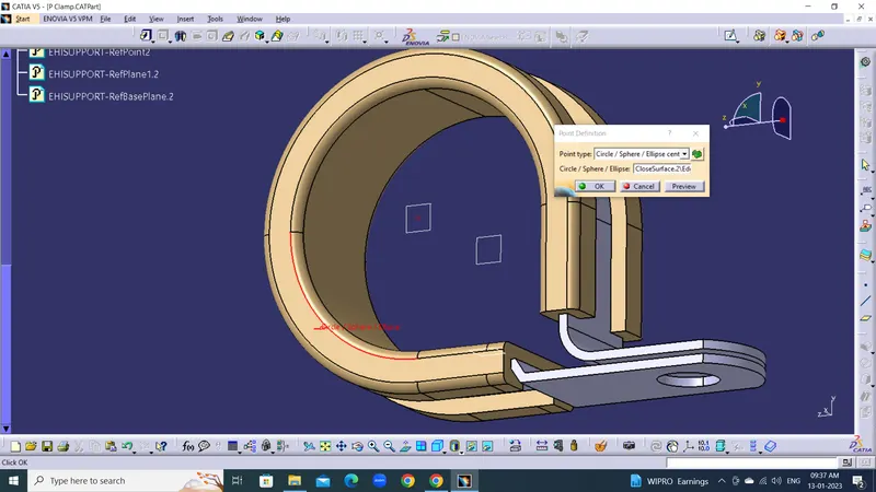
5. Create a 2 entry Planes Referance Parallel to points and Surce of component rubber body.
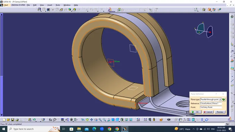
6 .Create a Support plane in base use of Parallel to plane
2. Define Electrical support 1st entry.
After apply geometrial properties open Electrical part design work bench.
1. Define Electrical support for 1st entry and exit of P-Clamp.
2. Select Electrical Support definition in Electrical part design.
3. Select 1st Entry Point and entry plane exit plane and support plane.
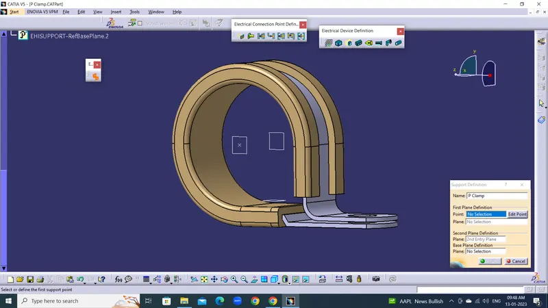
4.Define 2nd entry electrical support select 2nd entry point & Plane and exit is defult.
2. DEVELOP BACK SHEEL :
AIM :
Define as Electrical Supoort downloaded Back shell Cad data in Electrical part Workbench and define required Properties of back shell.
DESCRIPTION :
BACKSHELL
A backshell is a mechanical device threaded into the rear of an electrical connector. The more popular backshells are strain relief, cable clamps and adaptors. The SUNBANK brand offers a wide range of standard and customized backshells for the aviation and defense markets.
PROCEDURE :
Tyco 1738312-1
1. Define Geometrical Properties.
2. Define Electrical Part.
3. Define Electrical Back shell connection point.
4. Define Electrical Bundle Connection Point.
1. Define Geometrical Properties :
1. Dwonload P-Clamp Cad file from website.
2. Create a Points use Between two points named as backshell connection point.
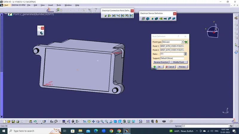
3. Create a Points use Circle Center named as Bundle connection point
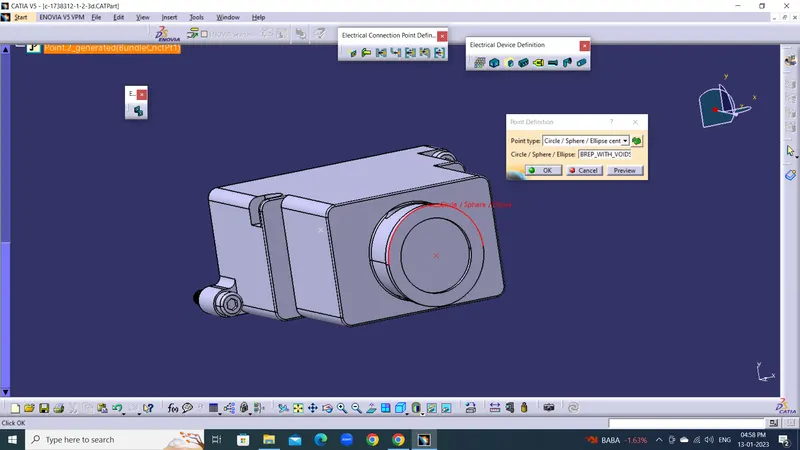
4. Create axis on Back Shell Connection Point on Point Referance.
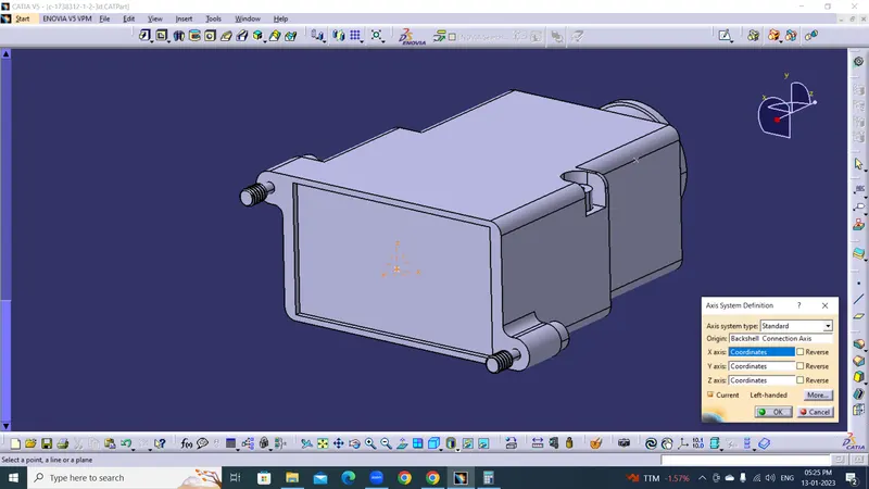 T
T
Note : Y-Axis Should be Meating Direction.
2. Define Electrical PART:
After Completing Geometrical Parmeters open the Electrical Part Design work bench.
1. Select the Define Back Shell Option in Electrical Device Definition Toolbar and select part set extra length.
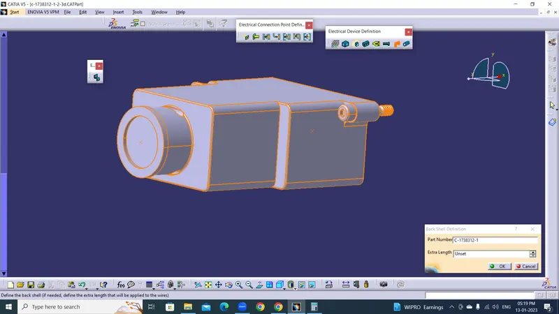
2. Now this part changes Electrical Part.
3. Define Electrical Back shell connection point :
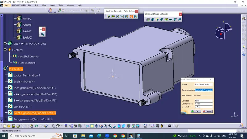
1.Select Define Elecctrical Back Shell Connection point select the part.
2. Representation is Backshell Connection point and Contact is face which meating face on part.
3. Coincidence is the Y-Axis & orentation is Z-Axis.
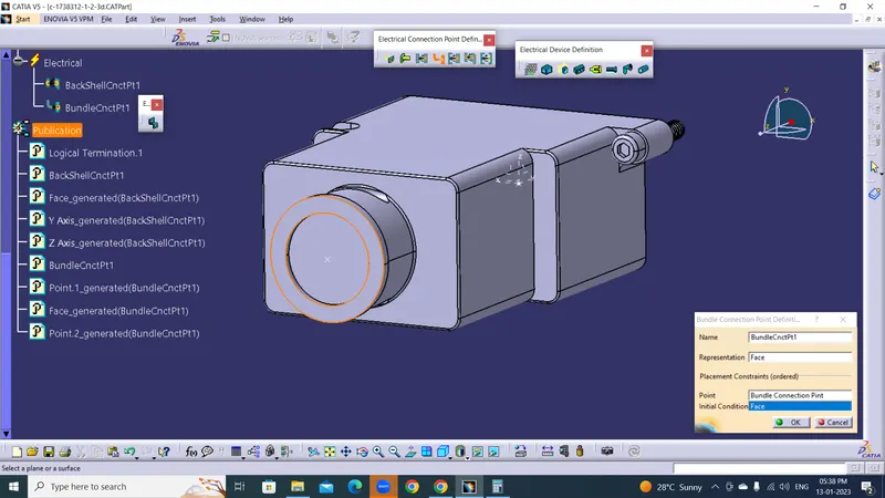
4. Define Electrical Bundle Connection Point :
1.Select Define Bundle Connection point select the part.
2. Representation is Face which is Bundle entry and Point is the Bundle Connection point.
3. Intial Condition is the fece which is Bundle entry.
3. CREATE CORRUGATED TUBES :
AIM :
To Create Corrugated tube given dimension and add in Catalogue in Slit Cot Family.
DESCRIPTION :
Corrugated Tubes :
Corrugated Tube is bellows shape and flexible, using for protect the wire harness. It is using for cars, construction machines, farm machines, consumer electronics, house, etc. We also develop functional products, improve the global supply, increase size and color of product.
PROCEDURE :
CREATE CORRUGATED TUBE IN CATIA-V5 :
1. Click on Part and select the Define Protection part.
2. Enter Inner Diameter & Thickness given.
3. Enter Bend Radius More than outer Diameter.
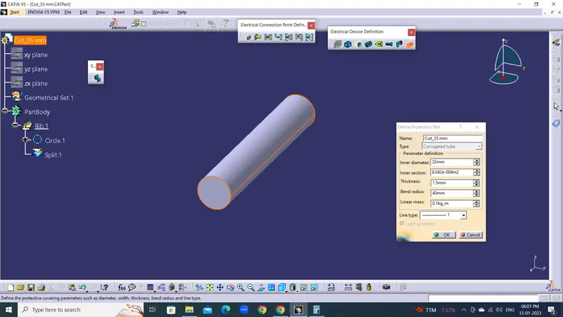
COT_ 35 mm
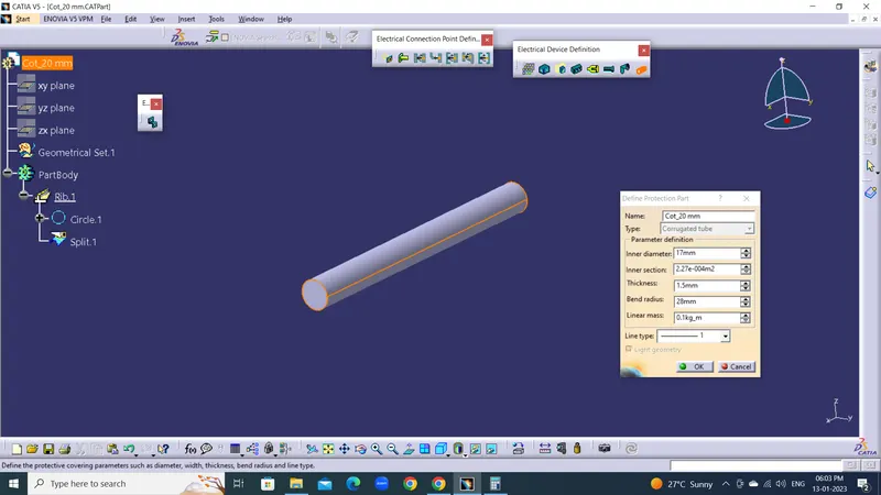
COT_20 mm
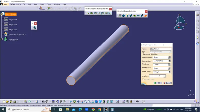
COT_ 15 mm
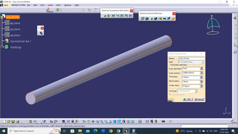
COT_10 mm
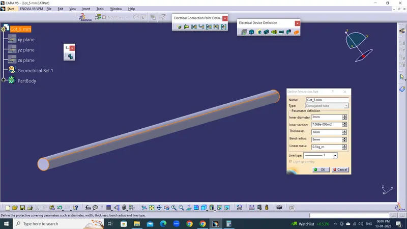
COT_5 mm
CREATE CATALOG DOCUMENT CATIA-V5 :
1. Open New Catalog Document on Catia-V5.
2. Select the Add Family enter name Slit Cot Type is Electrical and Save.
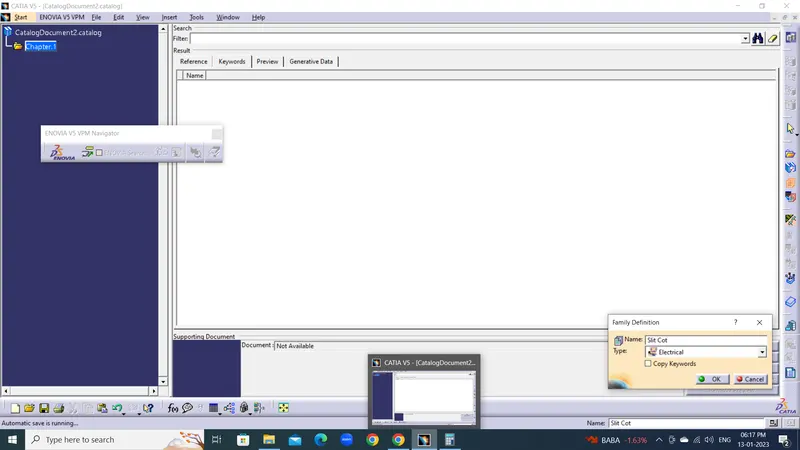
ADD COT TUBES IN CATALOG DOCUMENT CATIA-V5 :
1. Select Store Device in Electrical Part Design Work Bench.
2. Select the Catalog file and Family.
3. Add the Cot tube in the Catalog file.
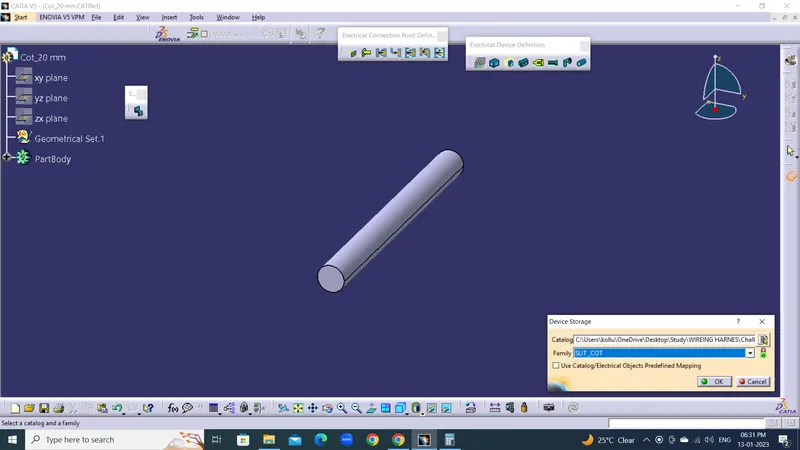
4. Add the all Cot tube same Procedure.