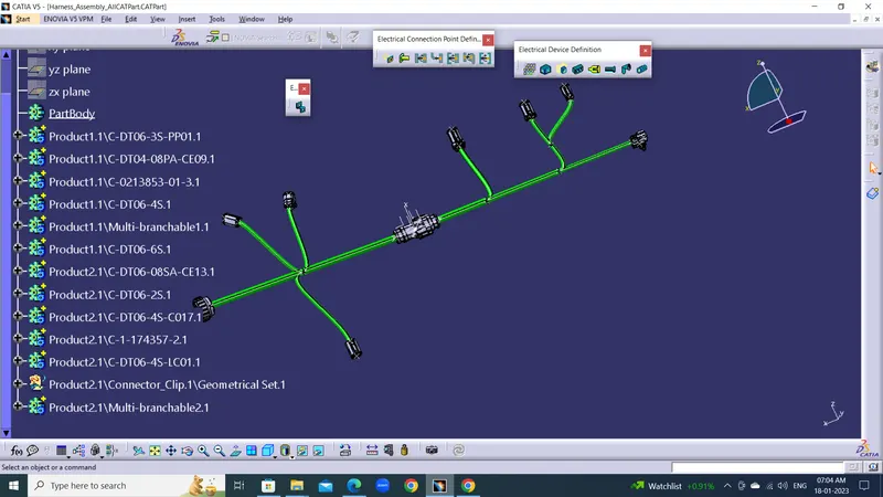
Wiring harness design in CATIA V5 - 3D modeling Week 5 & 6 Challenge
AIM :
Create a Wiring Harness Assembly Design. Check Bundle Continuity and Generate CAT Part of Wiring Haness.
DESCRIPTION :
3D ANNOTATION :
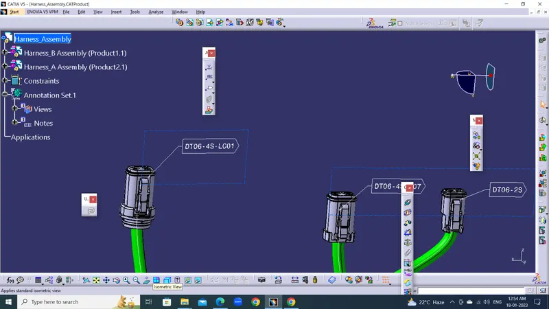
Annotations can be made to a 3D part through, for example, the Text with Leader tool, within the Part Design workbench Annotations toolbar. Additionally, these can be viewed parallel to the screen by going to their Properties and Display tab, once an annotation has been placed into the model.
CAT PART :
It may be necessary for a CAD user to create a single part from an assembly of multiple parts. Most commonly this is done when analysing an assembly using other software. Each part within the assembly is converted into its own Body within the single part, thus each part being identifiable within the part. It’s not all good news; the tool which allows users to generate a CATPart from a CATProduct is licence dependant. Those of you using the PLM Express configuration may find that having the basic CAT licence is insufficient. To enable this feature, the PLM Express configuration must have the Mechanical Product Creation (MCE) add on product as a minimum requirement.
For those of you unable to find the tool, found under Tools in the Assembly Design workbench, please leave a comment below stating the CATIA release installed and licence type available. For everyone else, watch the video below to see how it is done! 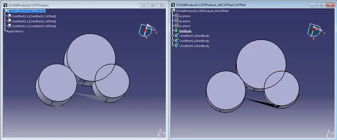
PROCEDURE :
1. Create Master Assembly for Set of Wiring Harness Assembly files.
2. Create Product assembly files in Master Assembly and develop each.
HARNESS ASSEMBLY
1. Define all Parts Electrical Properties.
2. Place the Connectors required positions.
3. Create Bundle Routing.
1. Define all Parts Electrical Properties :
1.Create a Geometrical Properties of Part Like Bundle Connection point, Connector Connection point, Connector Connection axis and Cavity Connection Point & axis.
2.Define a Part is Electrical for Connector, Cavity, Backshell etc
3.Define electrical properties of Electrically Defined Parts
Define Bundle Connection point.
Define Connector Connection point.
Define Cavity Connection point.
Define Back shell Connection point.
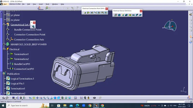
DT06-2S
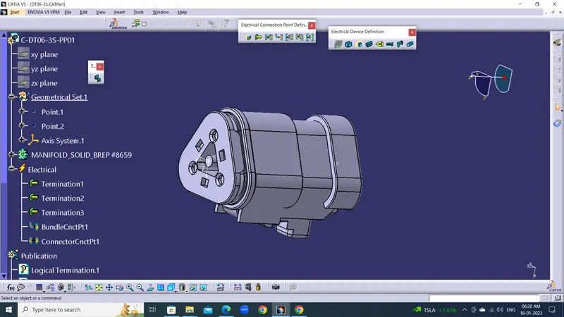
DT06-3S
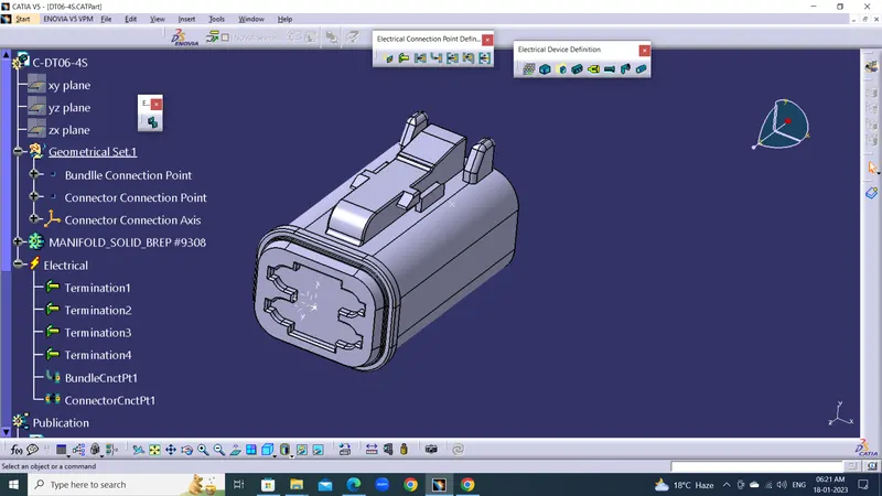
DT06-4S
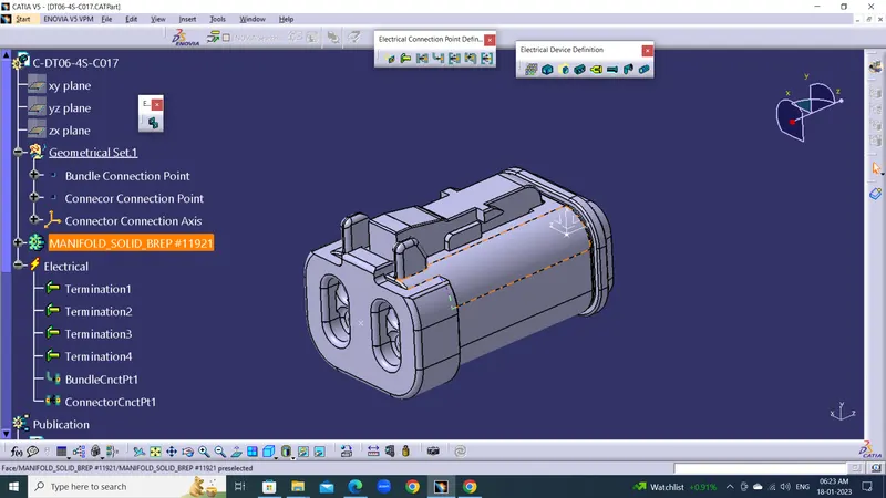
DT06-4S-C017
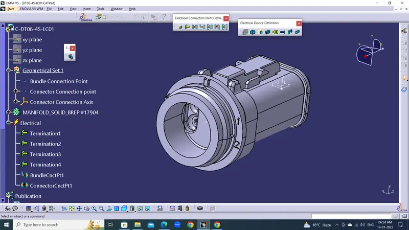
DT06-4S-LC01
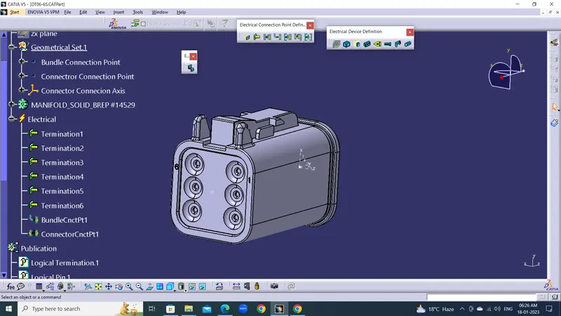
DT06-6S
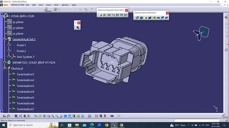
DT06-8P
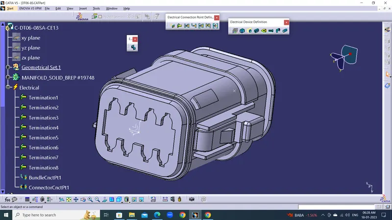
DT06-8S
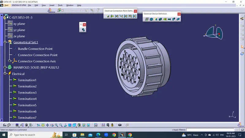
C-0213853-01-3
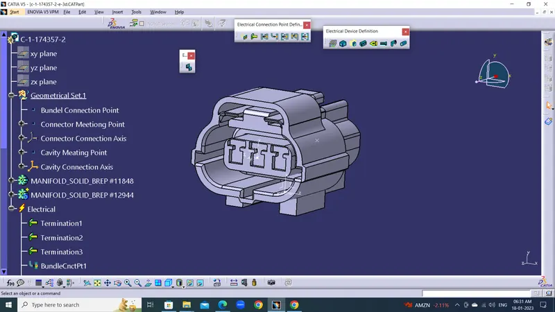
C-1-174357-2
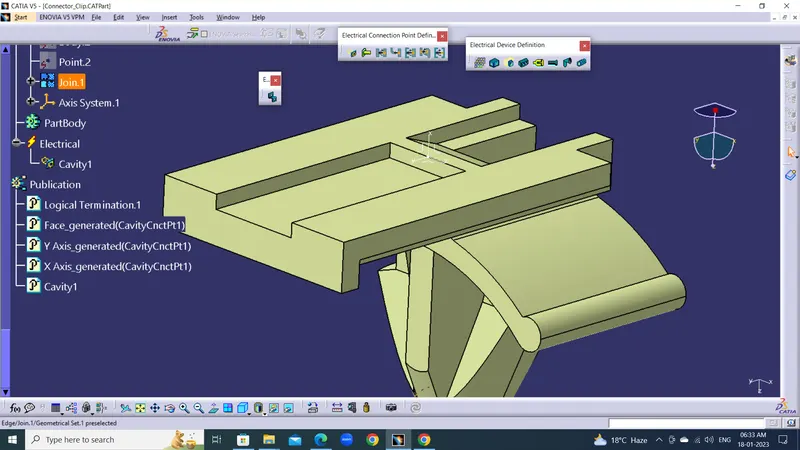
CONNECTOR CLIP
2. Place the Connectors required positions :
1. Add the Required Parts assmbly File IN Harness_B and Harness_A
2. Place all Connectors are given space use Compass, Manipulation & snap.
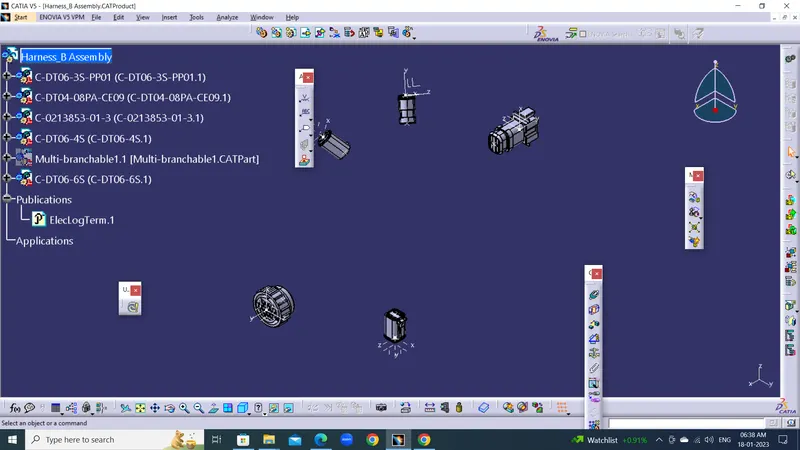
HARNESS_B ASSEMBLY
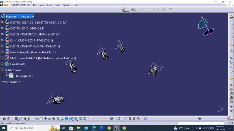
HARNESS_A ASSEMBLY
3. Create Bundle Routing :
1. Create Main Branch Bundle To link Connectors.
2. Crate required branch points in assembly file.
3. Create Sub branch bundle in file.
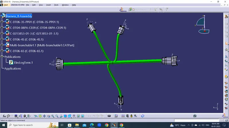
HARNESS_B ASSEMBLY
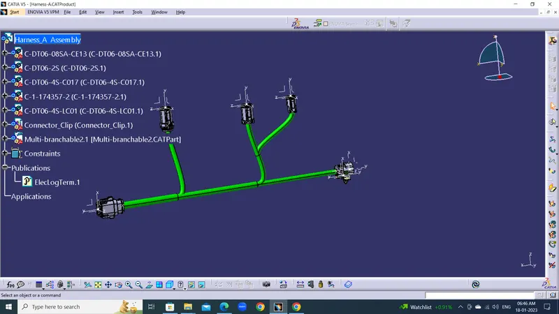
HARNESS_A ASSEMBLY
ELECTRICAL ASSEMBLY :
1. Assmbly the 2 Harness open Electrical Assembly work bench click assembly option
2. Shows the link of assembly connection in two connectors.
3. Add Assembly two harness.
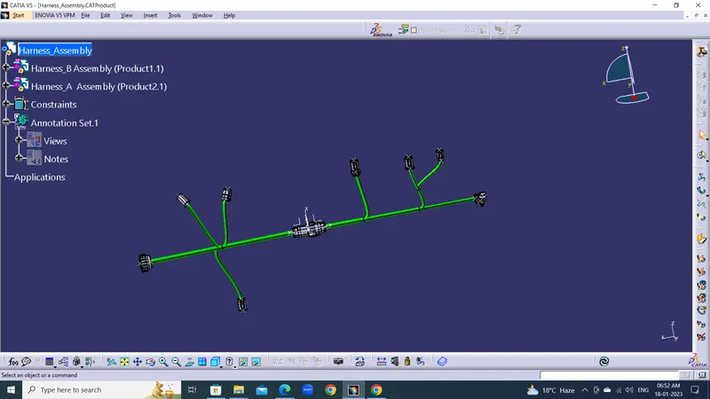
3D Annotations :
Adding 3D Annotations · Select Insert > 3D Annotation from the menu bar or, in the DMU Review Creation toolbar, click the 3D Annotation icon
Check the bundle Continuity :
Check the bundle continuity for any missing connection between budle in Assembly
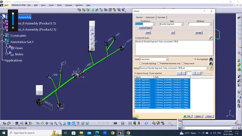
IN TRUE Statement
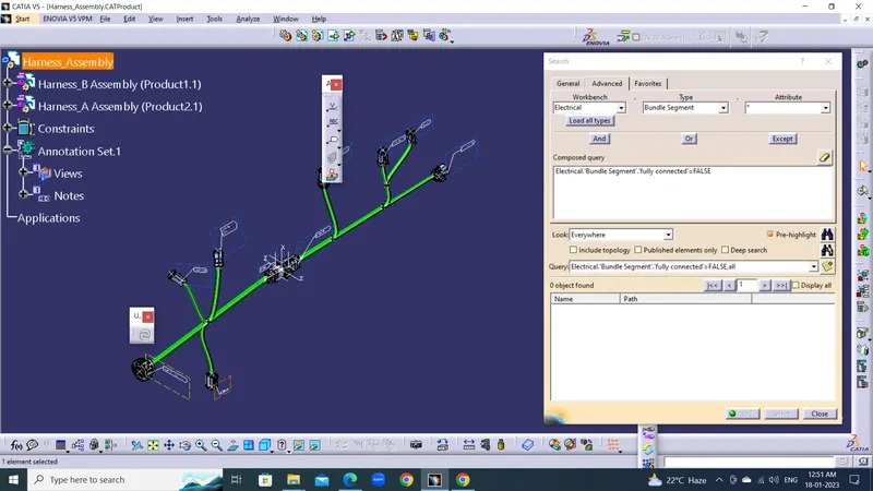
In FALSE Statement
CAT PART Creation :