Week 9 - Project 1 - Door Trim Lower with Engineering Features
DOOR TRIM LOWER :
AIM :
To be able Create a Part Body Door trim lower given class a surface. Draw B side features of Locators and Heat Staks on the Door Trim.
OEJECTIVES :
1.Creation of Tooling axis with appropriate draft angle.
2. Creation of other surfaces (eg, B and C surfaces) for creating a solid part component.
3. Create a Locators and Heat staks on the part
3.Perform Draft analysis on Class A surface and Solid model hence created.
DESCRPTION :
3-2-1 PRINCIPLE:
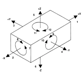
A work-piece free in space can move in an infinite number of directions. For analysis, this motion can be broken down into 12 directional movements or "degrees of freedom". All 12 degrees of freedom must be restricted to ensure proper referencing of a work-piece.
As shown in Fig 1, the 12 degrees of freedom all relate to the central axis of the work-piece. Notice the 6 axial degrees and 6 radial degrees of freedom. The axial degrees of freedom permit straight-line movement in both directions along the 3-principle axis shown as X, Y & Z. The radial degrees of freedom permit rotational movement, in both clockwise & counter clockwise radial directions around the same three axes.
Degrees of Freedom of a Rigid Body
Consider the rigid body shown below which is situated in space. It can have 12 degrees of freedom.
LOCATORS :
The Locators are the positioned features in plastic assembly, it helps assmbly the part where it assemby and it's location and arrest the translation.
There are different types of locators are using plastic assembly.
2-WAY LOCATORS:
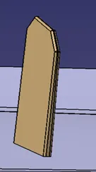
A 2-way locating pin restricts motion along 1 axis (or 2 degrees of Freedom), like a round pin in a slot. Likewise, a 4-way pin restricts 4 degrees of freedom along 2 axes. A round locating pin located concentrically in a hole is a common application of a 4-way pin, and helps to further secure the piece.
4-WAY LOCATORS:
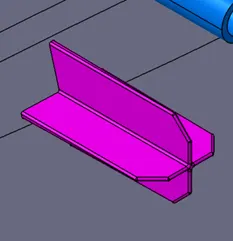
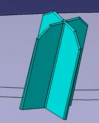
4-way mean you prevent movement at 2 axes (+X, -X, +Y and -Y) on the plane. Generally, you have cylindrical pin on the fixture and circular hole at workpiece part.
HEAT STAKES:
Manufacturing operations currently use many different combinations of attachment methods to keep components together. Common fasteners such as bolts, screws, and rivets can be used to form permanent attachments, but there are attachment methods that don’t require secondary hardware. One of those methods is heat staking, which doesn’t require additional fasteners.
PROCEDURE : -
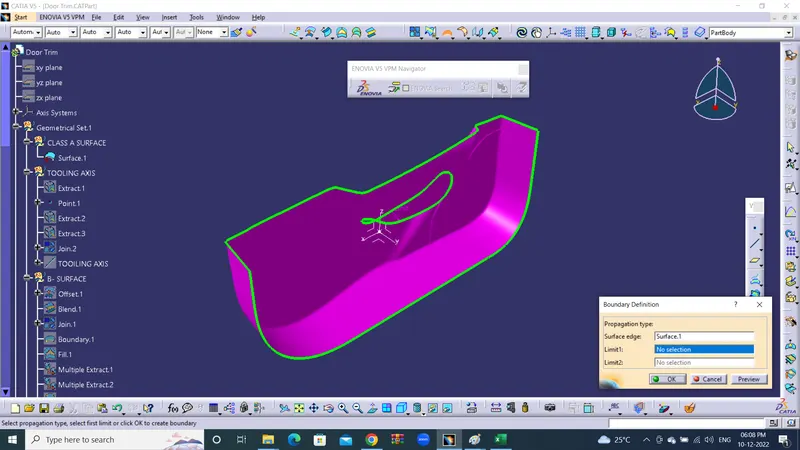
1. Define a Class A Surface weather weather any open boundary are in the surface visual verify by using of Boundary feature.
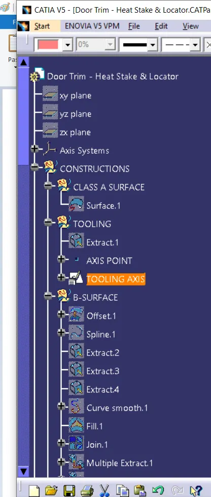
2. TOOLING AXIS
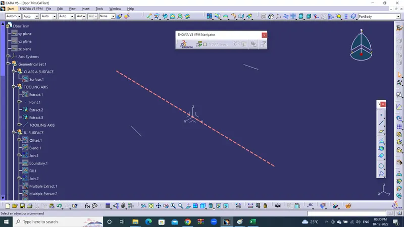
It is defined as the direction in which the mould/core and cavity open. Selection of the direction of the tooling axis depends on the ease at which components can be easily ejected.
By analysing the component the most easily ejectable direction is somewhere close to the Z direction,(might be inclined to it) so we have made a sketch on the YZ plane of Axis System) to create a bisecting line considering the 2 faces which might be difficult to be tooled.
3. B-SURFACE
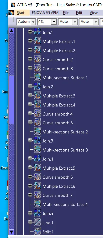
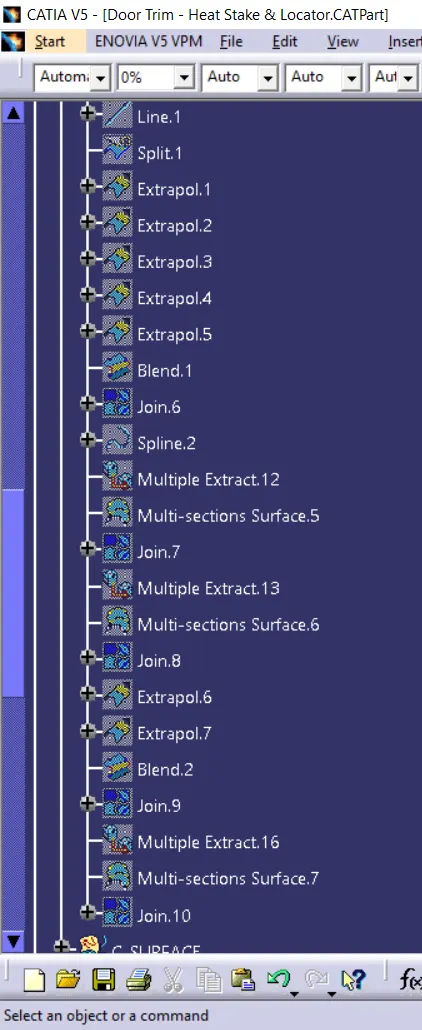
To create the class B surface, offset the class A surface inside as per our thickness requirement (here the thickness is 2.5mm, so I offset the class A to 2.5mm inside). Once the offset is created, we can observe some patches on the offset surface by taking the boundary for the offset surface, those patches are formed due to the fillets on the class A surface. We need to cover those patches with the help of the multi-section surfaces command by extracting the patch boundaries. Once all the patches on the offset are covered properly join all the patches with the offset surface, to get the replicated surface of the class A surface. Later Extrapalte B surface.
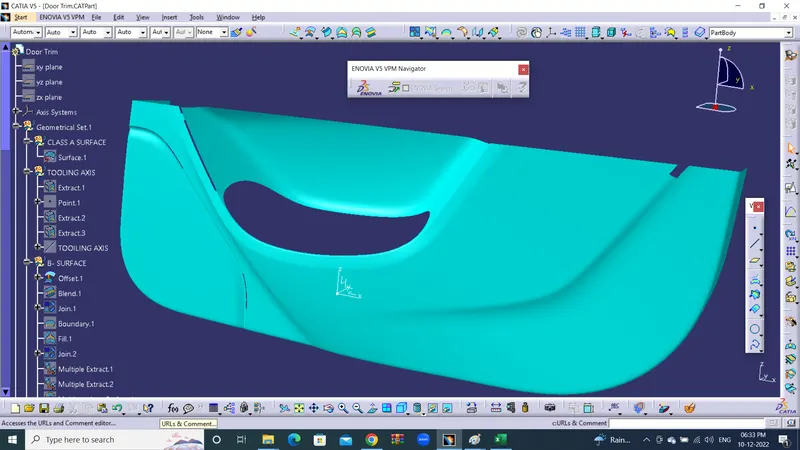
INTIAL B-SURFACE
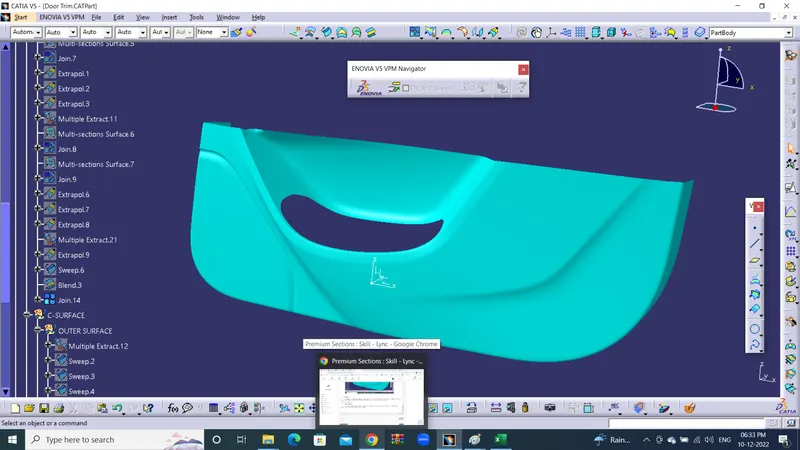
FINAL B-SURFACE
4. C-SURFACE
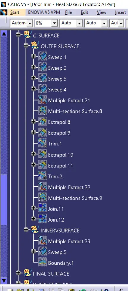
To create C-Surface with the sweep command Boncerning the boundary of the class A surface. Initially, Created Multi extract of Class A Surface and later sweep surface at 87deg (for draft angle) for 3mm Both Outer and Inner C-Surface.
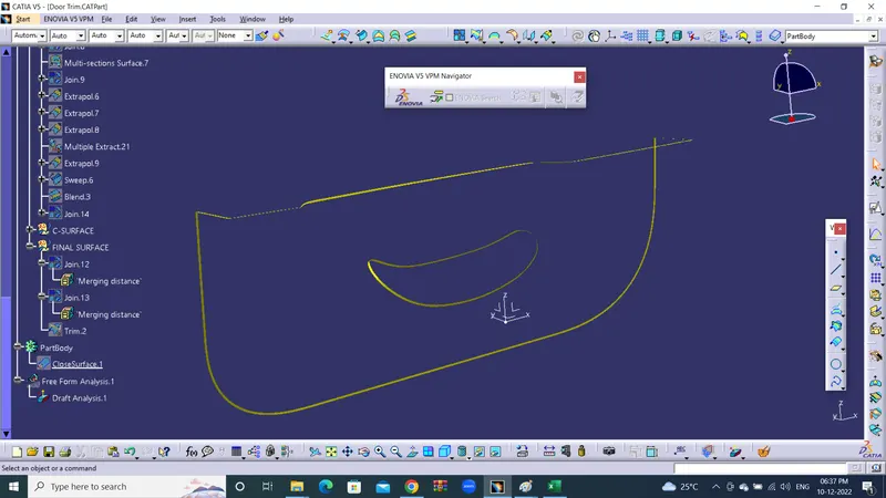
Note: Verify Open Surface
5. FINAL SURFACE
In the Final operation Jion The Class A Surface and C- Surface Outer and Inner. After that Verify the Join surface any open boundaries. Finally Trim The Join surface with B- Surface.
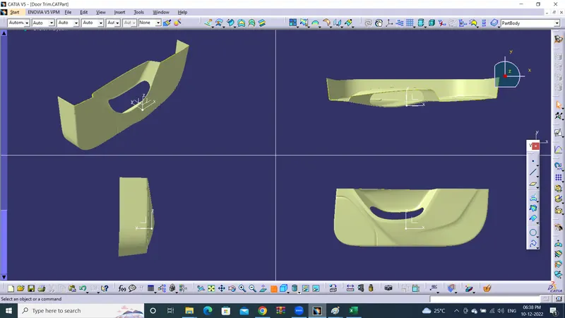
6.SOLID BODY
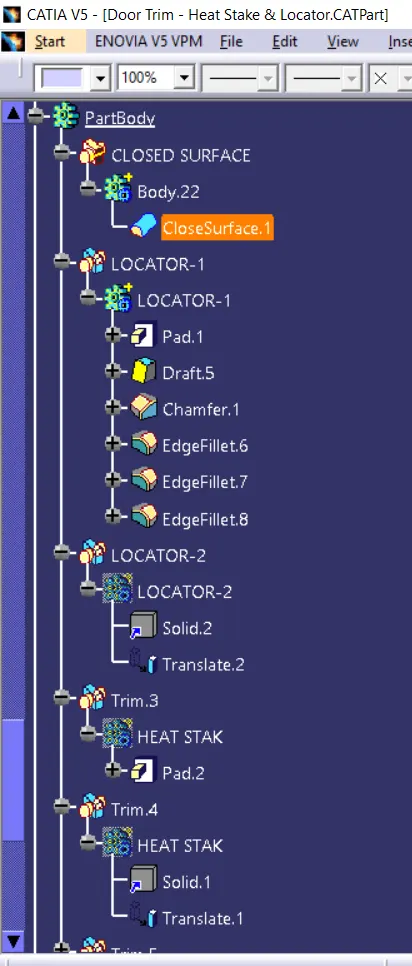
Let Final do the ope Part Design In softwae and Select the Closed Surface Command in part Modeling.
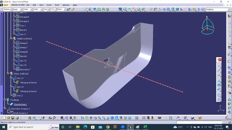
7. B SIDE FEATURES
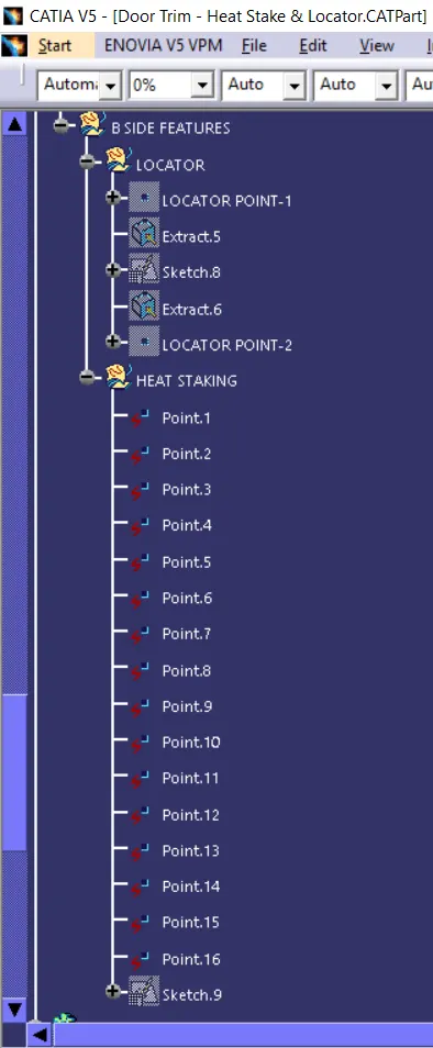
LACOTORS :
The 4 way locator place in 2 place in part of Door trim lower part. To Create a 4 way locator create a two Lines perpendicular each oher, Create a pad thick 2mm with symtray and draft 0.5 dire pulling direction of tooling axis.
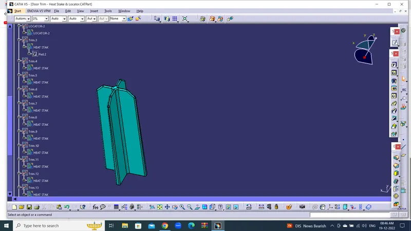
HEAT STAKS :
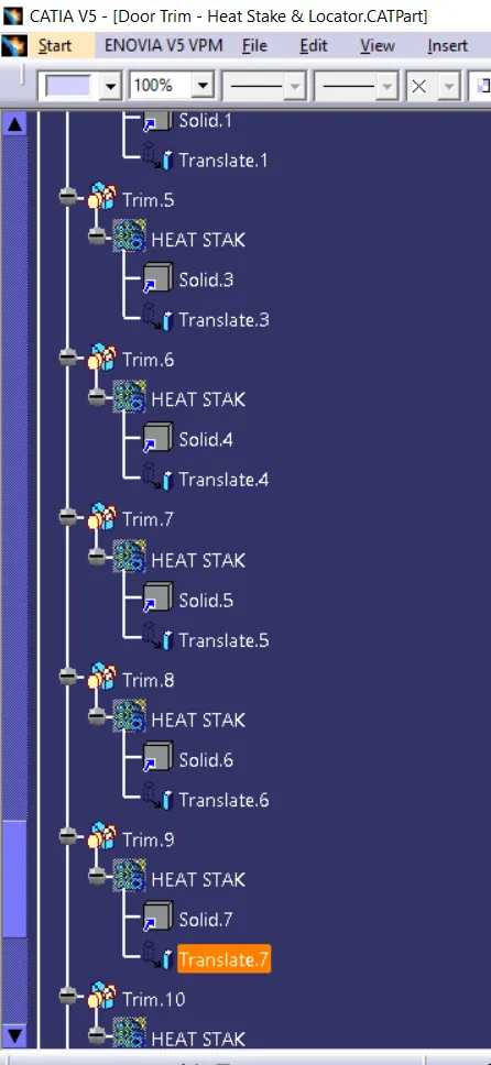
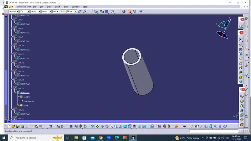
To Create heat staks draw a sketch 2 circle and pad the sketch, Draft the outer and inner faces pulling direction of tooling axis.
Copy the body and paste special and transalt point to point method all.
8. ATTACHMENT :
ADDING LOCATORS :
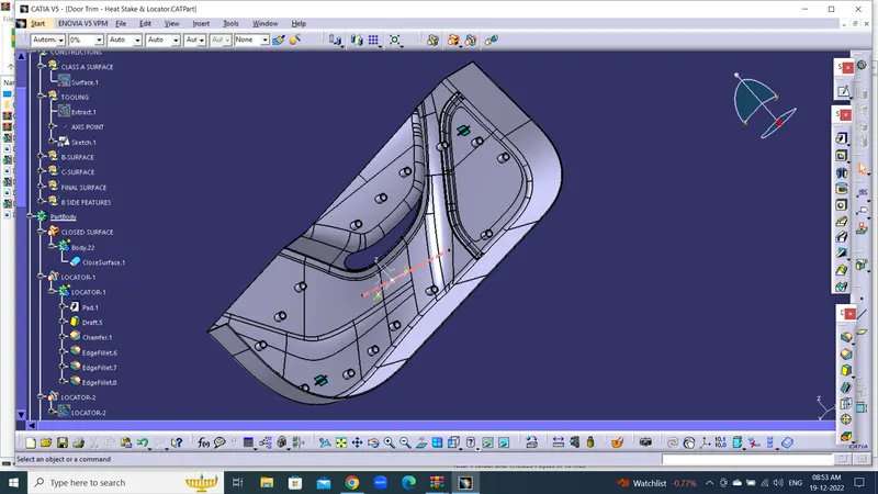
To add the feature yo body ADD, Interct, Union trim Add the locators by using union trim main body.
ADDING HEAT STAKS :
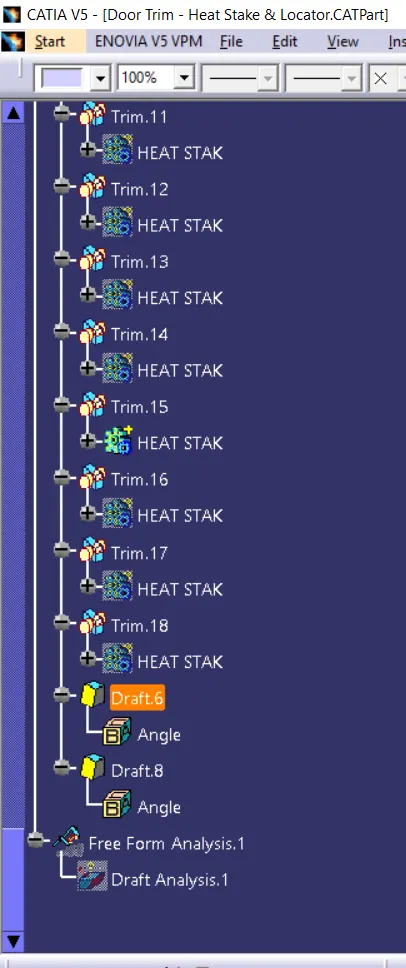
Add the Heat staks using union trim.
DRAFT ANGEL ANALYSIS
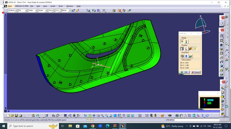
The draft is the amount of taper for moulded or cast parts perpendicular to the parting. line. Draft angles are a design consideration that makes it much easier for a part to release cleanly from a mould. A draft angle is calculated as a degree measurement (or, less often, an inch or millimetre measurement) from the vertical axis of a mould, and it helps account for thermoplastic shrinkage, a practical reality of the injection moulding process for most materials.
Draft angles are generally a requirement of injection moulding design (though there are a select few soft materials, like nylon, that can get away with draft angles of zero). The draft should be a part of the design for manufacture, and all stakeholders and contributors should be aware of its need at the outset of the design process. This includes product designers, design engineers etc and this allows considerations for design requirements to be taken into account. Any draft is always better than no draft.
TREE STRUCTRE :