Roof Design
ROOF DESIGN
AIM:
To be able to Design & Develop Car Roof given surface with its components by following the master section and design parameters.
OBJECTIVES :
- To Develop Roof with 0.75 mm thickness following master section.
- Design and Develop Front Roof Rail and Rear Roof Rail with design consideration.
- Design and Develop Bow Roof, Center Roof Rail, Sun Roof.
- To develop the essential flanges and reinforcements using roof styling as input.
- To do a curvature study on the roof and perform calculations to determine the position of the Bow-roof.
- To determine the Heat Distortion Criteria of the car's roof.
- To find the section modulus on the O-Y section of the roof and also for all the components of it.
- To determine the Snow Load Criteria for a car's roof.
INTRODUCTION :
An automobile roof or car top is the portion of an automobile that sits above the passenger compartment, protecting the vehicle occupants from sun, wind, rain, and other external elements.
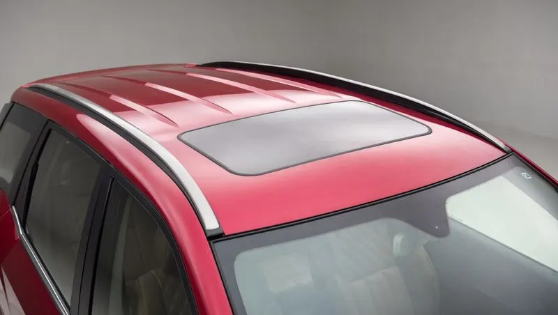
An automobile roof is considered as an integral part of BIW (body in white) design. It also offers aerodynamic support to the car when it is in motion. A roof panel assembly includes a roof outer panel/ditch area and inverted hat like reinforcements rails which underlie the outer side edges of the roof outer panel. Roof rails are provided to give strength to the outer panel and also provide support to other commodities present in a car.
There are different rail reinforcements in a roof panel like:
- Front roof rail
- Rear roof rail
- Bow roofs
- Center Roof
- Sun Roof
Reinforcement roof centre
DESIGN CONSIDERATION
Geometric requirements:
- Thickness – .75 to 1.5 mm
Manufacturing requirements:
- Small emboss depth should be less than 6 mm
- Mounting and welding areas should be flat
- Minimum fillet radius should be 3mm+thickness
Functional requirements:
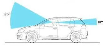
1. Rear headroom clearance: 80mm minimum
2.Rear visibility criteria
3.Space for mounting the backdoor hinge
Master section:
Master sections are the 2D outlines which is taken at a particular area of a 3D model or it is an intersection of 3D model about a reference plane to study its outline (or boundary) in a 2D view. These master sections are widely used in OEMs and in automotive industries to convey the functional requirements of commodity to the design engineer.
It gives the parameters like length, width, height, radius and clearance should be considered while designing the particular part or component.
For this project it gives the parameters to be considered while designing the roof outer panel, front roof rail, bow roof, centre roof and rear roof rail.
1.Roof outer panel & front roof rail master section:
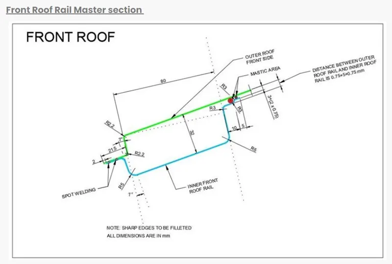
According to this master section, the front flange should have the 7º draft angle and following this it gives flange distance of 21.5mm to the front flange. Then it gives the radius value of 2.2mm for blends.
- These are all the minimum values to be maintained in the roof outer panel design according to the engineering standards.
- Some of these dimensions are also considered to develop the ditch area at the sides outer panel.
- The following front roof master sections gives parameters, which Concerning the field of vision for driving and head room for the occupants.
- The front roof rail is going to be assembled with the outer roof panel by means of spot welding at the front flange area. So, the offset of front roof front flange is 0.75+0.2+0.75mm from the outer panel front flange.
- Then the offset for emboss is 32mm for the front roof from the roof outer panel and its length should be of 80mm from the outer panel front flange.
- The rear flange of the front roof is 15mm distance from the emboss end and it is further divided into 10mm & 5mm.
- This flange has the offset of (0.75+5+0.75mm) & (3+2*0.75mm) from the outer panel, those variations are to provide clearance for mastic sealant to expand, while assembling it with the outer panel.
2.Bow roof master section:
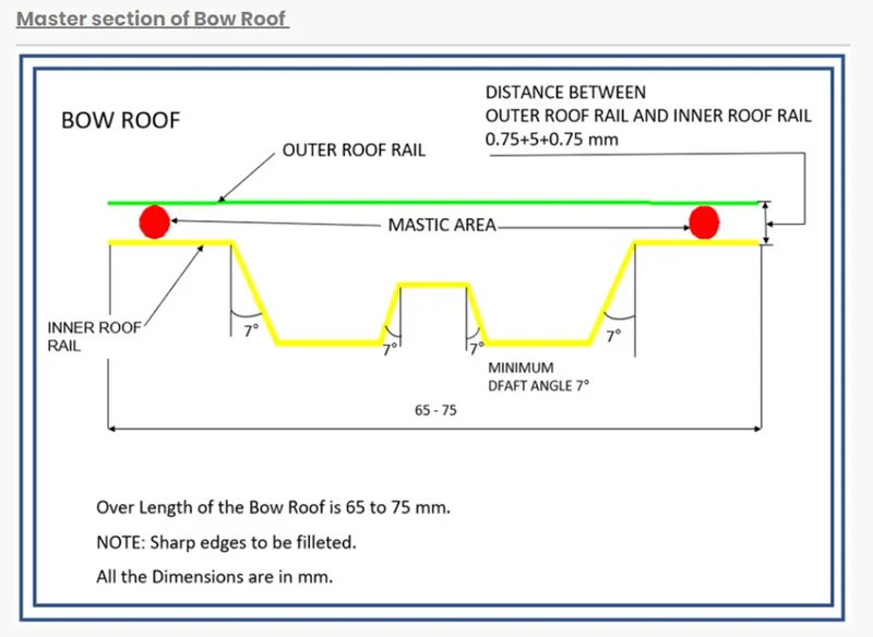
According to this master section, the overall width of the bow roof should lie between 65-75mm and all the embosses should have atleast 7º of positive draft with respect to the tooling direction. Then the offset of bow roof outer flange is 0.75+5+0.75mm from the roof outer panel and the placement of bow roof should be in the flatter region rather than the curvy region of roof. These parameters are same for all the bow roof section.
3.Center roof master section:
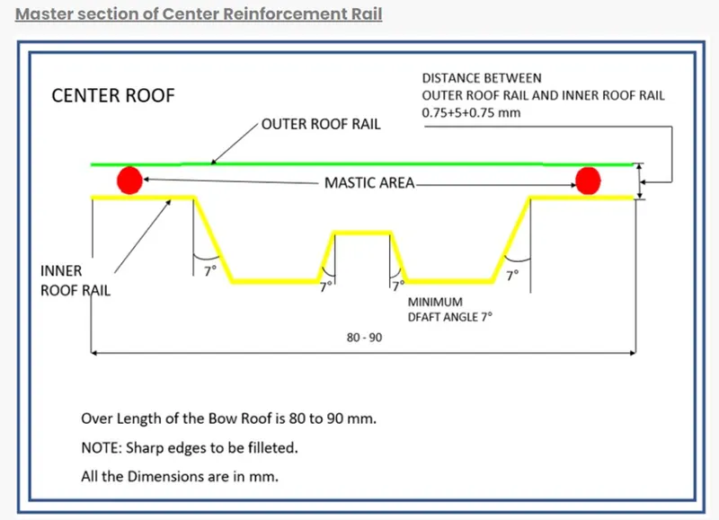
According to this master section, the overall width of the center roof should lie between 80-90mm and all the embosses should have atleast 7º of positive draft with respect to the tooling direction. Then the offset of center roof outer flanges is 0.75+5+0.75mm below the roof outer panel. The center roof is placed at the region were the B-pillar connects with the roof.
4.rear roof rail master section:
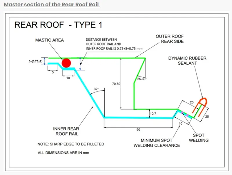
This master section gives the dimensional parameters for outer roof panel rear flange and rear roof rail.
- The outer roof panel rear flange should have the negative flange of 25º-30º draft to accommodate the clearance for back door movements.
- The overall hight of the rear flange must lie between 70-80mm, following this the outer most flange should have the required dimensions for spot welds and back door placement.
- Then the parameters for rear roof rail are offset of (3+0.75*2mm) & (0.75+5+0.75mm) for front flanges, 10.7mm for the offset of center emboss and its width is 90mm. Then the draft angle for emboss connecting the front flange is 32º.
PROCEDURE FOR DESIGN & DEVELOPMENT:
ROOF :
1. To be develop the Roof import file in to CATIA V5 Software.
2. Extract the surface and offset it.
3. Devlop the Flages as Design Considerition and master section by Using Sweep and Mullti section surface.
4. Now Join all Surface and apply Radius in all Corners.
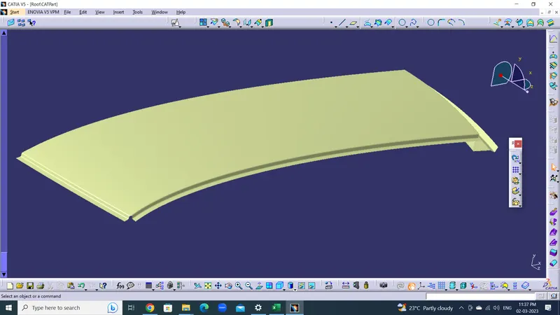
5. Now Mirror the surface using symmetry option.
6. The Developed surfaces will give Thicken Surface option 0.75mm thickness.
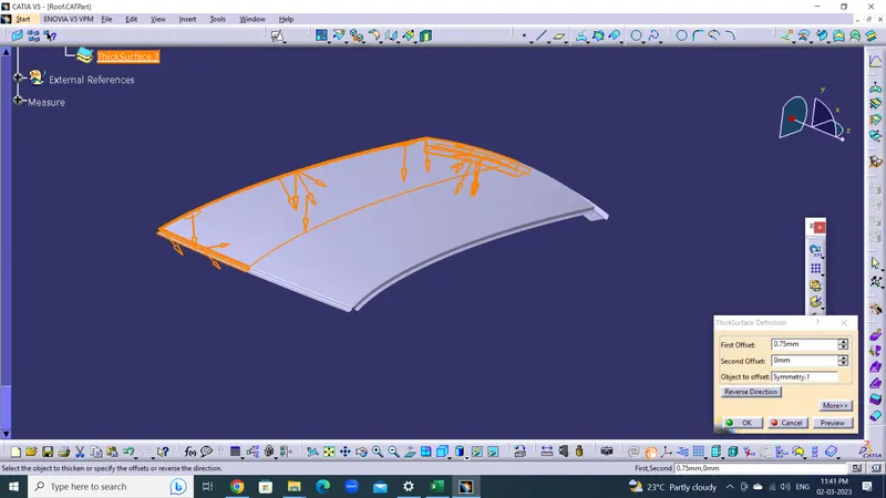
FRONT ROOF RAIL :
Front roof rail is used to provide strength to the roof panel front and it also acts as link between windshield glass, roof panel and headliner(interior trim). Headroom clearance and visibility are two important criteria for the driver and both of them depends upon the front roof rail dimensions, hence it is important to select appropriate dimensions for the roof rail.
To be able to Design a Front Roof Rail mastese Master section.
Extract Surface of front fllange and offset it 0.75+0.20+0.75 mm. Extract other surface with 0.75+5+0.75 mm master sections.
To Develop Front rail use sweep, multi section surface, Split, Trim & Fill commands. Developed surfaces convert thick surfaces 0.75 mm
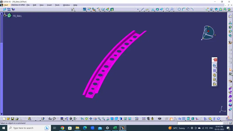
FRONT ROOF RAIL
REAR ROOF RAIL :
Rear roof rail is to design same procedure use master section for rear rail
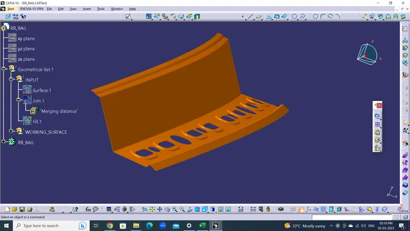
REAR ROOF RAIL
A Bow roof is a sheet metal part, usually spot welded to the BIW inner frame, forming the inner structure of the vehicle body. Its primary function is to supporting the roof panel loads, such as Oil Canning and local stiffness
To Design Bow roof Spilt the surfaace referance of master section. Extract and offset 0.75+5.00+0.75 mm and offset other surface also. Develop the offset surfaces use of sweep surfaces and join
Thicken the devloped surface 0.75 mm
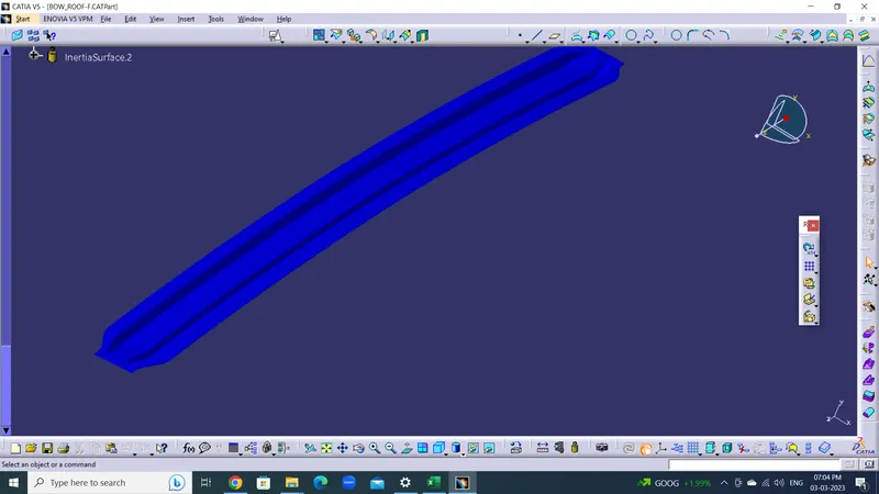
CENTER ROOF RAIL
The roof rail is a feature that is found predominantly in estate cars or vans. Roof rails serve as a basic support for transporting things on the roof. With their help, the car can be put to varied use if the interior is already full.
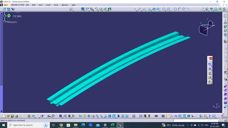
SUN ROOF
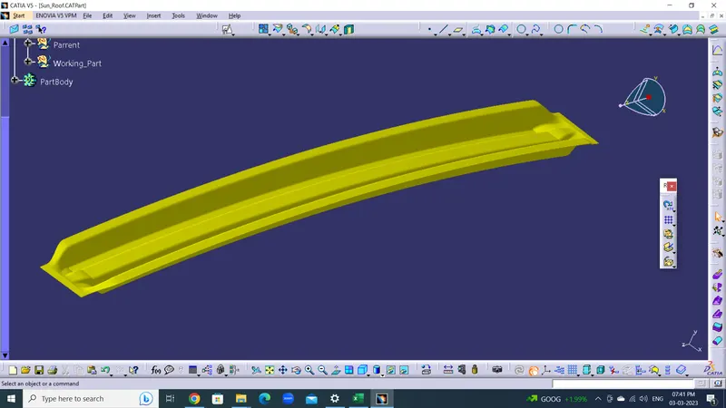
A sunroof is a movable panel that opens to uncover a window in an automobile roof, allowing light and fresh air to enter the passenger compartment. Sunroofs can be manually operated or motor driven, and are available in many shapes, sizes and styles.
HEAT DISTORTION CRITERIA :
- To calculate the Heat distortion criteria, we have to take a note of few values and note it down.
- To note down the values, first, we need to create a sketch.
- Create a line at the center of the roof part in the 0-Y axis and then draw another line with a distance of 300mm to the O-Y line.
- Now create lines at a distance of 100mm on both sides to the 300mm line.
- Create a new sketch in which we need to create lines between the bow roofs and rails coming at the center. These lines need to be created in X-direction.
- Using these center line create lines at a distance of 100mm on both sides.
- Now intersect sketch 1 (lines in Y-direction) and sketch 2(lines in X-direction). This result will give us some points where the lines (X & Y)are coinciding with each other.
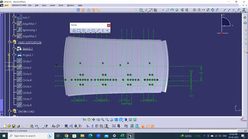
- Extract the required points and project them on the roof surface. Now using these points create a 3 point arc or circle and note the radius of the arc in the X direction as Rx">Rx and in the Y direction as Ry">Ry.
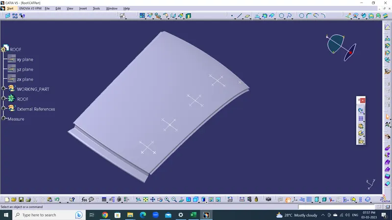
Now since we got all the values for calculating the Heat Distortion, substitute these values to the below equation.
W = [1.73 x 10^(-3) x L] + [1.85 x 10^(-8) x (R^2)/t] + [ 1.10x10^(-3) x l] - 2.68
| HEAT DISTORTION CRITERIA | |||||||||
| RX | RY | R | I | L | t | (R^2)/t | W | RESULT | |
| FRR-BR1 | 5737.68 | 2470.32 | 3453.68 | 328.757 | 2023.44 | 0.75 | 15903886 | 1.12 | TRUE |
| BR1-CRR | 4976.72 | 6176.62 | 5512.13 | 426.218 | 2023.44 | 0.75 | 40511424 | 1.57 | TRUE |
| CRR-BR2 | 3983.8 | 10549 | 5783.47 | 427.709 | 2023.44 | 0.75 | 44598088 | 1.65 | TRUE |
| BR2-RRR | 3308.2 | 14404.3 | 5380.65 | 290.995 | 2023.44 | 0.75 | 38601814 | 1.54 | TRUE |
All dimensions are in MM
RESULT
The Heat Distortion Criteria W<2.70
OK
SNOW LOAD :
- To calculate the Snow Load Criteria, we have to take a note of few values and note it down.
- To note down the values, first, we need to create a sketch.
- Create a line at the center of the roof part in the 0-Y axis.
- Now using this O-Y line as a center create lines with a distance of 100 on both sides.
- Create a new sketch in which we need to create lines between the bow roofs and rails coming at the center. These lines need to be created in X-direction.
- Using these center line create lines at a distance of 100mm on both sides.
- Now intersect sketch 1 (lines in Y-direction) and sketch 2(lines in X-direction). This result will give us some points where the lines (X & Y)are coinciding with each other.
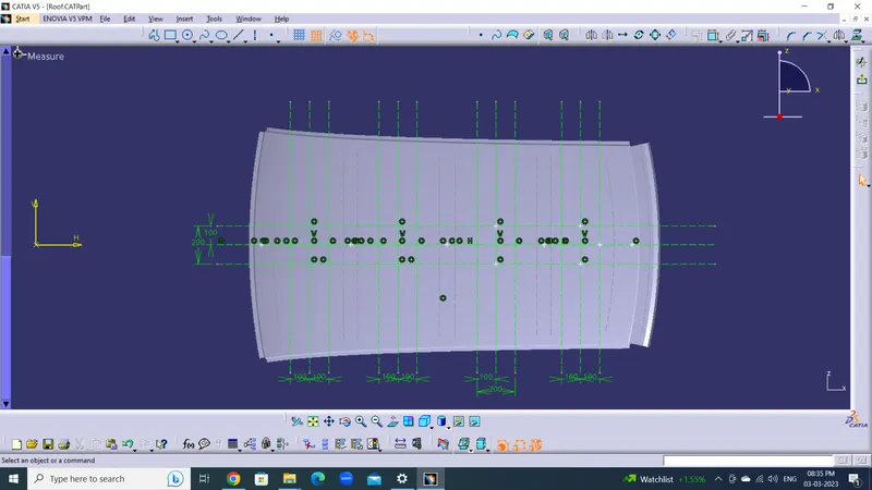
- Extract the required points and project them on the roof surface. Now using these points create a 3 point arc or circle and note the radius of the arc in the X direction as Rx">Rx and in the Y direction as Ry">Ry
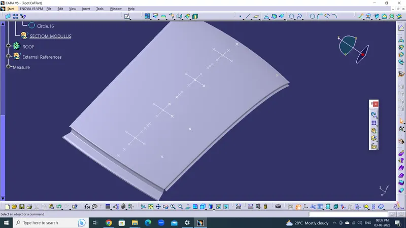
Now since we got all the values for calculating the Snow Load Criteria, substitute these values to the below equation.
Qr = [Iy x t2] / [α x s x [(Rx + Ry)/2]2 x 10-8]
| SNOW LOAD CRITERIA | ||||||||||||
| IY | α | LX | LY | Y | S | RX | RY | t | [(Rx+Ry)/2]^2 | Qr | RESULT | |
| FRR-BR1 | 1.782 | 1.027 | 1183.428 | 2023.44 | 472.625 | 489.367 | 4049.768 | 16137.18 | 0.75 | 101878227.5 | 19.769 | TRUE |
| BR1-CRR | 1.999 | 1.075 | 1183.428 | 2023.44 | 506.109 | 507.447 | 4272.692 | 11041.61 | 0.75 | 58631930.81 | 26.907 | TRUE |
| CRR-BR2 | 1.76 | 1.079 | 1183.428 | 2023.44 | 508.785 | 485.571 | 3763.747 | 6087.769 | 0.75 | 24263091.87 | 38.351 | TRUE |
| BR2-RRR | 1.011 | 1183.428 | 2023.44 | 462.357 | 2624.023 | 4514.278 | 0.75 | 12738835.29 | #DIV/0! | #DIV/0! | ||
RESULT:
The Snow load Qr < 3.80 result ok
https://drive.google.com/drive/folders/1WabrcZZHbm1NvAGVy8SOZs-iTnynsw4y?usp=share_link