Week 14 challenge
BUTTERFLY VLAVE
Project Objectives :
- Select Application (water, Gas, Chemical) of valve, Specify Pressure , Temperature & Enviornment conditions.
- Chose the in which Pipe size to fit butterfly valve, select material & apply properties.
- Create 3d Model of Components individually of Valve.
- Assemble the individual components with appropriate constraints with attach part to pat.
- Generate the GD&T Drafting of Componets for assemble and machining purpose.
- Create the Assemble drawing with Gd&t & Bill of material.
Software Used :
NX CAD 12.0
Introduction :
GD & T (Geometric Dimensioning & Tolerancing)
Geometric Dimensioning & Tolerancing is standard language for comunicate Engineers, Manufacturers. It is a symblolic language used in part drawings for assemble and mabufacturing. GD&T Sets Standard of system to define the part geometry, allowable verations.
History
- In 20th century early industrial revolution used traditionally dimension system.
- Stanley parker is the orgin of Gd&T, In 1938 he developed position(true position) tolerance.
- In second world war time he determine the importance of geometry tolerances.
- In 1960-70 The american society of mechanical engineers(ASME) introduced the Modern Gd&T ASME 14.5
- ISo(international standard of organization) alos control Gd&t called as Globel product specificarions from 1940.
Applications Of GD&T :
Gd&T used various industries the Componets fit together correctly.
- Aerospace : High precison and reliability for safery of crictical componets.
- Automotive : To maintain consistent of Quality of products in mass production.
- Medical : Guarantees the functionality and safety of intericate devices.
- Consumer electronics : parts fit together with minimal variation fo aeshetic and functional purpose.
Uses & benfits of Gd&t :
- Cost efficiency : Reduces the need of tight tolerace tha reduce Manufacuring Rework & Scrap.
- Communication : Provides a clear & concise way to describe GD&T requiremnets on drawing.
- Quality efficiency : To maintain Quality of produts.
- Interchangeability : Ensure the parts form different suppliers fitgether correctly.
Mastering Tools in Gd&T :
Gd&T uses Symbols & rules to define the allowable variations in part's geometry.Datums.Datums.
- Datums : Reference points, lines, area & Surfaces on part uses for assemble and staring poin to measuring.
- Feature Control Frame(FCF) : Used for apply geometric tolerances with used symbols & datums
- Geometric tolerances : Geometric tolerances are the symbol based apply for specific geometric characteristics.
Butterfly Valve:
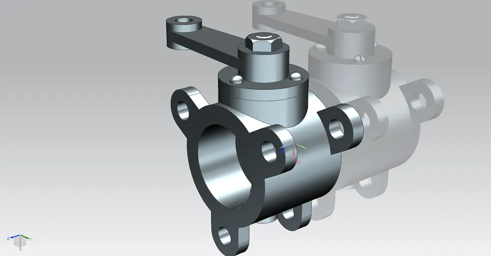
A Butterflyvalve is a Quarter-Turn valve used to regulate flow.The Operatin Of valve Fully closed & fully open upto 90°. it consists disc on rotating shaft. When disc complte closed the fluid flow Blocks, whem it open the fluid passing one way to other way.
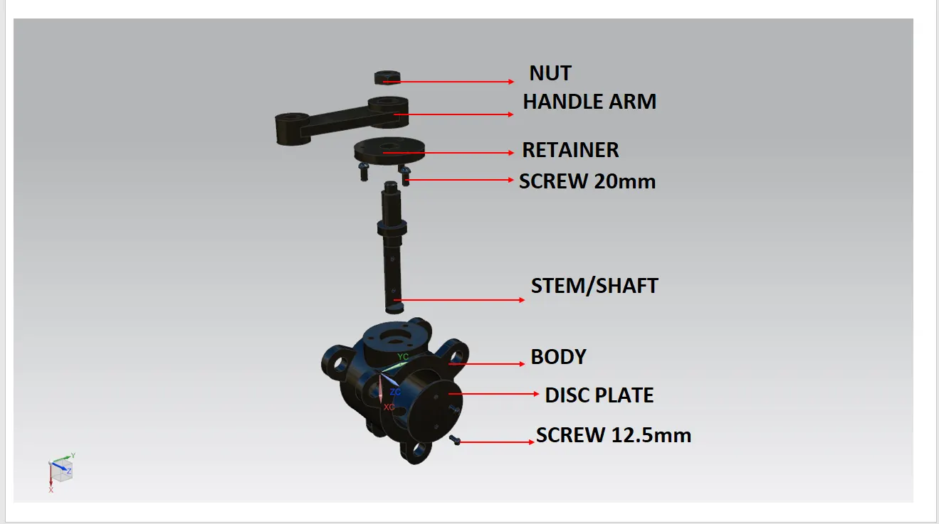
Components Of Butterfly Valve :
- Body
- Stem or shaft
- Retainer Plate
- Disc Plate
- Handle Arm
- Nut
- Screw
PROJECT SCOPE :
To Develop the Buttefly valve Assemble product in two ways
1. Top Down Approach - Components can create & Develop with in Assemble file.
2. Bottom up Approach - Componets can create & Develop individually.
Use Bottom up Approach Assemble for butterfly Valve. Sequence of
- 3D Component Design.
- Generate GD&T Drafting of Parts.
- Assemble the components
- Generate Assemble Drafting.
1. 3D Component Design :
First to create Componets of use Modelling module in NX Cad. to create components individully.
- To create the Body of butterfly Vlave open the modelling module in nx cad select units millmeter.
- Make the sketches Should be fully Constrained. Use only datum Plane for create sketchs
- Open Sketch Tab module to create of Sketchs for Body.
- To create Circle sketches of Body with fully constraine geometrically & Dimensionally
- Create the 3d model of Part from sketch use basic features Extrude, Revolve.
- Use Modify features to develop Component.
- After Creating Part save the files in folder.
a) Body :
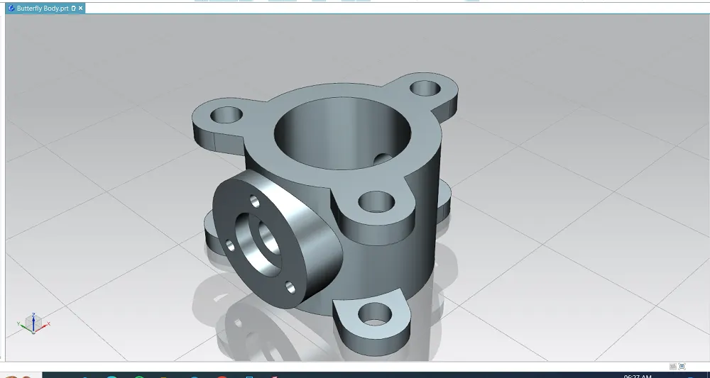
Body is main component in Butterfly valve to hold all other components. The body is also connect with the pipe.
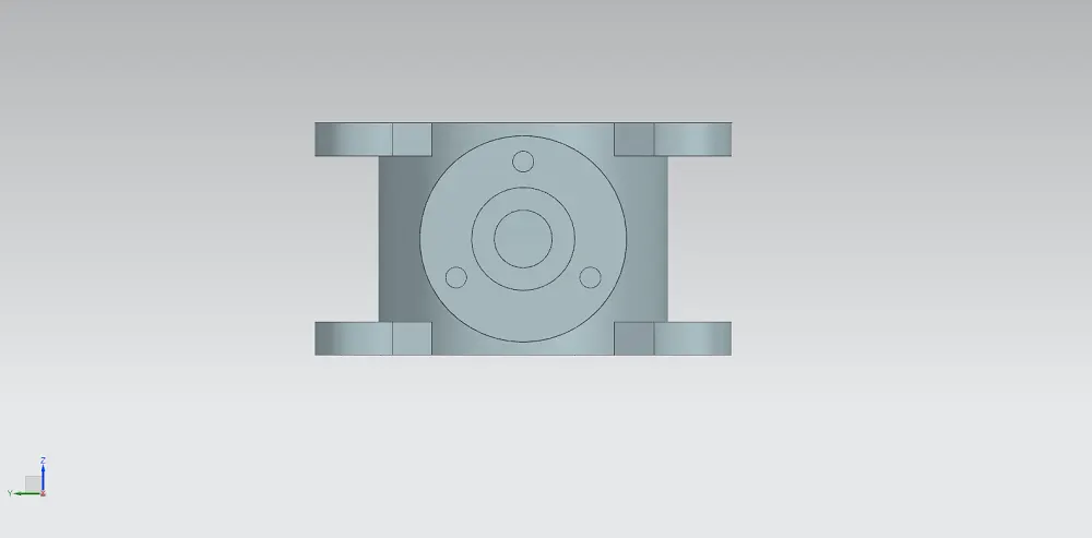
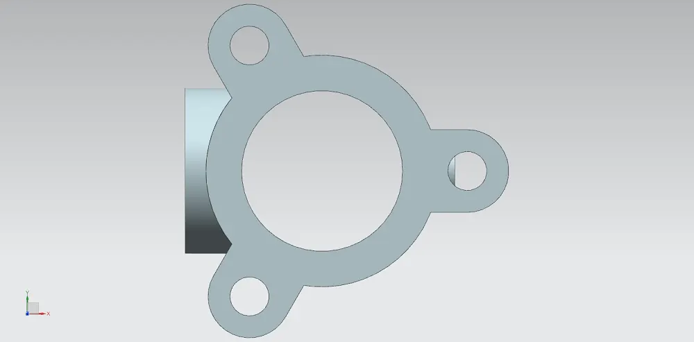
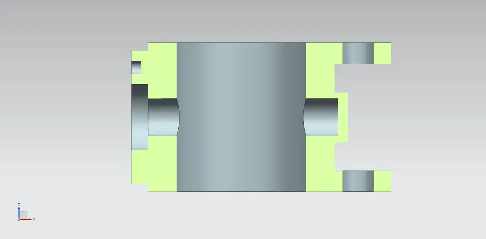
- The body had cylindericilly Outer dia Ø280mm Inner dia Ø194mm and height 255mm.
- Also 3 Connecting features circularlly with pipe.dia of hole Ø47mm outer profile R50 Connect with cylider surface from center 75mm Thickness of 32mm from both top sides.
- A Cylinder feature also Normal to cylinder circular face with 3 screw holes PCD 150mm dia of Ø20.30, main shaft hole also with Counter Hole main dia 56mm Deep 310mm Counter bore dia 100mm depth 25mm.
ISOMETRIC
FRONT VIEW
TOP VIEW
- SECTIONAL CUT SIDE VIEW
b) Shaft :
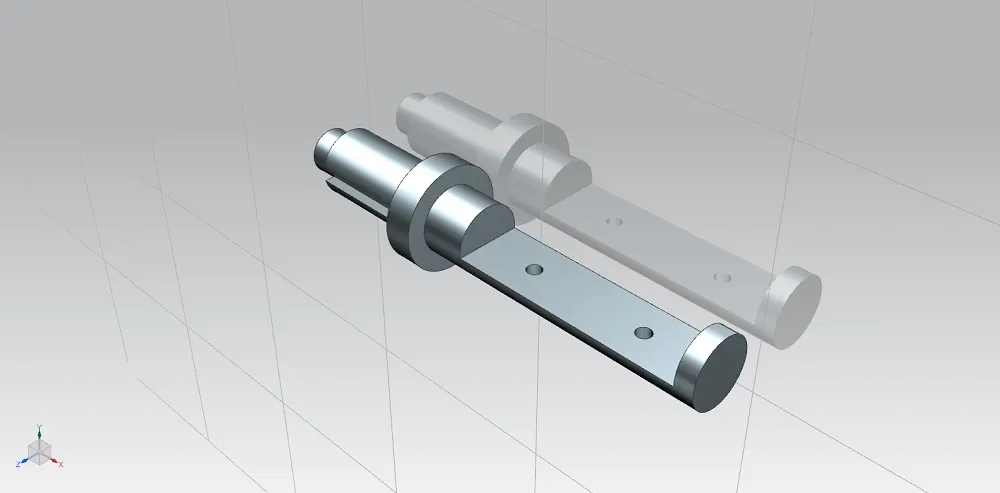
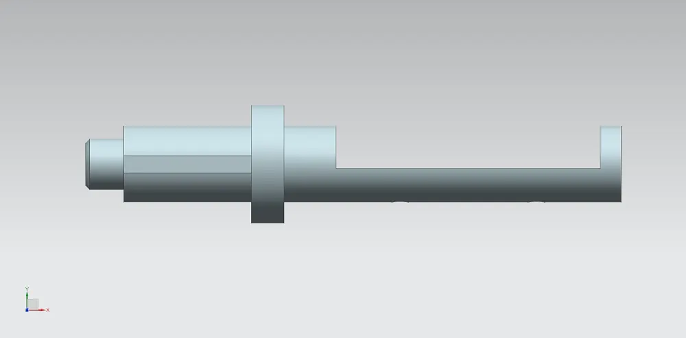
The shaft component in Butterfly valve to use open close Disc plate, the shaft connects Disc plate, Body, Handle arm, & nut.
- The shaft is circular part dimeters of to hold nut dia 37.50 mm length 28mm, Body Dia Ø56mm length 93.5mm, Flange dia Ø87 mm thickness 24mm, and body dia Ø56mm length 247.1mm.
- A flate surface for mountaing the Disc plate normal to Body circular face Length of 193.8mm Height of 31.1mm from Vertically cylindercal edge Position from horizontally 38.2mm from the flange edge. also 2 Screw holes dia Ø12.50mm dia distance 100mm linearly position from centerly in axis & 62mm body edge.
- Akey cut use lock the Hadle & shaft with of 12.6mm Length 93.50 aplly face depth of cut 18mm
ISO METRIC VIEW
FRONT VIEW
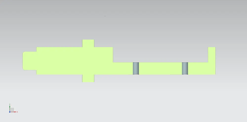 SECTIONAL CUT FRONT VIEW
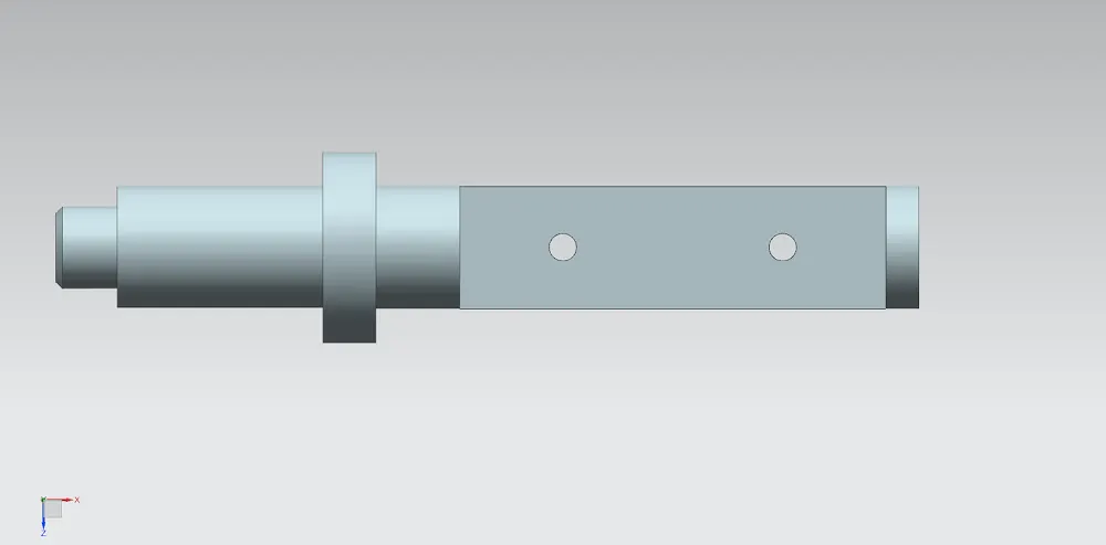
TOP VIEW
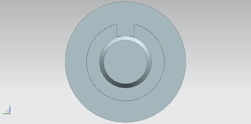
SIDE VIEW
c) Retainer :
The Retainer plate used in Valve to reduce thr Leakage the of fluid , the Retainer plate Mountaed on the body face lpcked with screws.
- The Retainer plate Circularly dimeters Ø200mm Outer Ø56mm Shaft hole Diameter thickness of plate 25mm.
- Three Screw Holes Placed on Plate diamter Ø20.30, Position of screw holes PCD150mm from center.
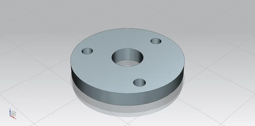
ISO METRIC VIEW
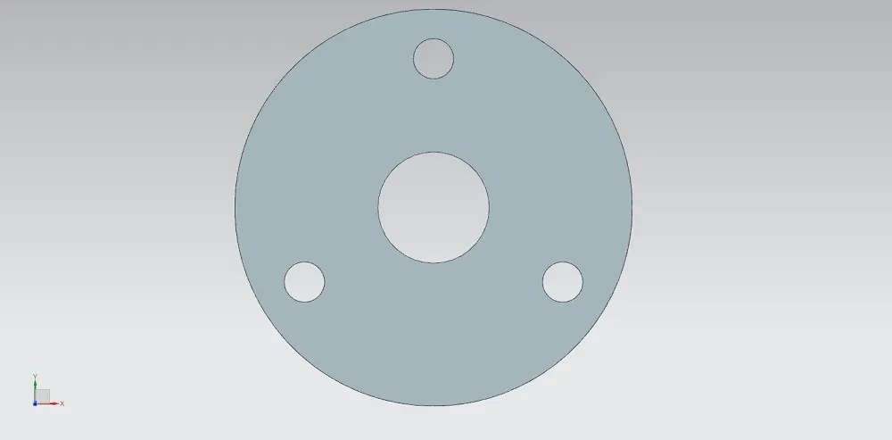
TOP VIEW
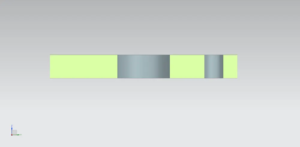
SECTIONAL CUT SIDE VIEW
d) Disc Plate :
The Disc plate use to close & open the fluid flow In butterfly Valve , The Disc is Placed on the Steam/shaft flat surface are lock with screws.
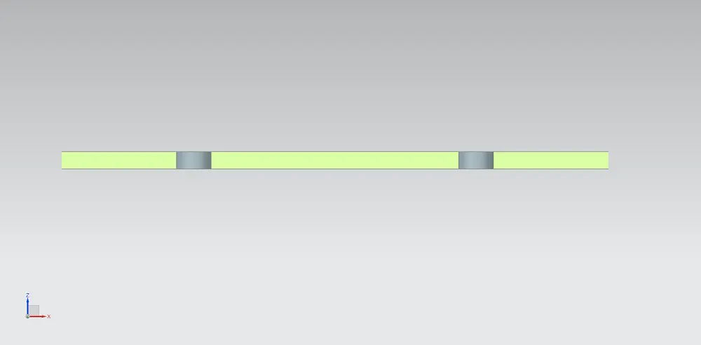
- The Disc plate Eliptically dimeters Ø205mm Major dia Ø193.80mm Minor Diameter thickness of plate 6mm.
- 2 Screw Holes Placed on Plate diamter Ø12.50, Position of screw holes 100mm from centerof two holes both side symmetrically from center .
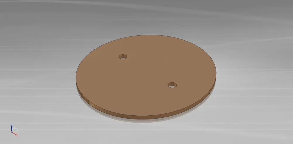
ISO METRIC VIEW
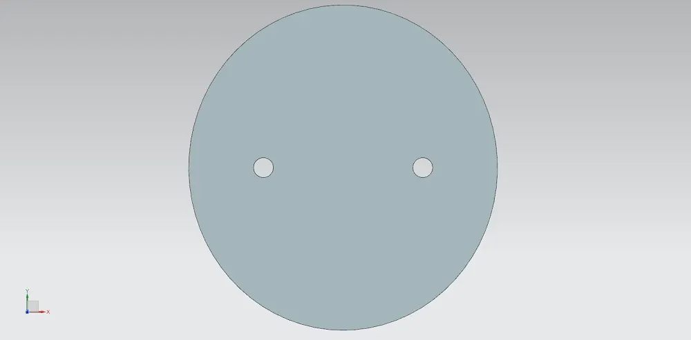
TOP VIEW
SECTIONAL CUT FRONT VIEW
e) Hadle Arm:
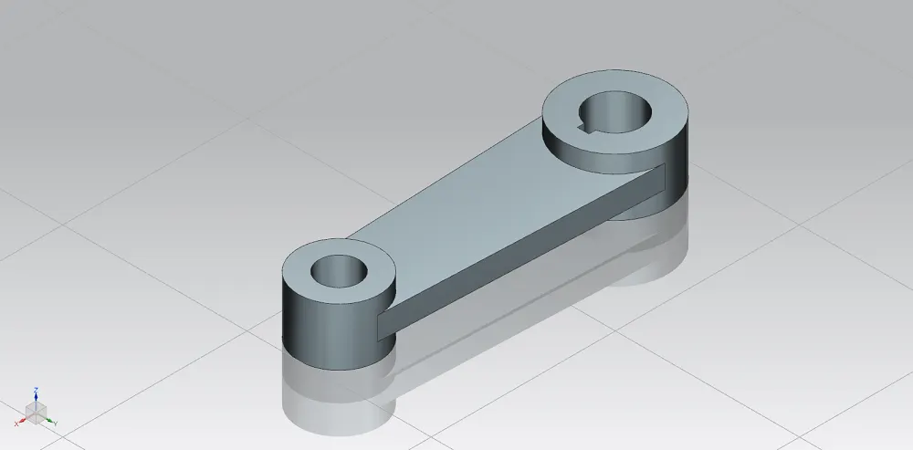
The Handle is to use for rotate the shaft to open or close the discplate of control the fluid flow In butterfly Valve , The Hadle arm assembled on shaft alog with key to avoid the slip the rotations, locke with Nut.
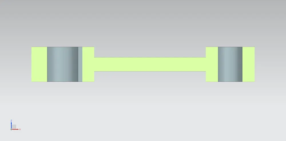
- Handle arm has a two cylindricale walls connected with milldle wall
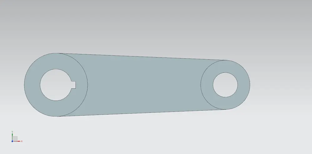
- Cylindercal wall Outer dia Ø112.50mm Shaft hole dia Ø56.3mm with key way 12.6 width 35mm distance from center thickeness of 62.50mm.
- Other cylider wall help hold rotating purpose Diameters of Ø87.50mm Outer & 43.8mm inner hole dia thickness of 62.5mm position from cylinder 300mm.
- A middle wal connects the cylinder walls thickness of 25mm symetrically devide both sides.
ISO METRIC VIEW
SECTIONAL CUT FRONT VIEW
TOP VIEW
f) Nut:
The nut assembled the Shaft mounted on face handle face . To use nut lock the hadle with stem.
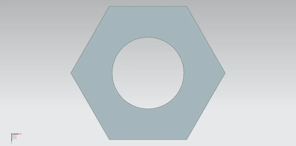
- A hexgonNut size 69mm width hole dia 37mm thickness of 25mm
- R10mm Corner radius.
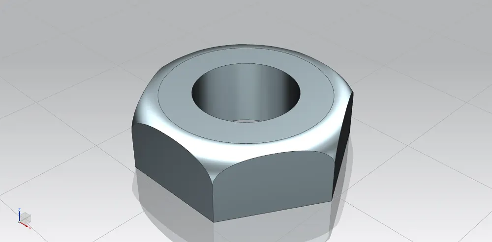
ISO METRIC VIEW
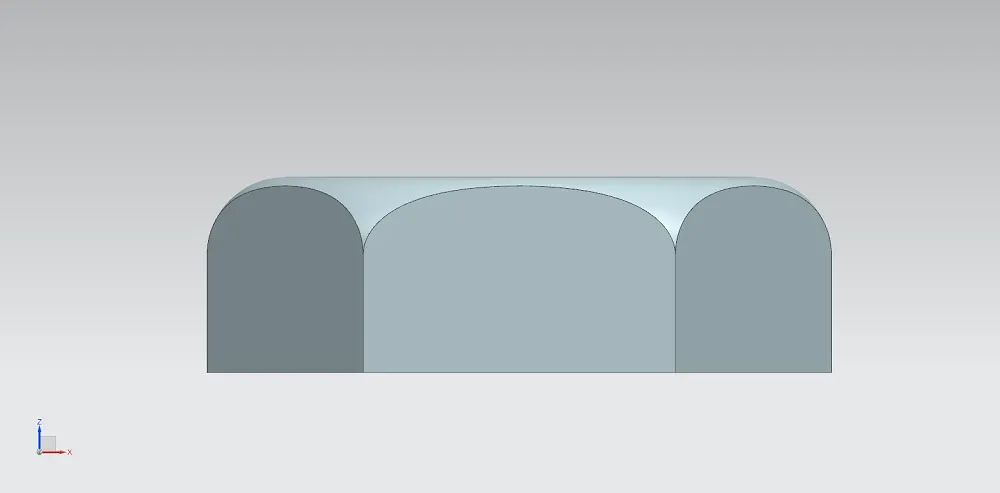
FRONT VIEW
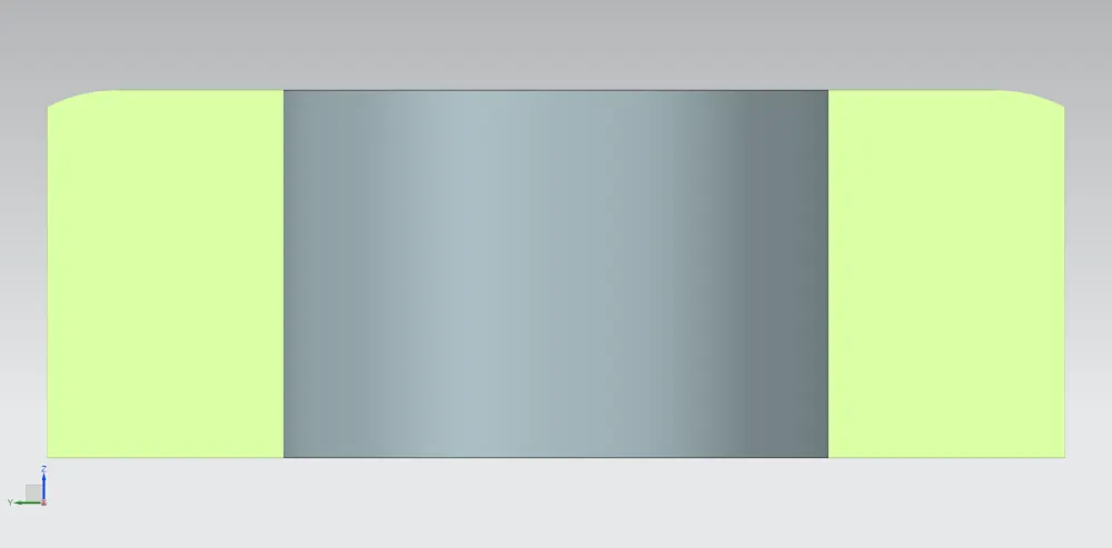
SECTIONAL CUT SIDE VIEW
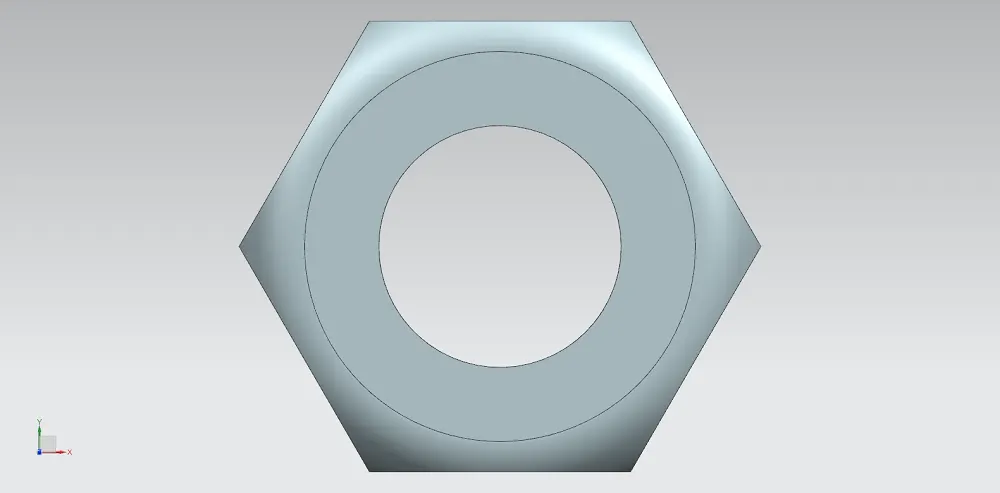
TOP VIEW
BOTTOM VIEW
g) Screws:
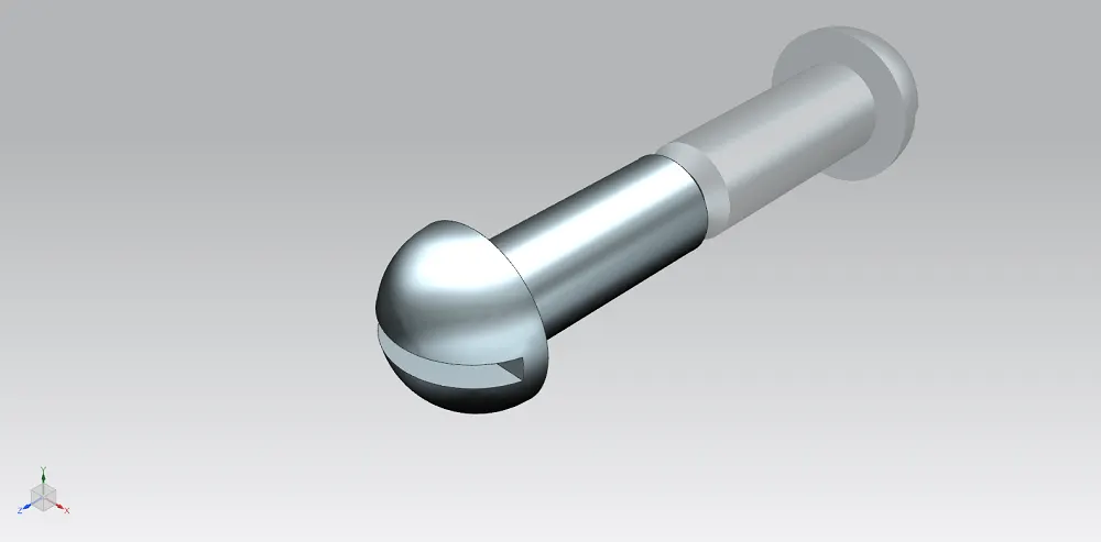
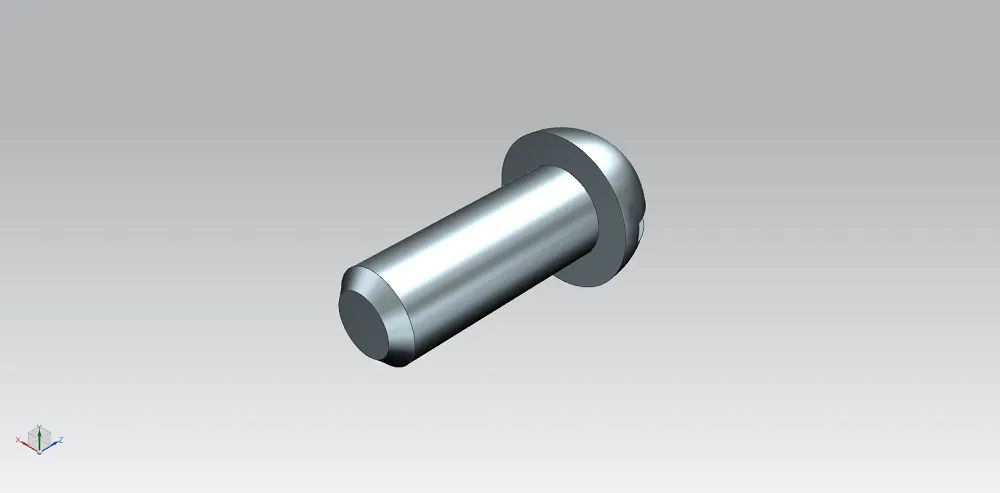
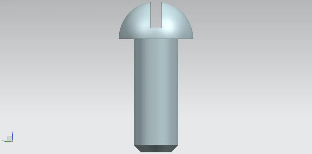
The screws are functionally assemble to lock the retatineerplate with body. and 12.5mm screws are lock the disc plate with stem.
- A screw shape round bodydia Ø20mm Sphere head 30mm dia with slot 3mm gap on center with entry chamfer.
- other screw round body dia Ø12.5mm sphere head 21mm dia with slot 3mm gap on center.
ISO METRIC VIEW - FRONT
ISO METRIC VIEW - BACK
TOP VIEW
2) Generate GD&T Drafting of Parts.
Create the drafting of components individually its guide to machining & Assemble the parts to other parts which lock the six degrees of freedom.
- Generate Drafting of components.
- Select approrate sheet size for the parts.
- Generate the diamensions of parts with respect to tolerance.
- Create datums or datum targets for assemble guide referance.
- create the required GD &T tolerances of components.
a) Body :
The Body is a is a basic component in butterfly valve. The Gd&t of Body component
- The Primary Datum of body is represented on surface main cylyder face which is connect to pipe & its represnted as datum targets A1, A2 & A3 Circular Areas Ø40mm.
- A flateness tolerance to control to applied on surface 0.25.
- The secondary datum is Hole of any on to lockate the position Dtum B.
- A perpendicular 0.15 with MMC tolerance to appied on hole referance to datum A along projected tolerace 225
- Position tolerance of Hole 0.10 with MMC applied referance of Datum A Datum B with MMB along projected tolerace 225
- The tertiary datum located at other hole Datum C.
- A positon tolerance screw Hole 0.10 with MMC referance of Datu A , B & C. The B & C are functionally MMB.
- A positon tolerance Main Hole 0.10 with MMC referance of Datu A , B & C. The B & C are functionally MMB
- A Profile tolerance 0.10 referance datum A, B & C
- To create antoher datum D which is retaine connectin the body areas represented with Datum targets D1, D2 & D3 are circularrly Ø40
- The secondary datum for Retainer plate is Hole of any on to lockate the position Dtum E.
- A perpendicular 0.15 with MMC tolerance to appied on hole referance to datum D
- Position tolerance of Hole 0.10 with MMC applied referance of Datum D Datum E with MMB
- The tertiary datum for retainer plate located at other hole Datum F.
- A positon tolerance screw Hole 0.10 with MMC referance of Datu D, E & F. The B & C are functionally MMB.
- A positon tolerance Main Hole 0.10 with MMC referance of Datu D , E & F. The B & C are functionally MMB
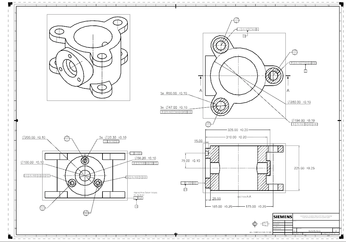
BODY GD&T DRAFTING
b) shaft :
The Shaft has rotating part in butterfly valve.
- Flatness of surface 0.25 which shaft base connect the surface of body face.
- The Primary Datum of Shaft is represented on surface Circular face Datum A1 & A2.
- The secondary datum on to lockate the flate Faace datum B
- AComposite position tolerance of screw hole 0.25 of PLTZF referance datum A & B & 0.10 of FRTZF Datum A.
- Position tolerance of Key way 0.20 referance datum A Datum B.
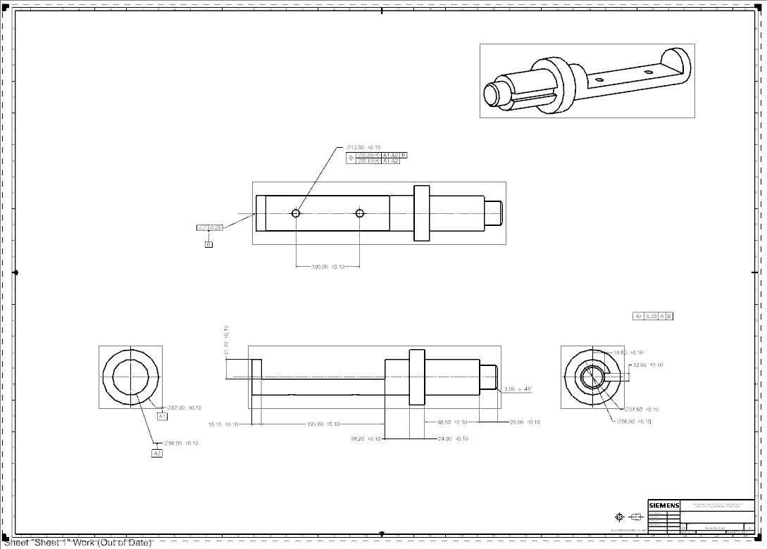
SHAFT GD&T DRAFTING
c) Retainer Plate :
- A Flatness of surface of retainer plate 0.20
- Datum of Retainer plate is represented on surfaces circularly datum targets A1, A2 & A3 Circular Areas Ø40mm.
- A Profile of surface 0.20 with referance datum A.
- A perpendicular 0.15 with MMC tolerance to appied on hole referance to datum A
- The secondary datum is Hole of any on to lockate the position Dtum B.
- Position tolerance of Hole 0.40 with MMC applied referance of Datum A Datum B with MMB.
- The tertiary datum located at other hole Datum C.
- A positon tolerance screw Hole 0.40 with MMC referance of Datu A , B & C. The B & C are functionally MMB.
- A positon tolerance Main Hole 0.40 with MMC referance of Datu A , B & C. The B & C are functionally MMB.
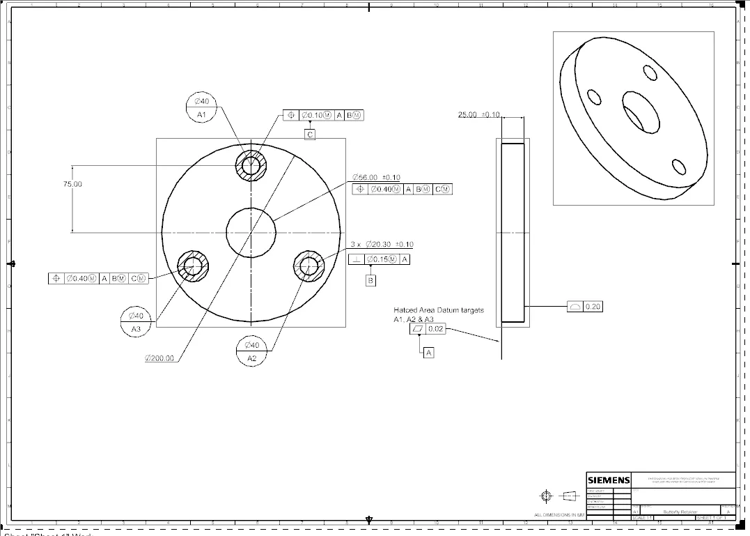
RETAINER GD&T DRAFTING
d) Disc Plate :
- A disc plate sufrface mount with shaft flatness tolerance 0.20
- The datum targets area Ø30 of A1, A2 of primary datum.
- A Profile of surface 0.20 with referance datum A.
- A perpendicular 0.10 with MMC tolerance to hole referance to datum A
- The secondary datum B placed on Circular hole.
- Position tolerance of Hole 0.10 with MMC applied referance of Datum A Datum B with MMB.
- The tertiary datum located at other hole Datum C.
- A positon tolerance screw Hole 0.10 with MMC referance of Datu A , B & C. The B & C are functionally MMB.
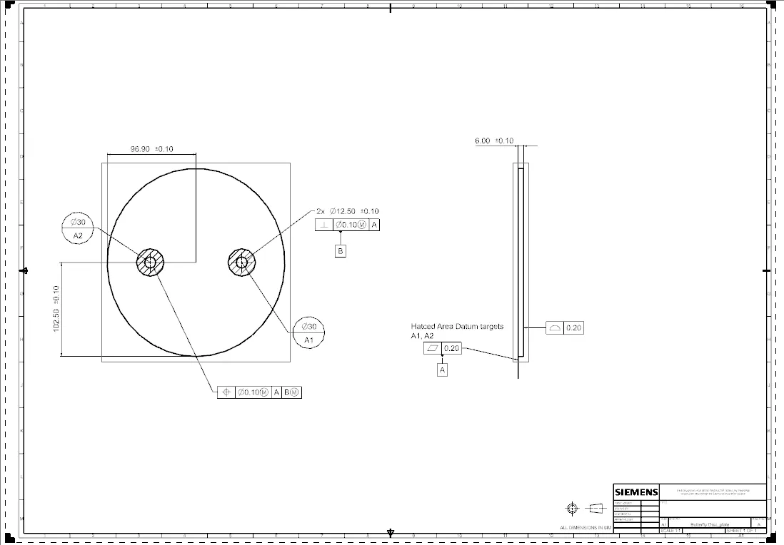
DISC GD&T DRAFTING
e ) Handle Arm :
- A Handle arm sufrface flateness tolerance 0.10 mount with retainer face
- The primary datum A on face
- A perpendiculartolerace of shaft hole 0.20with MMC referance datum A.
- The secondary datum B placed on Circular hole.
- Position tolerance of keyway 0.15 with MMC referance of Datum A Datum B.
- The tertiary datum C in the Keyway surface with compltly locck with handle.
- A positon tolerance Hole 0.25 with MMC referance of Datu A , B & C. The B & C are functionally MMB.
- A Profile of surface 0.20 with referance datum A. of all other cylinder faces.
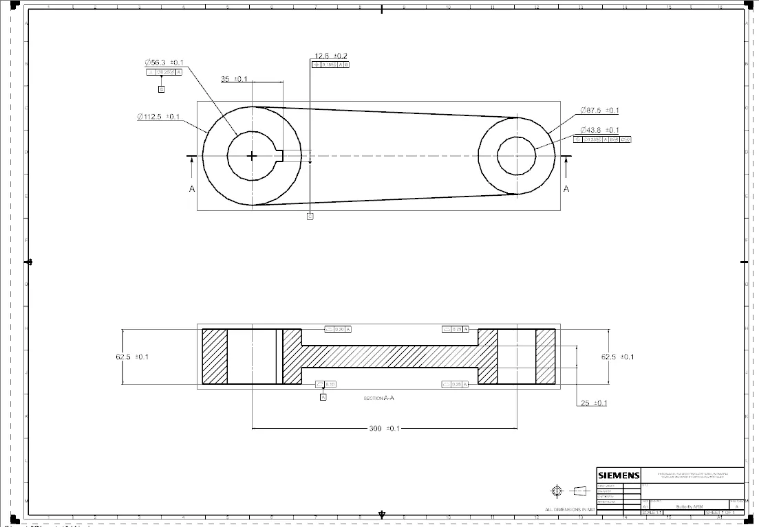
HANDLE GD&T DRAFTING
f ) Nut :
- The priamary datum A of nut on face mount on the shaft.
- the perpendicular tolerance of Nut hole 0.25 with MMC referance datum A.
- the secondary datum B of nut is place on the circular hole.
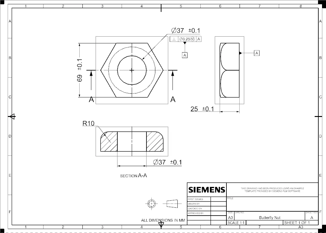
NUT GD&T DRAFTING
g ) Nut :
- The priamary datum A of screw on circlar face of screw body face touch with hole circular face.
- the secondary datum B of screw on bottom face of head touch with part flat face.
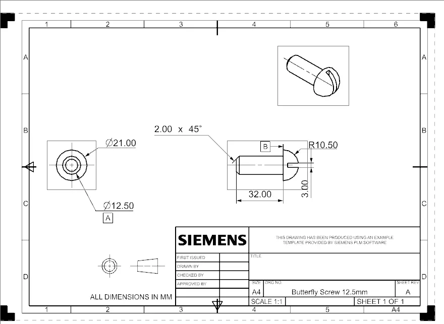
SCREW GD&T DRAFTING
3) ASSEMBLE THE COMPONENTS :
Assemble the components of Butterfly valve Individually. use assembly constraints for make Assemble relations between componnets. The butterfly valve has one free moment of of rotation to opwn & close the disc plate to control fluid flow.
The assemble sequience for adding & assemble the components of butterfly valve.
- Open asse,ble file add component of main component of butterfly valve.
- Add body Component in assemble file place corrcet location & orientation direction on assemble use move componen command.
- Use Fix command in Assemble constraints for fix the Body part in assemble to Lock all Six Degrees of freedom.
- Add Shaft/Stem part in butterfly assemble, move & orientation the part place nearly to body componet.
- Use Inffer Center axis Constrain in assemble constraints for connect to body in side cylinder face center axis to stem center axis of stem part location.
- use Touch or distance constrain for of fat face of stem and side face body to lock translation motion on butterfly valve.
- No need lock rotation constrain for lock the stem will rotate to open & close control fluid flow.
- Add Disc plate component use move command for place extly near to stem flat face.
- Select flat face on stem on cut area & surface of Disc plate use touch constrain of selected faces to lock one translation two rotations of disc plate.
- To lock two translations & one rotation of Disc plate select the screw holes axises of stem & disc plate use Infer center axis.
- Add 12.50mmScrew componet use Align lock constrain for screws to lock rotation on individual axis & two rotations & two translation of screw with stem & discplate.
- Select the touch face constrain on face screw head bottom face & disc plate face to lock completly.
- Add the Retainer plate on assemble, Select Infer center constrain of Body Side center circular axis & Retainer center circular hole center axis to lock two translations & two rotations of retainer plate.
- Select Infer center axis of screw hole & body screw hole to lock rotation on own axis.
- Use Touch constrain in assemble constarin of select face of Body side face & retainer plate face to lock translation of retainer plate completly with body.
- Add 20mm Screw componet use Align lock constrain for screws to lock rotation on individual axis & two rotations & two translation of screw with Body & retainer plate.
- Select the touch face constrain on face screw head bottom face & retainer plate face to lock completly.
- Use circular pattern of aplly screws add circularly.
- Add the Handle arm component in assemble, Use the infer center axis constrain in assemble constraints select the center axis of stem & center axis of hadle hole to lock two ratations & two translations of handle.
- Select the faces of hande cyliner profile face & retainer face apply touch constrain on assemble constriants to attach handle on face & lock one trsnslation degree.
- Select the two side faces of keyway cut on hadle & stem apply 2 of 2 center constrain to lock completly.
- Add nut to assemble, use Align lock constrain for Nut to lock rotation on individual axis & two rotations & two translation of nut with stem.
- Use Touch Constrain select the faces of Nut & Handle arm.
The Compomets assemble completly. there only One roation degress of is only unlock to control fluid flow.
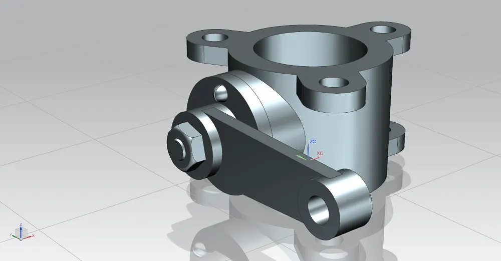
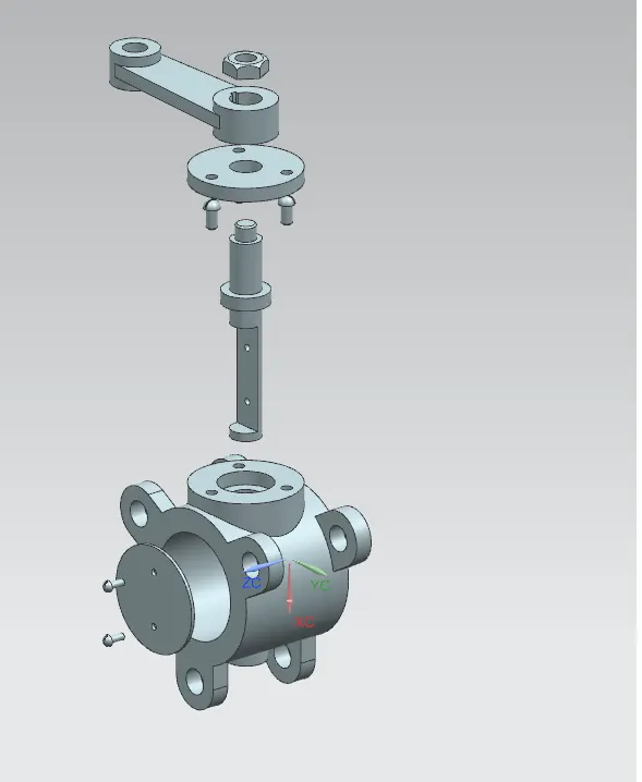
4) Generate Assemble Drafting :
Assembly Drafting is a process creating technical drawings that how Individual components are used in assemble & sequence. This is a crucial phase in the design and manufacturing process, ensuring that all components work harmoniously in the final product.
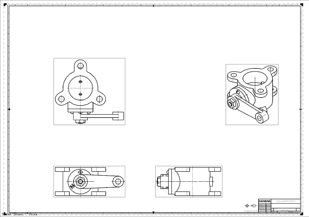
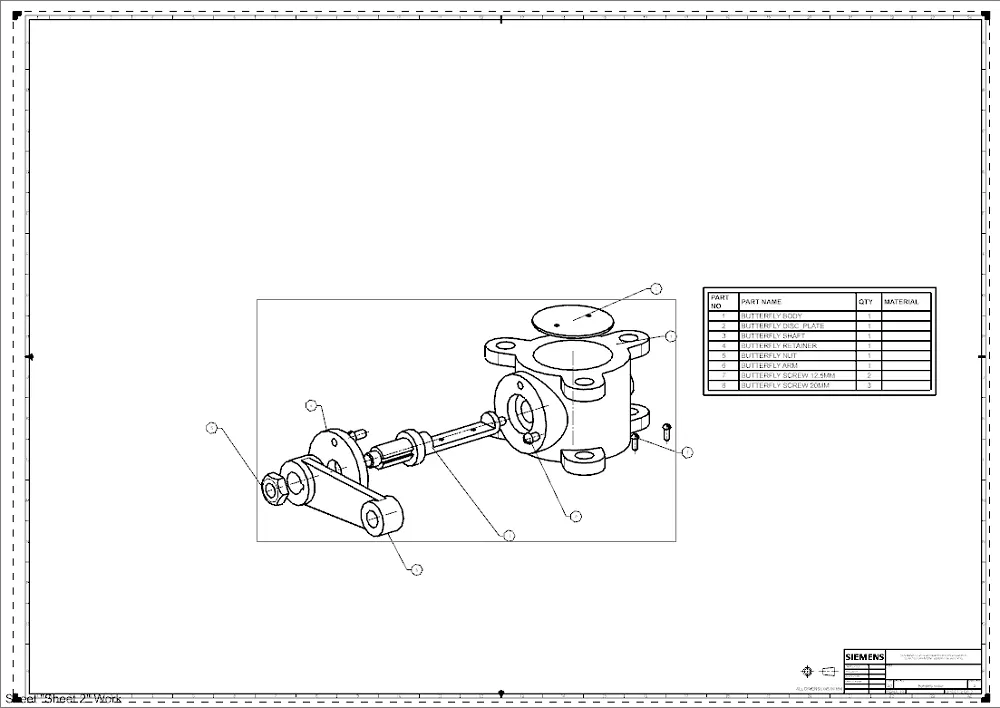
The Process of assemble drafting. The assemble drafting generate in multiple sheets Views & exploded views & gd&t apply to individuall sheets.
- Select the sheet size A1 of apply assemble drafting.
- Add Bsic views Front view, top view, Side views & is metric view of Burtterfly valve Assemble in drafting sheet No-1
- Add new sheet in assemble drafting & select the sheet A1.
- Add Exploded view of butterfly valve assemble in assemble sheet.
- Apply table of Bill Of material in Assemble that will guide what componets name, Material, Description & Quantity of assemble.
- Apply Boolean Number of assembly the will show which part number & component in Bill of materil.
- Add new Sheet, Select proper Sheet size.
- Add Basic Views of of butterfly valve assemble Front view side vies, sectional views.
- A flateness tolerance to control to applied on surface 0.25.
- The Primary Datuam of Assemble represnted as datum targets A1, A2 & A3 Circular Areas Ø40mm which connect to pipe.
- A Profile tolerance 0.25 referance datum A on oppisite face.
- The secondary datum is Hole of any on to lockate the position Dtum B.
- A perpendicular 0.15 with MMC tolerance to appied on hole referance to datum A.
- Position tolerance of Hole 0.10 with MMC applied referance of Datum A Datum B with MMB.
- The tertiary datum located at other hole Datum C.
- A positon tolerance screw Hole 0.10 with MMC referance of Datu A , B & C. The B & C are functionally MMB.
- Add Datum D on On hole that is referance opposite face.
- Add Positon Tolerance on 0.25 on opposite holes which connect other side pipe represent datum B,C, & D individually.
CONLUSION :
Butterfly valve Assembly drafting in N CAD is a vital component of the design and manufacturing process. It ensures that all parts fit together seamlessly and function correctly within the final product. By leveraging advanced CAD tools and techniques, engineers can create accurate, detailed, and easily understandable assembly drafts that streamline the production process and enhance product quality.