Week 9 - Attachment Feature Creation (Ribs & Screw Boss) - Challenge 1
Attachment Feature Creation (Ribs & Screw Boss)
AIM:
To be able to Create the Door Handle Component from the given Class-A surface.Create the tooling axis for the given Class-A Surface meeting the requirements of the draft angle. to ctreate a Rib and Screw boss.
DESCRPTION:
ATTACHMENT FEATURE:
Attaachment feature are B-siside Features. which help fitting and improve strength with out increase material thickness. avoid the shink marks on the part wile manufacturing.
RIB :
Rib is a Attachment to increase strength off wall with out increase wall thickness.Ribs are thin wall-like structures that add support and rigidity to injection molded parts.
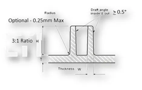
For the design of rib we can follow rules that are
SCREW BOSS :
A boss is a cylindrical protrusion placed on a part’s wall. A boss can have various functions, such as the following:
- Positioning aid – To help align parts during assembly; for example, a pin on one part will fit a hole in the other part.
- Fixation point – In the example mentioned above, the pin and hole can have a press fit. Friction between the two keeps the parts fixed. A boss can also be a tubular protrusion that can accommodate self-tapping screws to fix other parts.
- Bearing surface – A cylindrical protrusion can act as a bearing for another part; for example, a lever or a gear to rotate about.
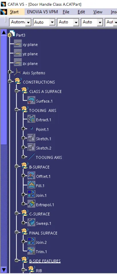
1.CLASS A SURFACE:
Define and verify Calss a surface. surface is closed are not any open boundarys are there.
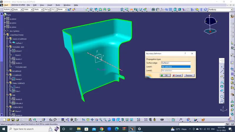
2. TOOLING AXIS :
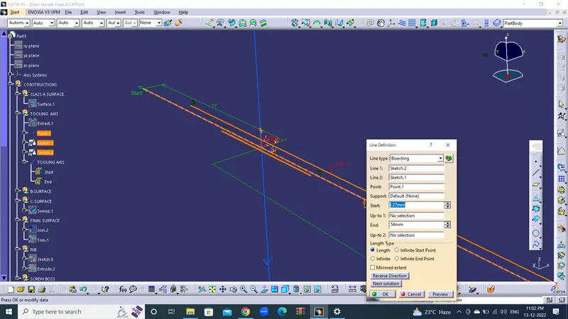
The Tooling Direction is basically the direction that the mold pulls a part. The mold is built in two separate pieces, basically. You have a Cavity side and you have the Core side. The Core pulls apart from the Cavity and that's the Mold line or the Tooling
To create TOOLING Axis use the bisecting method. create the Line in positioned sketh YZ axis plane. and create lene in xy plane in positioned sketch. and create Tooling axis bisecting method .
3. B-SURFACE :
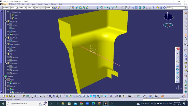
To create B-SURFACE offset the CLASS A SURFACE 2.5mm insde. Add the missing surfaces in B-surface which are in in the Class A Surfacce with using the sweep, Multi surface, Blend, join, fillet, split, trim and offset etc. Extrapolate all edge the surface 5mm so cna avode the gap.
Verify the B-SURFACE no gap marks in the surface.
4. C-SURFACE :
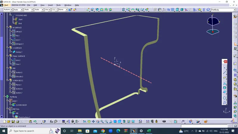
To create the C-surface use CLASS A SURFACE Outer Edge with Sweep feature along line command referance of class A surface 3° angel outer.
5. FINAL SURFACE:
Join the CLASS A SURFACE wirh C-Surface and Finally Trim with B-surface.
Verify the all Boundary are closed are not.
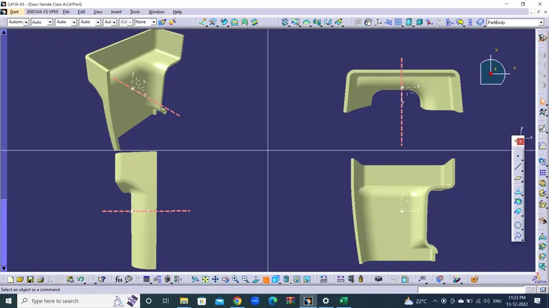
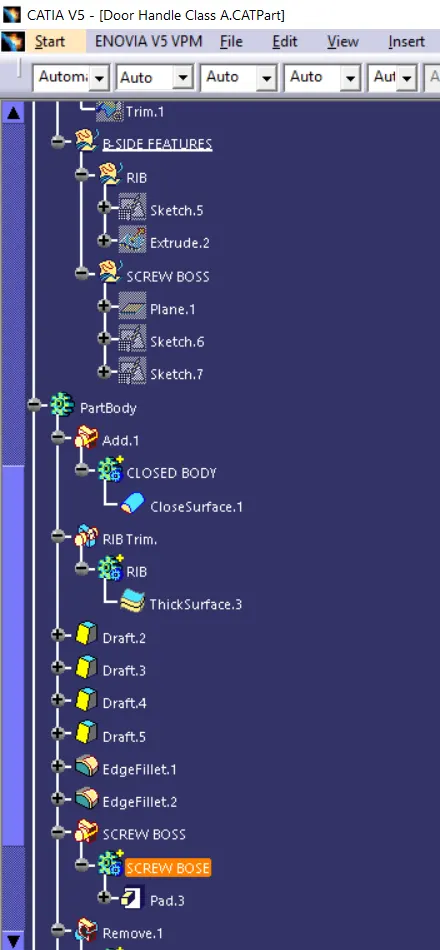
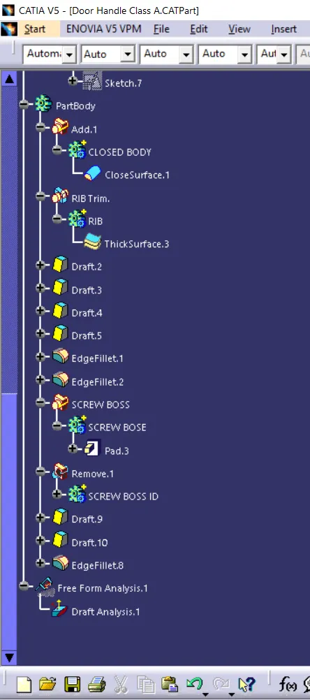
6. PART BODY:
Create solid Model from Closed surface. and add the part body in the main body solid feature
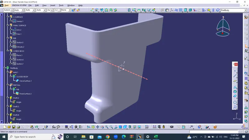
7. B-side Features :
RIB :
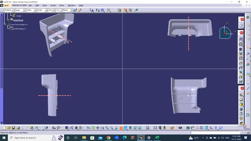
To create rib feature in model select the line and draw where you want it. Extrude the line surface height 3 times to theckness.
thick the surface and later Draft ≥ 0.50° all sides. finally give Edge Fillete 0.25 mm.
Add rhe Rib in main body
SCREW BOSS :
To create a Screw Boss wall thick ness must be 1.5 mm of screw hole diameter. height ≤ 5 times of wall thick ness and draft angle ≥ 0.50° in out.edge fillete 0.25 mm add the body in main body.
DRAFT ANALYSIS :
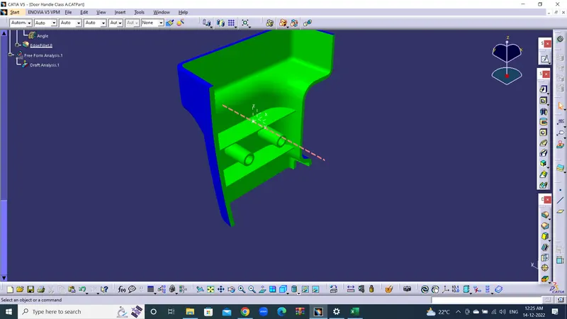
The Draft Analysis command enables you to detect if the part you drafted will be easily removed. This type of analysis is performed based on color ranges identifying zones on the analyzed element where the deviation from the draft direction at any point, corresponds to specified values.
To perform draft analysis select advanced Draft analysis select the tooling axis.
TREE STRUCTURE :