Project 2
BACK DOOR WIRING
AIM :
- Create Wiring Harness Routing for given Back Door.
- Application of all Packaging rules.
- Apply Protection coverings as required.
DESCRIPTION :
WIRING HARNESS :
Automotive wiring harness is defined as an assembly of wires, terminals, and connectors that run throughout the vehicle to transmit information and electric power. Automotive wire harness is designed according to electrical & dimensional requirement of automobiles and is integrated to connect different parts of vehicle such as body, engine, dashboard, chassis, and others. Automotive wiring harness enables transmission of control signals and electrical power to electronic & electrical devices in an automotive to ensure basic functionality & enhanced safety.
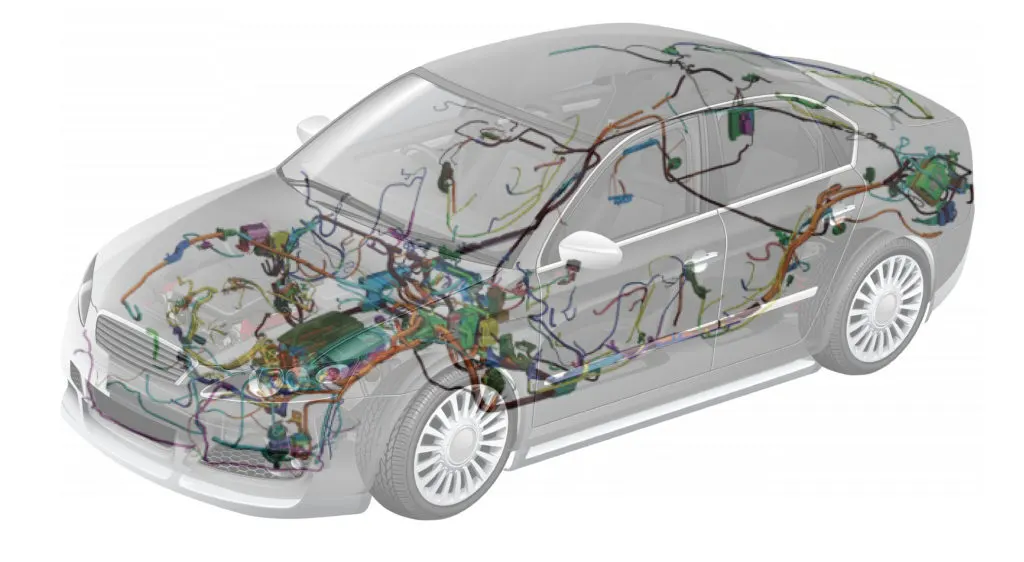
A wiring harness is an organized set of wires, terminals and connectors that run throughout the entire vehicle and relay information and electric power, thereby playing a critical role in “connecting” a variety of components. Power and information travel through this network much like the circulatory and central nervous systems of the human body.
As cars continue to provide advanced functions, their component parts increasingly require electronics to save space and meet other requirements. Experts at efficient design and configuring complex circuits, SEWS creates wiring harnesses that contribute tremendously to the development and advancement of car manufacturers around the world.
PACKAGING RULES:
RPC Electronics was contracted to manufacture this custom wire harness system for an OEM packaging equipment manufacturer. Working from 2D drawings and customer specifications, 6 AWG to 28 AWG wire sets were utilized for this assembly, along with the appropriate color-coded terminal and connector components. The wires were cut and stripped to prepare for mounting, and terminated according to requirements. The cables were wire marked for branding, and a series of in-process and post production testing was carried out to ensure customer requirements were met including testing for point to point continuity, and utilizing custom functional test fixtures.
- Wiring harness routing shall provide ease in manufacturing, accessibility, easy removal, and easy maintenance of attached equipment and wiring harness.
- Routing through small structural holes and openings shall be avoided, minimize chaffing and handling of the wiring harness during installation.
- Avoid the harness routing and clipping in the Blind zone of the Operator during harness assembly or in service.
- Routing shall offer protection against possible damage through common misuses such as being handhold and temporary support for test equipment.
- Provide additional slack to the harness according to the surroundings and harness bending requirements.
- Ensure the routing meets the clearance requirements with different surrounding parts.
- Avoid routing over the bolts, near to the bolted joints. It may damage the harness or puncture the harness. Keep harness away from panel mounting screws.
- Avoid harness routing near sharp edges, if not possible provide protection to the harness.
- The maximum distance between two clips on a straight branch is 200mm.
- Provide Clips and clamps if the harness is going to bend at multiple locations.
- The use of too many sheet-metal brackets should be avoided.
- The branch length should be more than 50 mm.
- Min distance between clip and branching point to be 25 mm.
- Min distance between two branch breakouts should be 50 mm
BACK DOOR WIRING HARNESS :
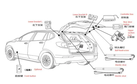
Car Back Door Electrical parts Rear Light, Parking Sensor, Brake Light, Number Plate Light, Wiper arm, Lock system.
Back Door Wiring harness Closed in automotive.
 .
.
BACK DOOR:
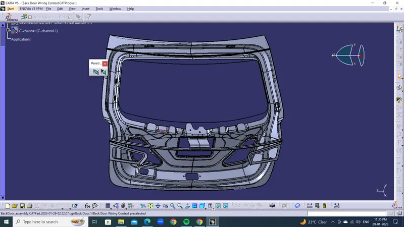
PROCEDURE:
1. Create Context File
2. Develop Geomentrical parts
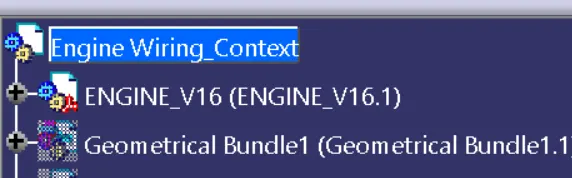
1. Create Maste File :
Create a master product file(Engine Wiring_Context) and two sub-level product files named Geometrical Bundle & ENGINE FILE respectively.
2. Develop Geometrical Bundle :
1. Define All Parts are Electrically.
2. Connectors Positioning.
3. Bundle Creation.
4. Protection Covering.
(A) PROCEDURE FOR CONNECTOR DEFINE A ELECTRICAL PART CATIA V5 :
- Create Geometrical Parameters.
- Define Part as Connector.
- Define Bundle Connection piont.
- Define Connector Connection point.
- Define Cavity Connection point.
1. Create Geometrical parameters :
1. Create a point on face Bundle entry area represent name as bundle connectionpoint.
2. Create a point on face Connector meating side represent Name Connector Connection point.
3. Create a Connector Connection axis referance of point which Connector connection point.
Note : In axis system The Y-Axis should be Meating direction and X-Axis Should be Locking position.
2. Define Part as Connector :
After Create geometrical parameters file change into the Electrical part design.
1. Define Part as Connector select the Define connector option in Electrical Device Defination tool bar.
2. In Connector definitaion Type should be Single insert Connector, part name as per requirement and number of terminations are how many Bundle placed in the connecto thea number .
3. Define Bundle Connection Point:
1. Select the Bundle Connection point in the Electrical connection point definition tool bar.
2. Representation and intial condition is the face which is Bundle entry and point is the Bundle connection point
4. Define Connector Connection point :
1. Select the define connector connection point in the Electrical connection point definition tool bar.
2. Representation is Connector Connectio point Contact is Face which Meating at connecton Coincidence is the Y-Axis Meatining direction and Orientation is the X-axis Locking position.
CONNECTORS USED :
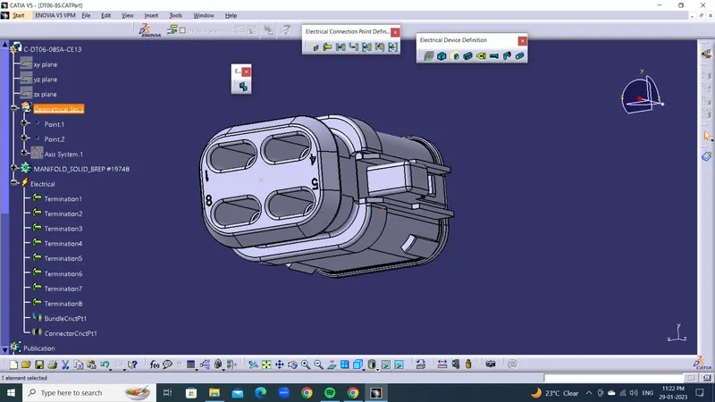
1) PART CODE : C-DT-06-8SA-CE-13
QTY : 1 No
No. Of. Terminations : 8 No's
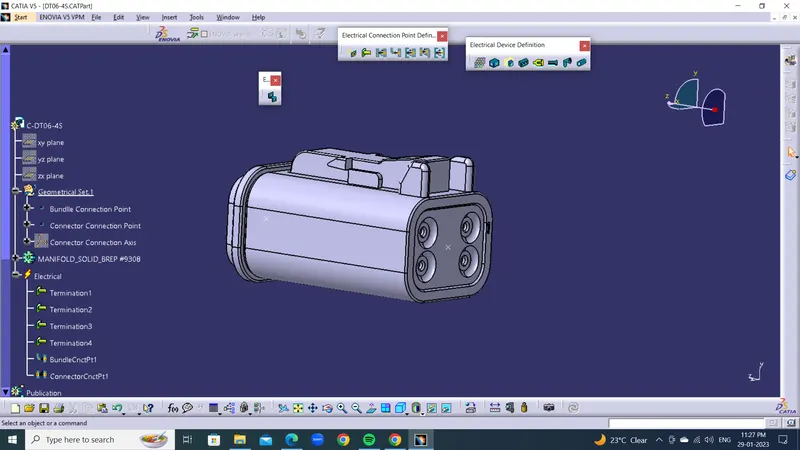
2) PART CODE : C-DT-06-4SA
QTY : 3 No's
No. Of. Terminations : 4 no's
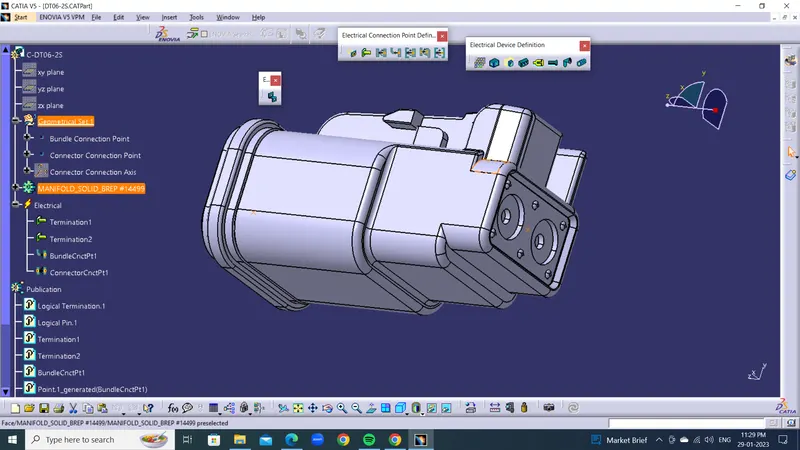
3) PART CODE : C-DT-06-2SA
QTY : 5 No's
No. Of. Terminations : 2 No's
(B) PROCEDURE FOR CLIPS & CLAMPS DEFINE A ELECTRICAL
1. Define Geometrical Properties.
2. Define Electrical support.
1. Define Geometrical Properties :
Create Points and Planes For 1st Entry and Second Entry, Add Support Planr aso fot Base support.
2. Define Electrical support .
After apply geometrial properties open Electrical part design work bench.
1. Select Electrical Support definition in Electrical part design.
2. Select 1st Entry Point and entry plane exit plane and support plane.
3.Define 2nd entry electrical support select 2nd entry point & Plane and exit is defult.
CLIPS & CLAMPS USED :
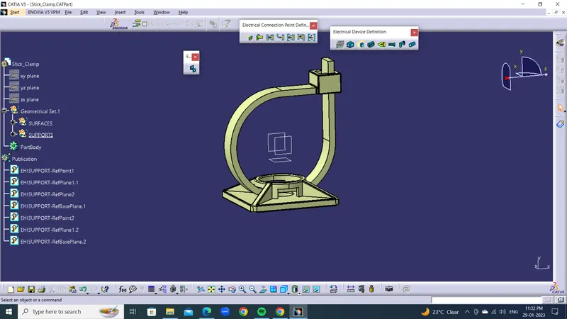
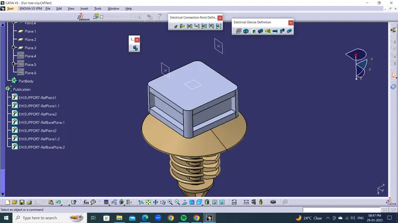
1) STICK-CLAMP
QTY : 7 No's
2) Furr tree Clip
QTY : 4 No's
3. PROCEDURE FOR GEOMETRIAL BUNDLE ASSEMBLY:
1.Add reqquired CONNECTORS , CLIPS, CLAMPS, and Mountaining Eqipments.
2. Ensure all connectors are Electrically Defined.
3. Place the Connectors given connection segments in the Engine.
4. Add the Supporting features like Clips & Clamps desired postion of Bundle routing.
5. Add Guiding Channel and place desired position in the engine For channel Define it as Define Equipment in Electrical part Design Work bench.
6.Give the Bundle connection point to the channel (on both ends and at the channel guide ways). If channel is supplied along with the wiring harness, then it has to be in the Geometrical Bundle harness Assembly.
7. Affte Devlop the positins and places of parts now enter the Electrical Harness Instalation and Define the Assembly into Bundle Segment Defination.
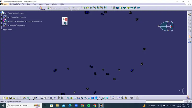
8. Now Assembly file Ready for Create Bundle Defination.
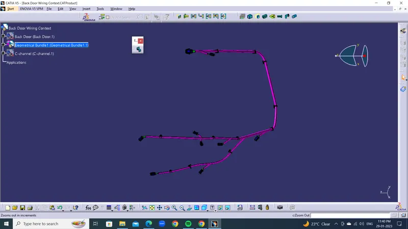
9. Create Bundle for one part to other part main Branch Dia of 12 mm. add Branch points for crating the Sub Branchs of wiring harness.
10 Create Sub Branchs with Dia of 10 mm and part Branchs Dia of 5mm.
4. Protection Covering :
Add Protectiove tubes for Safety and Bundle Holding purpose from Catalog Files.
CHECK BUNDLE CONTINUTY :
Go to Edit, Select the Search, in search go to Advance. In Advance, in workbench select the Electrical, in Type select the Bundle Segment, in Attribute select the Fully Connected option.
FLASE STATEMENT
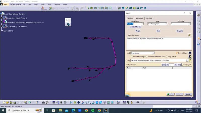
RESULT : NO open BUndle
TRUE STATEMENT
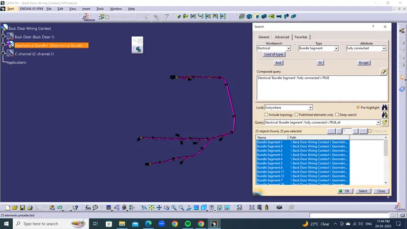
RESULT : All Bundle are Connected.
WIRING HARNESS FLATTENING
Harness Flattening tool enables users to flatten 3D geometric harness data exported from supported MCAD systems. It prepares the flattened harness structure for import into E3. formboard where the manufacturing detail can be completed. MCAD systems enable mechanical engineers to model their products in 3D.
Harness Flattening tool enables users to flatten 3D geometric harness data exported from supported MCAD systems. It prepares the flattened harness structure for import into E3. formboard where the manufacturing detail can be completed. MCAD systems enable mechanical engineers to model their products in 3D.
PROCEDURE :
1. New Product File
2. Setting Harness Flattening Parameters
3. Extract File
4. Flatten and Develop
1. New Product File :
Open catia V5 and opened a new product file and already created wiring harness assembly routing.Rename the product file into a 'Wiring Harness _Flattening'.
2. Setting up the flattening parameters:
- Switch to the Electrical Harness Flattening.
- Select the command called Harness Flattening Parameters.
- In general tab, change the minimum angle distance between them to 5 degree.
- Enable, keep existing tangent between bundle segment and connector during the flattening step.
- Also enable, Extract only the supports inside the geometrical bundle.
- Select the Radius of the bundle segment for the Roll radius for Quick roll.
- Keep the parameters default or change according to our requirement.
- Save this file as a Fattening product in the path where the required wiring harness assembly file is located.
3. Extract:
- Opened the wiring harness assembly file and tile the window vertically.
- Select the Flattening product file in model tree and select the extract command in Electrical Harness Flattening workbench and select the wiring harness assembly file to fetch the required information.
- Now the wiring harness assembly file details are extracted into the flattening product.
4. FLATTENING & DEVELOP :
- Now select the Flatten command in Eletrical Harness Flattening Workbench.
- Select the active plane as a required surface or any other required planes.
- Keep default parameters in Algorithm mode and Angle mode.
- Select the branches and select ok to perform the Flatten operation.
- Use the other commands such as rotate, roll, straighten and synchronization for the alignment of Flattening product.
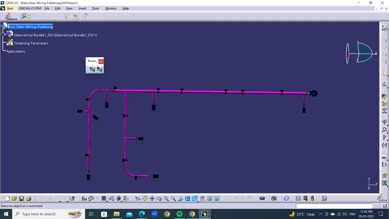
Creating 2D Harness Flattening Drawing File.
- Open the new drawing file and save as a Harness Drawing File.
- Keep ISO as a standard and A0 ISO as a sheet style.
- And select Landscape.
- Now select the Front view command in Drawing file and select the required surface or the plane for view in the flattening product file.
- Now the flatten product details are delivered into the drawing file in a 2D.
- Now go to the properties and select the view tab, under dress up section, enable the 3D colors (if needed) and also enable the 3D wireframe is always visible.
- Now the full details of flatten product details are obtained in a 2D form.
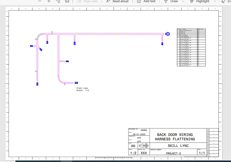
- Now the connectors are represented in a 2D. So we can change the representation into 3D by changing the flattening parameters in the flattening prodct file.
Conclusion - Routing of the wiring harness for the car Backdoor assembly has been succesfully done and prepared flatten-view drawing in Catia V5 as per the design requirements.