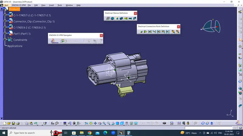
Wiring harness design in CATIA V5 - 3D modeling Week 2 Challenge
AIM :
To Download DT06-08SA , Tyco 174357-2 & Tyco 85229-1 from given link. Define Electrical part downloaded Parts.
DESCRIPTION :
CONNECTORS :
Connectors are parts or devices used for electrically connecting or disconnecting circuits etc. They can connect and disconnect by hands or with simple tools without requiring special tools or processes such as soldering.
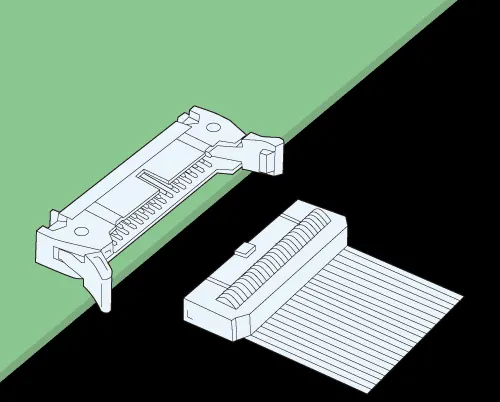
These connectors have male ends (often called pins or plugs) and female ends (often called sockets or receptacles) that mate to form a connection. Electrical connectors provide flexibility with your equipment compared to permanently hard wiring and are essential in providing reliable electrical contact and, ultimately, ease of use for your customers.
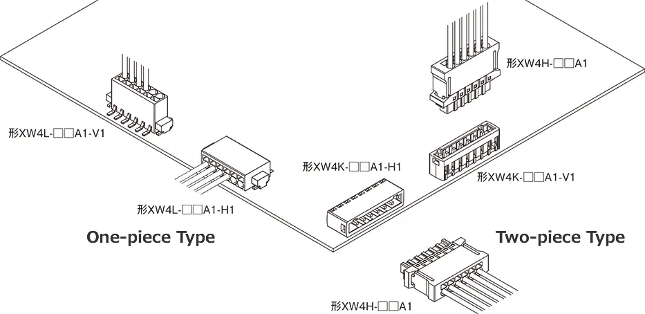
There are various types of connectors, the large majority are one-piece types that are used alone or two-piece types consisting of a plug and socket. One-piece types directly connect printed circuit boards and wires to connectors.
TYPES CONNECTORS :
Connector Basics
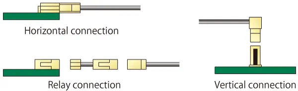
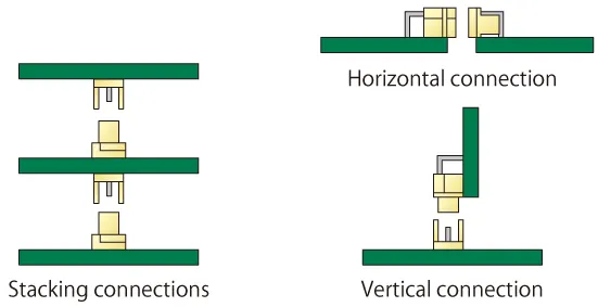
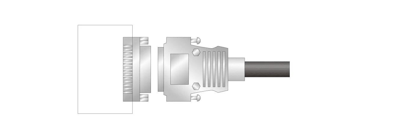
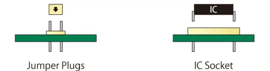
There are roughly four types of connection for connectors.
1. Board to Wire
2. Board to Board
3. Input / Output
4. Others - Jumper Plugs, IC Socket, etc.
STRUCTURE:
Basic Connector Structure
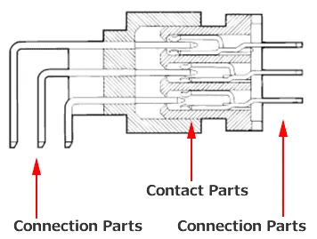
There are various kinds of connectors. Connectors have various structures and parts to be used, however, basically they consists of contacts and a housing.
Contact: Contact for making electrical connection with each other when connectors are connected
Housing: Main body part into which the contact is inatalled (Usually made of insulator)
Other parts will be added depending on the type and use of the connectors. The following is an example of D sub connector.
Shell: Outer case which houses the insulator and the contact
Eyelet: Fastener that fixes the housing and the shell
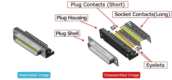
Connector image (Plug side)
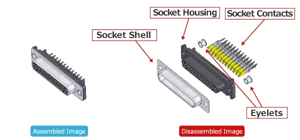
Connector image (Socket side)
PRINCIPLE :
Princle of Electrical Connectors are designed to temporarily join Conductive paths to allow electrical current to power a device or Transmit signals.
PROCEDURE FOR CONNECTOR DEFINE A ELECTRICAL PART CATIA V5 :
- Create / Download Connector 3D
- Create Geometrical Parameters.
- Define Part as Connector.
- Define Bundle Connection piont.
- Define Connector Connection point.
- Define Cavity Connection point.
Deutsch DT06 – 08SA Connector :
1. Download the Connector from given link and ope file in catia part modeling.
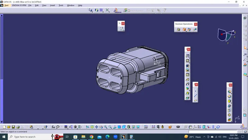
2. Create Geometrical parameters :
1. Create a point on face Bundle entry area represent name as bundle connectionpoint.
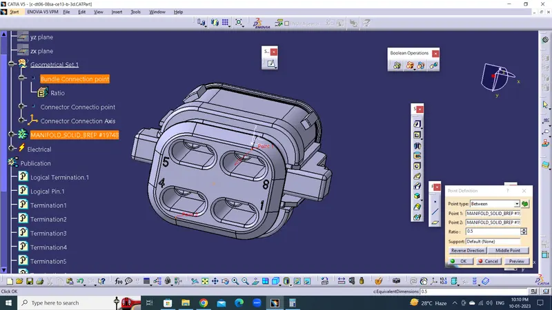
2. Create a point on face Connector meating side represent Name Connector Connection point.
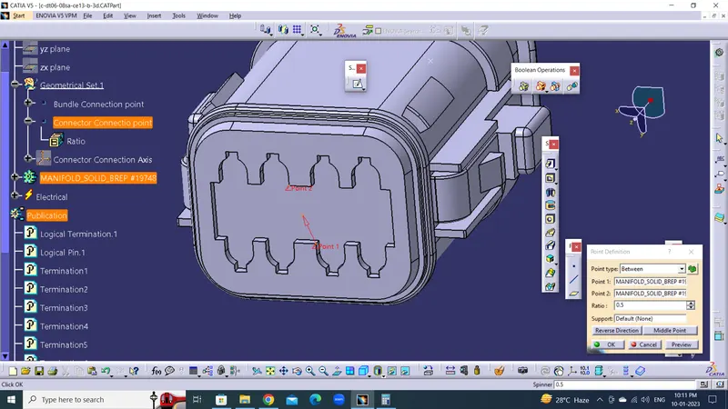
3. Create a Connector Connection axis referance of point which Connector connection point.
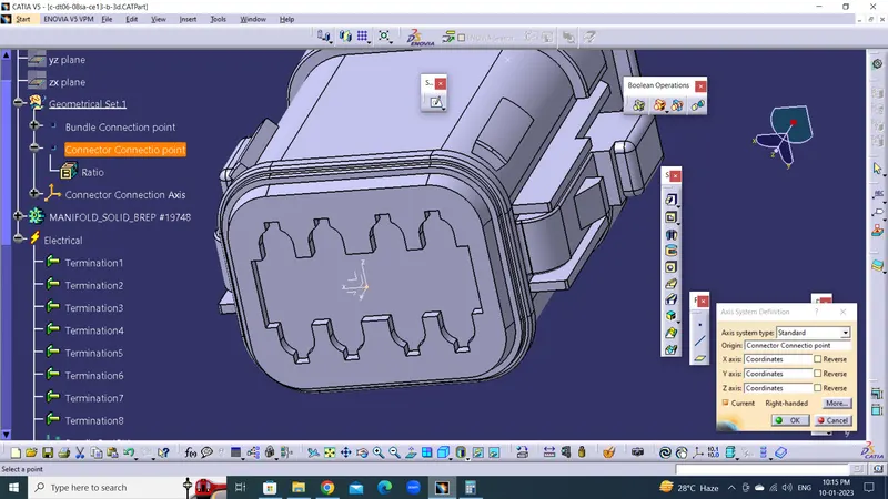
Note : In axis system The Y-Axis should be Meating direction and X-Axis Should be Locking position.
3. Define Part as Connector :
After Create geometrical parameters file change into the Electrical part design.
1. Define Part as Connector select the Define connector option in Electrical Device Defination tool bar.
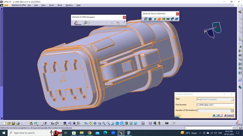
2. In Connector definitaion Type should be Single insert Connector, part name as per requirement and number of terminations are how many Bundle placed in the connecto thea number . 8 number
4. Define Bundle Connection Point:
1. Select the Bundle Connection point in the Electrical connection point definition tool bar.
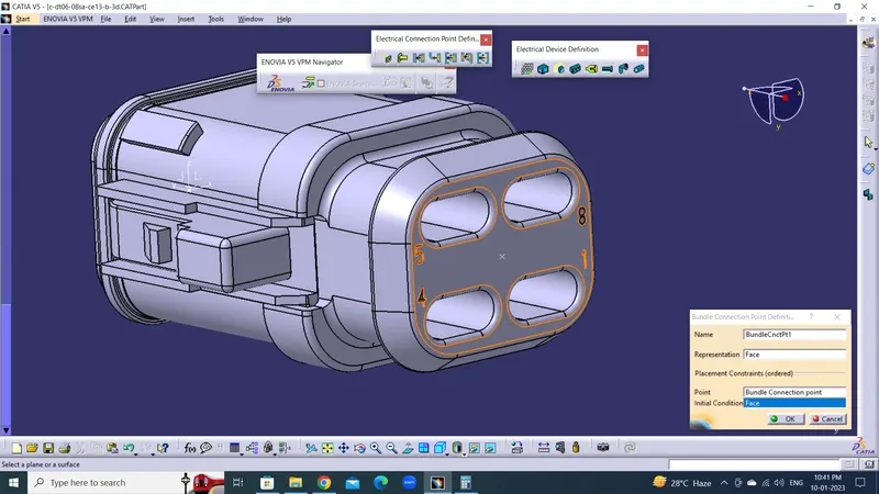
2. Representation and intial condition is the face which is Bundle entry and point is the Bundle connection point
5. Define Connector Connection point :
1. Select the define connector connection point in the Electrical connection point definition tool bar.
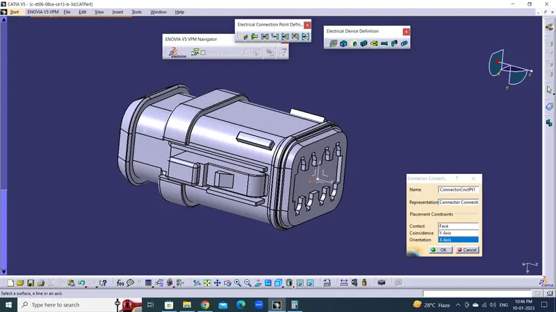
2. Representation is Connector Connectio point Contact is Face which Meating at connecton Coincidence is the Y-Axis Meatining direction and Orientation is the X-axis Locking position.
6. Define Cavity Connection point :
No Cavvity required for this connector.
Tyco 174357-2 Connector :
1. Download the Connector from given link and ope file in catia part modeling.
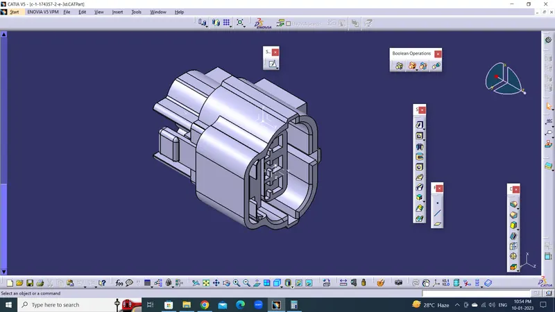
2. Create Geometrical parameters :
1. Create a point on face Bundle entry area represent name as bundle connectionpoint.
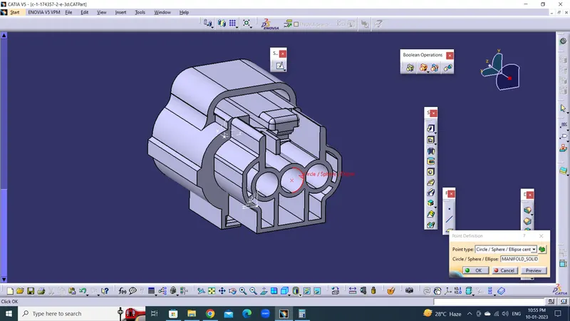
2. Create a point on face Connector meating side represent Name Connector Connection point.
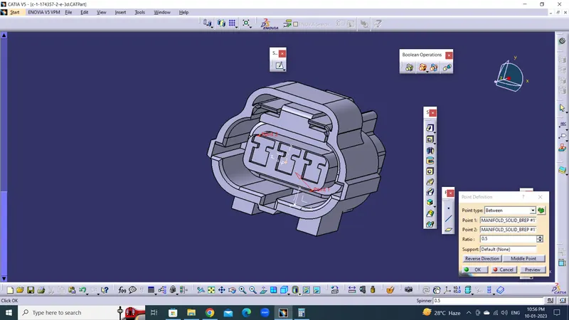
3. Create a Connector Connection axis referance of point which Connector connection point.

Note : In axis system The Y-Axis should be Meating direction and X-Axis Should be Locking position.
4. Create a point on face Connector meating side represent Name Cavity Connection point.
5. Create a Cavity Connection axis referance of point which Cavity connection point.
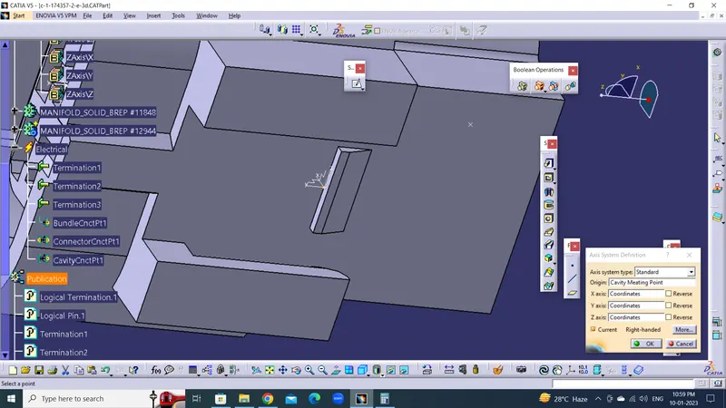
Note : In axis system The Y-Axis should be Meating direction and X-Axis Should be Locking position.
3. Define Part as Connector :
After Create geometrical parameters file change into the Electrical part design.
1. Define Part as Connector select the Define connector option in Electrical Device Defination tool bar.
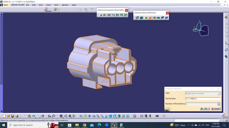
2. In Connector definitaion Type should be Single insert Connector, part name as per requirement and number of terminations are how many Bundle placed in the connecto thea number . 3 number
4. Define Bundle Connection Point:
1. Select the Bundle Connection point in the Electrical connection point definition tool bar.
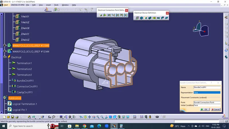
2. Representation and intial condition is the face which is Bundle entry and point is the Bundle connection point
5. Define Connector Connection point :
1. Select the define connector connection point in the Electrical connection point definition tool bar.
2. Representation is Connector Connectio point Contact is Face which Meating at connecton Coincidence is the Y-Axis Meatining direction and Orientation is the X-axis Locking position.
6. Define Cavity Connection point :
1. Select the define Cavity connection point in the Electrical connection point definition tool bar.
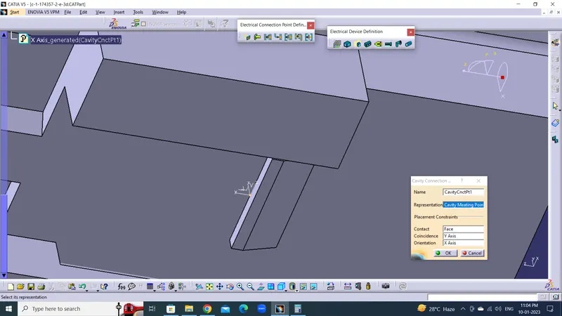
2. Representation is Connector Connectio point Contact is Face which Meating at connecton Coincidence is the Y-Axis Meatining direction and Orientation is the X-axis Locking position.
Tyco 85229-1 Cavity/ Mountaing Clip:
Description :
Mounting clips provide a secure attachment point for the receptacle side of an application when a flange mount assembly is impractical or impossible.
PROCEDURE FOR CAVITY DEFINE A ELECTRICAL PART CATIA V5 :
- Create / Download Connector 3D
- Create Geometrical Parameters.
- Define Part as Mounting Equipment.
- Define Cavity.
1. Download the Connector from given link and ope file in catia part modeling.
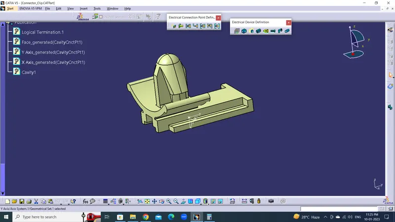
2. Create Geometrical parameters :
1. Create a point on edge cavity connection point.
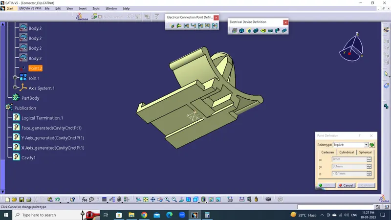 2 Create a Connector Connection axis referance of point which Connector connection point.
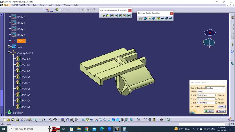
Note : In axis system The Y-Axis should be Meating direction and X-Axis Should be Locking position.
3. Define Part as Mounting Equipment :
After Create geometrical parameters file change into the Electrical part design.
1. Define Part as cavity select the Define Mounting Equipment option in Electrical Device Defination tool bar.
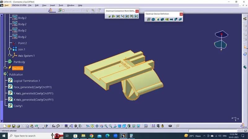
4. Define Cavity :
1. Select the Cavity in the Electrical connection point definition tool bar.
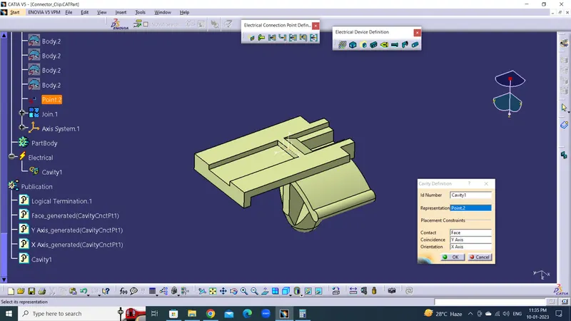
2. Representation is point Contact is face, Coincidence is the Y-Axis Meating Direction and Orientation is the X-axis Locking position.
ASSEMBLY :
After Define all electrical parameters open Electrical assembly design.
1. Select the connector Male and female shows Meating point and direction.
2. Select the connector and Cavity shoes Meating point and direction.