Hood design-Week 2
HOOD DESIGN OF A CAR
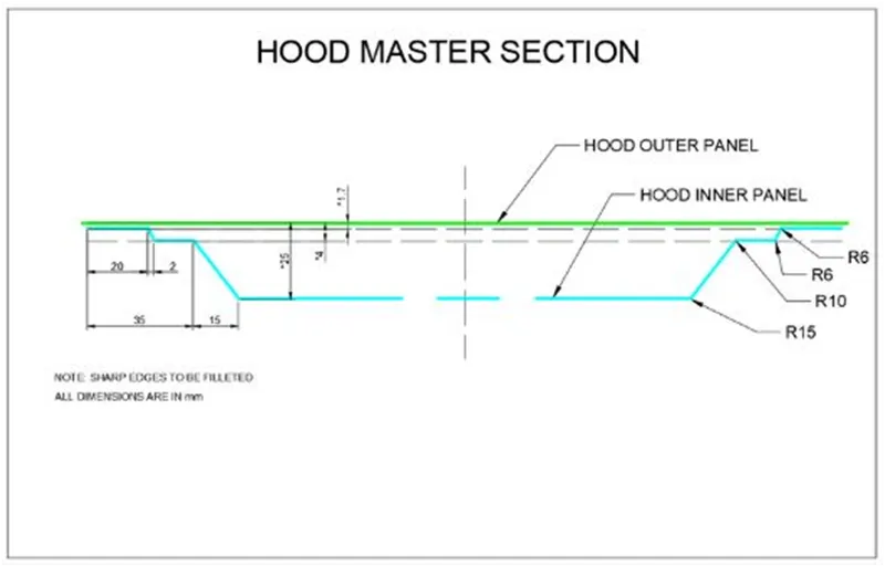
Aim: Design Hood Outer Panel, Inner Panel and the necessary reinforcements according to the given Master section.
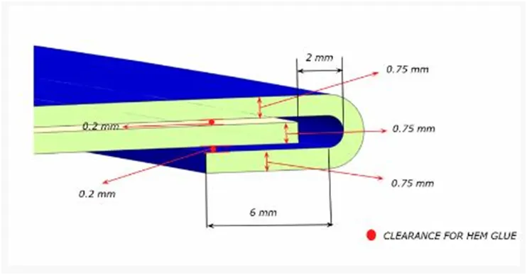
Thickness of Inner panel is 0.75mm, Outer panel 0.75mm and Reinforcement thickness 1.5mm.
Hood:
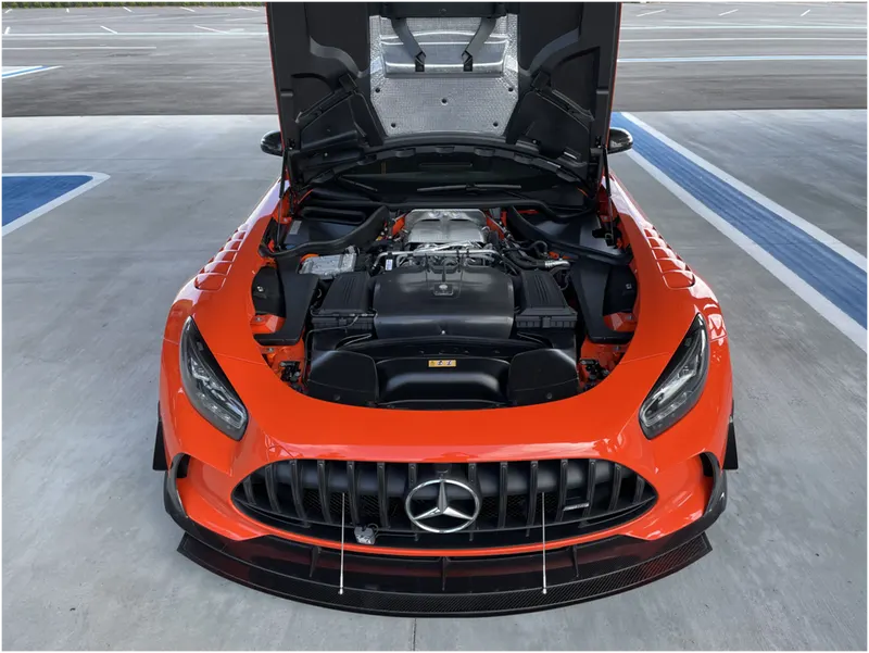
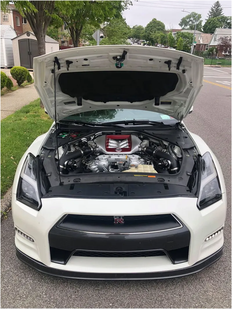
A car hood, also referred to as a “bonnet” in some countries, is the hinged cover that rests over the engine bay of a front-engine vehicle. The car hood protects the engine and connected parts from the elements while providing easy access for repairs and maintenance. Car hoods are typically constructed from steel and sometimes from aluminum. Aftermarket car hoods may be constructed from various other materials, including carbon fiber, fiberglass, or dry carbon. A concealed latch is typically used to lock the hood in place while driving. A release for the mechanism can be accessed from the dash below the steering wheel. On race cars and vehicles with an aftermarket hood, exposed pins may be used to secure the car hood. Hoods sometimes contain a hood scoop or a power bulge to allow for greater engine capacity and airflow to increase the car’s performance output.
Hood design:
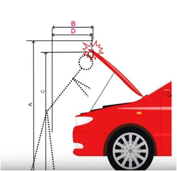
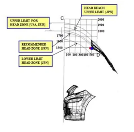
There lot more things before the hood gets in to designing hands that to be considered. The height of the hood is designed based on the country standards as the height of a average person changes from place to place. The material consideration is also required that should be cost effective to manufacture. The Hood should be designed with a light weight for the pedestrian safety as the person hi to hood there should be minimal harm to the person.
The Master section for the hood is shown below
The outer panel given is shown below
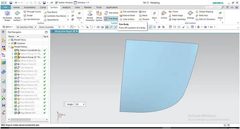
So according to the input design given the outer model should be modified to get the final input panel model. First the outer panel should be exactly halved into middle using mid plane and should work on the half angel. Then all the features should be mirrored and sewed together.
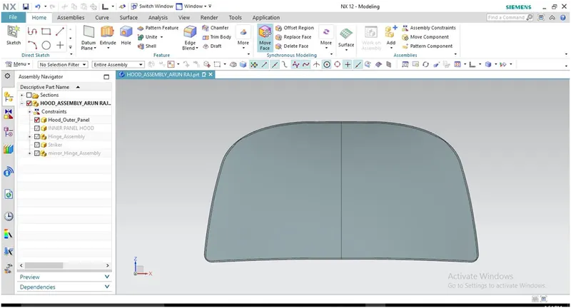
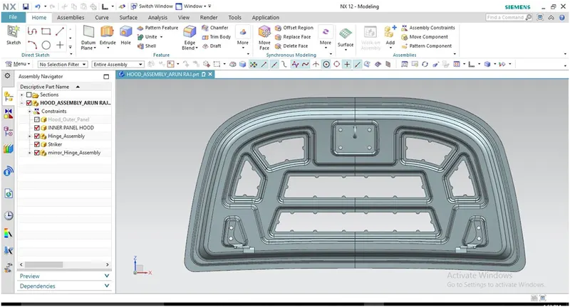
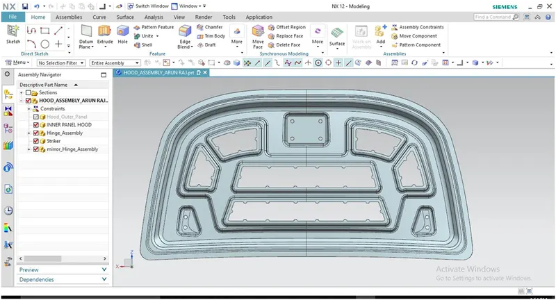
Now emboss should be created on the inner panel for removing material to get a lightweight component.
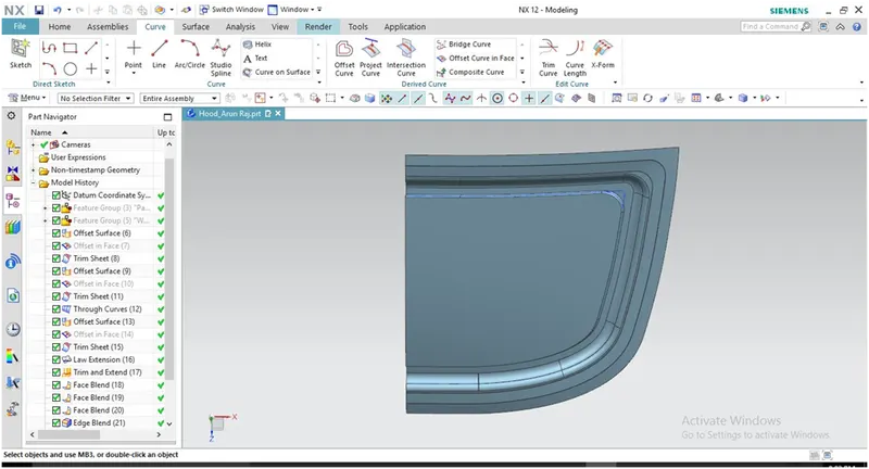
Now the features are to be built up like embosses, mastic points, embosses for hinges and latch.
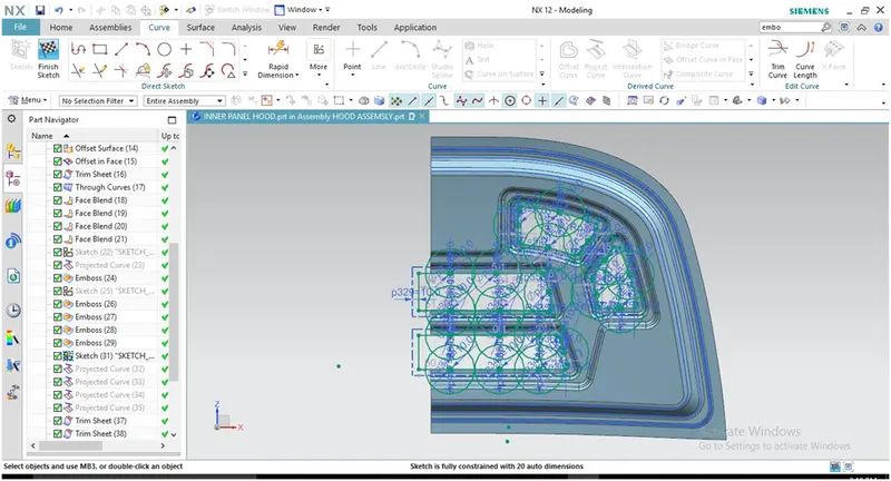
Below image is shown for mastic embosses and the hinge embosses to stick the inner panel with the outer panel mastic points were created and the maximum radial distance between them should be 80mm. So after completing the mastic points the inner panel should be mirrored and sewed together. Then the sewed feature should be examined with geometry to check any cracks were built in between.
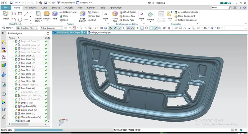
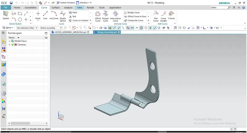
Now the Hinges should be attached at the ends of the embossed inner panel edges.
Hinge placement:
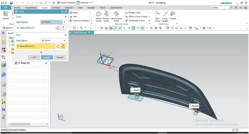
First hinges are placed on the embosses and as inner panel is applied with fixed constraint hinge is placed parallel and touch constraint. Then the hinge is mirrored with associative connection to other side to get the same hinge position on other side of the inner panel.
Latch attachment::
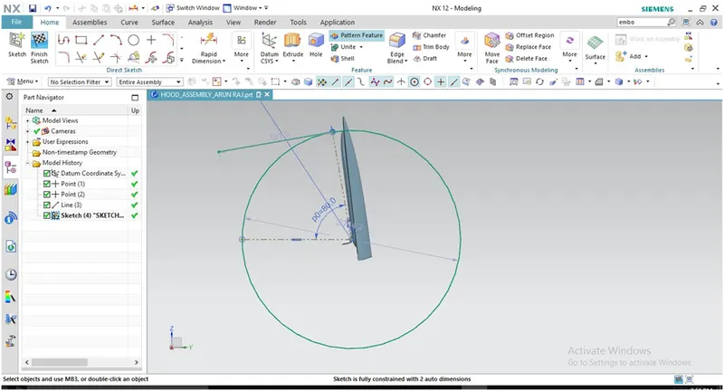
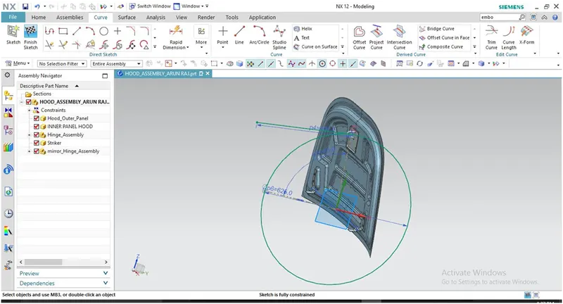
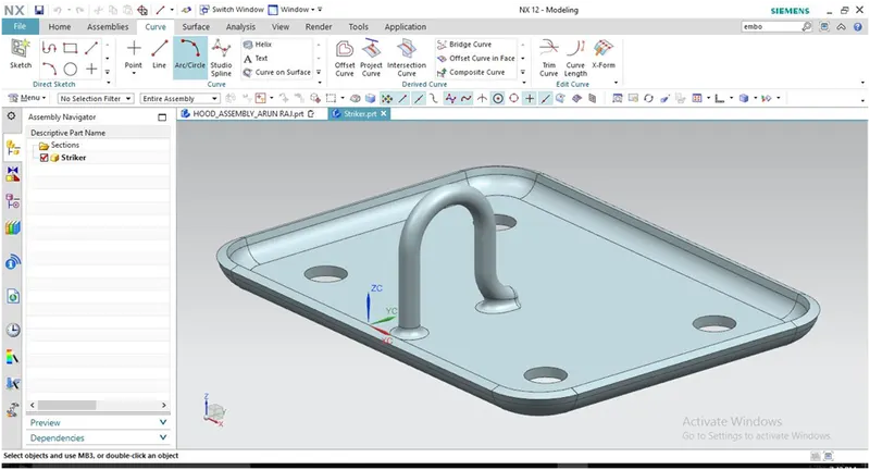
The latch/Striker is position from the basis of hinges centre point. Two points is marked from the two hinge axis and a line is drawn from the two points. A midpoint is taken from the line for positioning the latch. Now a circle is drawn as that point as a centre with a radius of approximately around 300mm(based on the hood designer) and the tangent line is drawn on that circle. Then latch iscoincided with that tangent line. So after latch position is fixed then the emboss is created from the latch surface using wave geometry linker in to the inner panel file. Striker emboss is shown in the below image.
Hemming operation :
Hemming is a forming operation in which the edges of the sheet are folded or folded over another part in order to achieve a tight fit. Normally hemming operations are used to connect parts together, to improve the appearance of a part and to reinforce part edges. In car part production, hemming is used in assembly as a secondary operation after deep drawing, trimming and flanging operations to join two sheet metal parts (outer and inner) together. Typical parts for this type of assembly are hoods, doors, trunk lids and fenders. The accuracy of the hemming operation is very important since it affects the appearance of the surface and surface quality. Material deformations, which occur during the hemming process, can lead to dimensional variations and other defects in parts. Typical hemming defects are splits or wrinkles in the flange, material overlaps in the corner areas or material roll-in. This is why it is important to use simulation tools in order to, on the one hand, better understand the hemming process and, on the other hand, significantly reduce the number of “trial and error” loops during tryout und production.
There are various types of hemming operations:
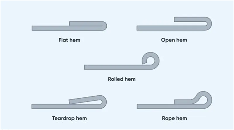
- Flat or closed hem: In a flat or closed hem, the part of the edge that bends sits completely flush over the rest of the metal sheet. The angle between the returning flange and the sheet metal is 180 degrees. The inside radius is zero and thus, there is no gap between the returning flange and the metal sheet. Closed hems require a lot more power and tonnage from the presses than open or teardrop hems and it is also not advised for metal sheets that are over 2-3mm in thickness since the sheets are likely to fracture.
- Open hem: In an open hem, the returning flange is folded over the sheet metal but there remains an air pocket between the two. The bend angle in this hem type is also 180 degrees.
- Teardrop hem: In a teardrop hem, the returning flange is bent beyond 180 degrees. The resulting shape resembles a teardrop. It is perfect for materials that do not have the required ductility to provide closed hems. Teardrop hems are used for fragile materials such as aluminium.
- Rope hem: A rope hem has a returning flange at a bent of more than 180 degrees. Once the hem achieves the shape of an open hem, the returning flange is pressed onto the part surface through a flattening die. The edge is bent in shape similar to an open hem and then the second piece to be connected is inserted into the gap between the metal sheet and the returning flange. Further pressing takes place making the second parts sit flush between the metal sheet and the returning flange and create a joint.
- Rolled hem: In a rolled hem, the bent portion of the sheet metal is tucked back into itself. This creates smooth round edges all around for holding the part from the hemmed edges. This process is also commonly referred to as curling.
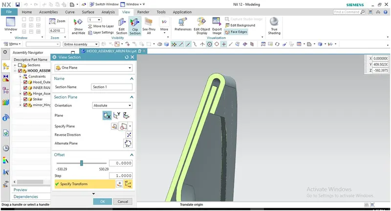
In this project the outer panel is first offset to the distance below inner panel with all thickness and allowances are provided and using law extension command and face blend command hemming process is done.
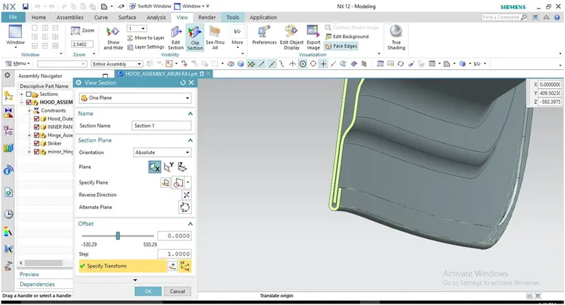
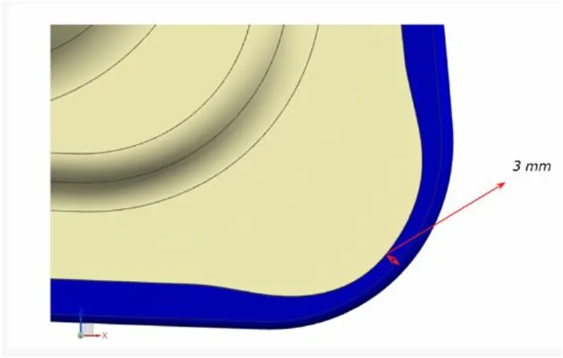
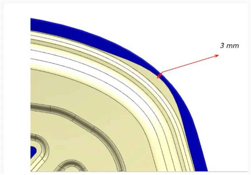
Corner Relief: Corner relief is provided on the outer panel to release the stress concentration at the corner.
Reinforcement part creation:
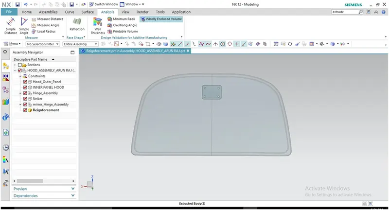
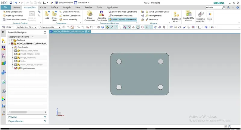
We can create reinforcement part in assembly work bench By using WAVE Geometry linker and thicken option. Thickness of the Part is 1.5mm.
Conclusion: The Automotive hood design is successfully done by referring the given master section and parameters.
Individual Parts:
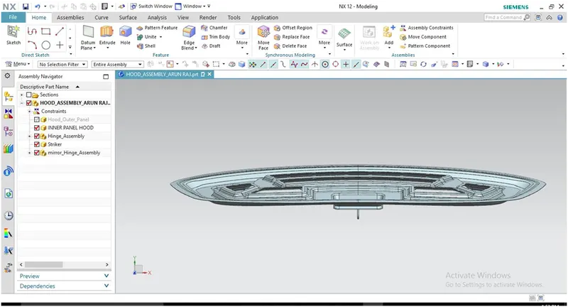
- Inner Panel:
- Outer Panel:
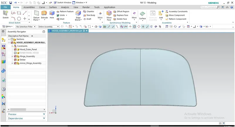
- Latch & Striker:
- Hinge
- Reinforcement:
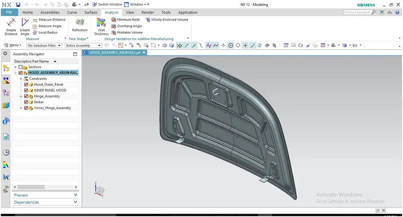
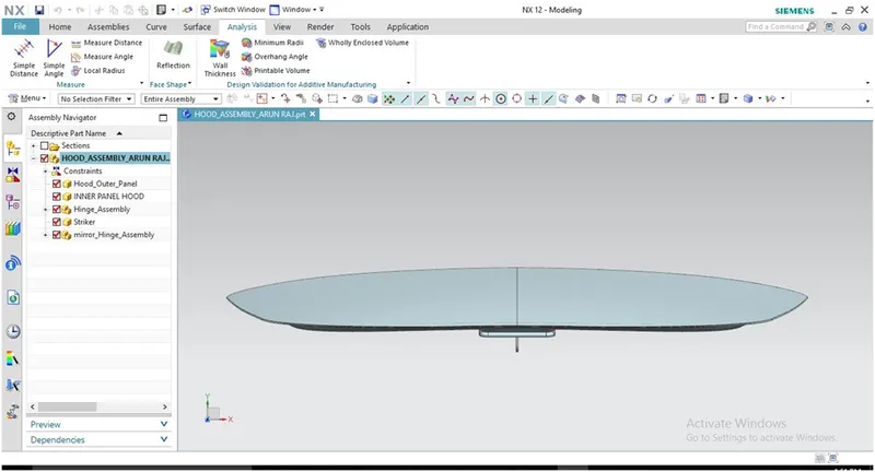
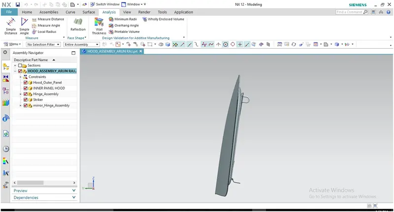
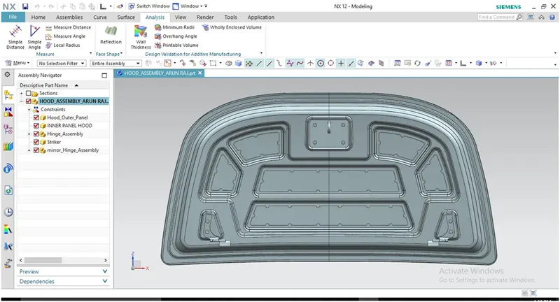
Screenshots of Final assembly: