Wiring harness design in CATIA V5 - 3D modeling Week 5 & 6 Challenge
WIRING HARNESS DESIGN IN CATIA V5 - 3D MODELING WEEK 5 & 6 CHALLENGE
Q1. Route the following harness layout in Electrical workbench. Make assumption for harness bundle diameters. Use the connectors provided. After completion of routing,
- Check the bundle Continuity. Add snap of result in submission
- Add annotation to all connectors. Make an assumptions for annotations like connect 1, 2 etc
- Check for the bundle warning. Add snap.
- Generate .CATpart of harness assembly and convert is in .igs format.
Routing data:
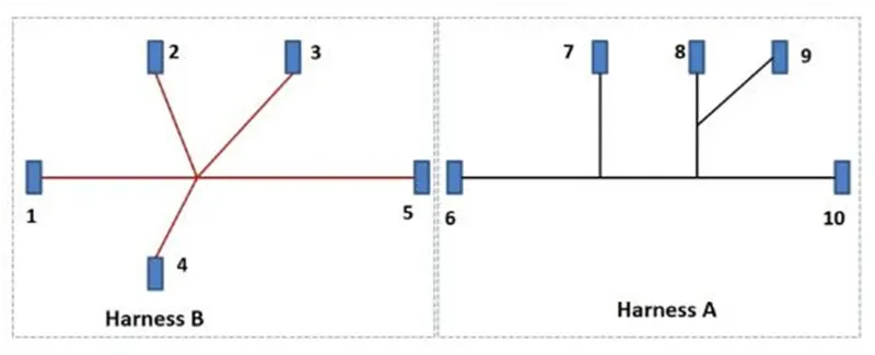
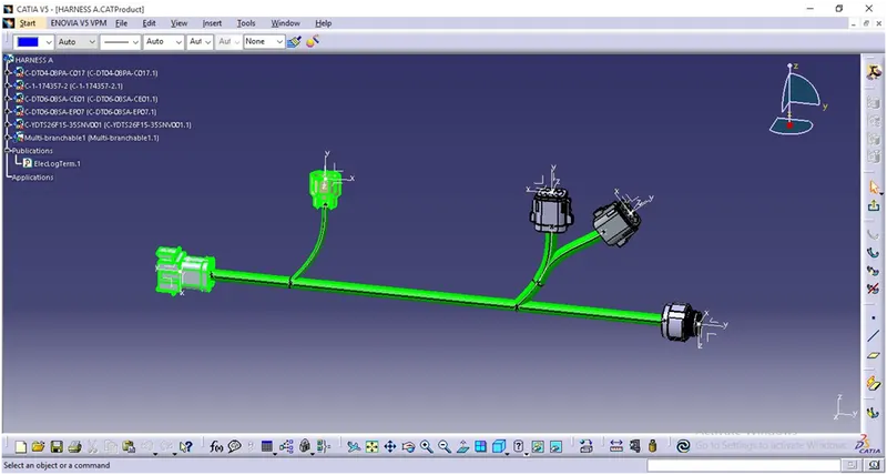
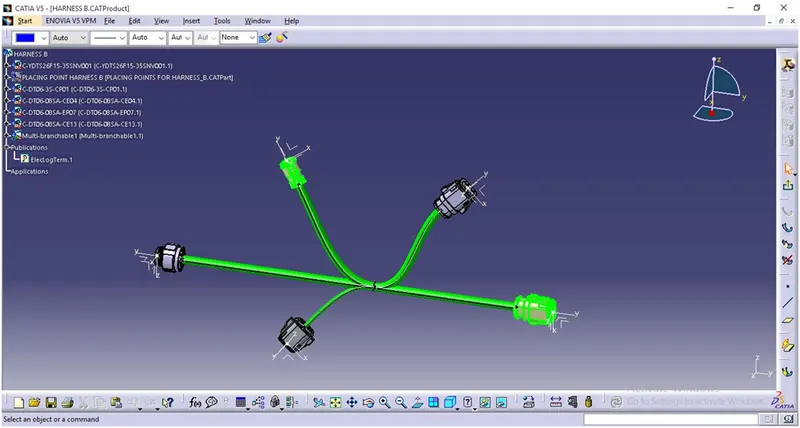
Ans: Above figure shows the layout of two Harness A and Harness B
The electrical connectors are represented by numbers in the above figure.
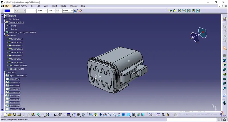
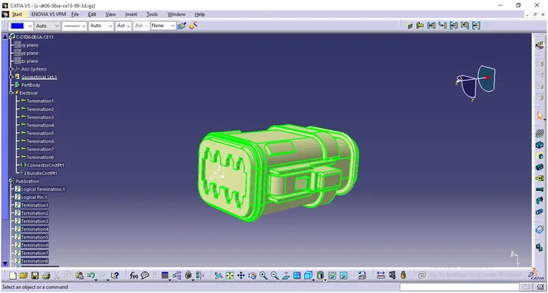
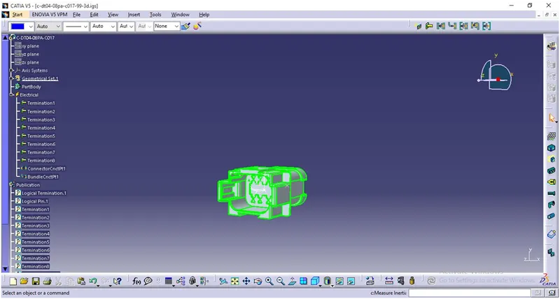
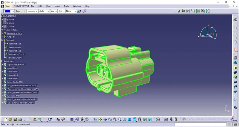
There are 8 different types of connectors at 10 different locations. All these connectors are electrically defined and added to the catalogue.
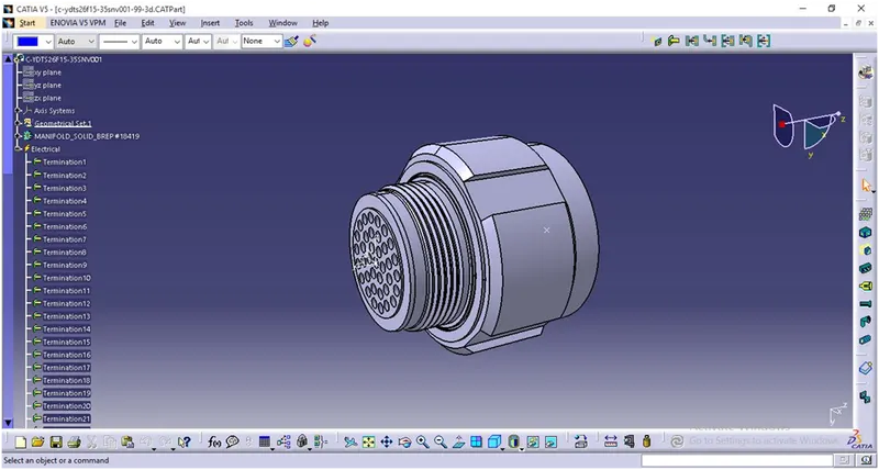
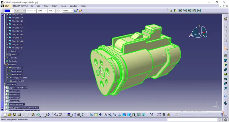
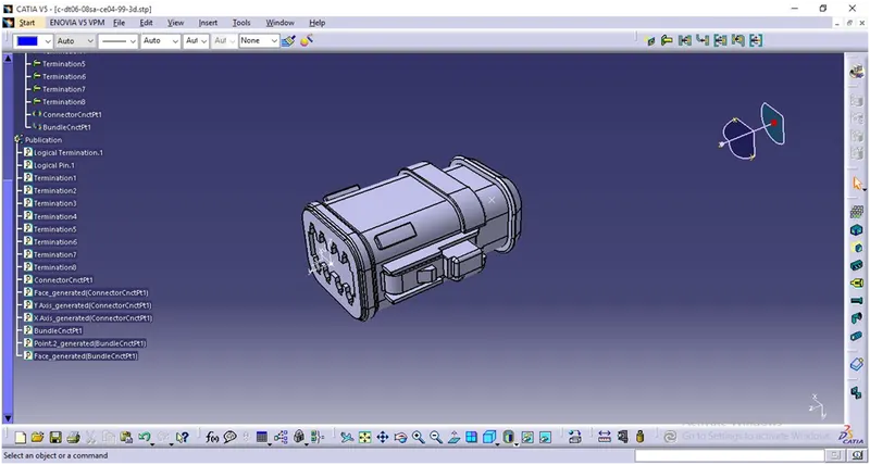
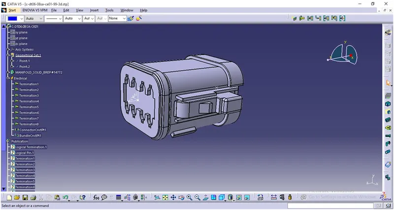
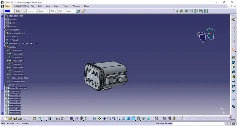
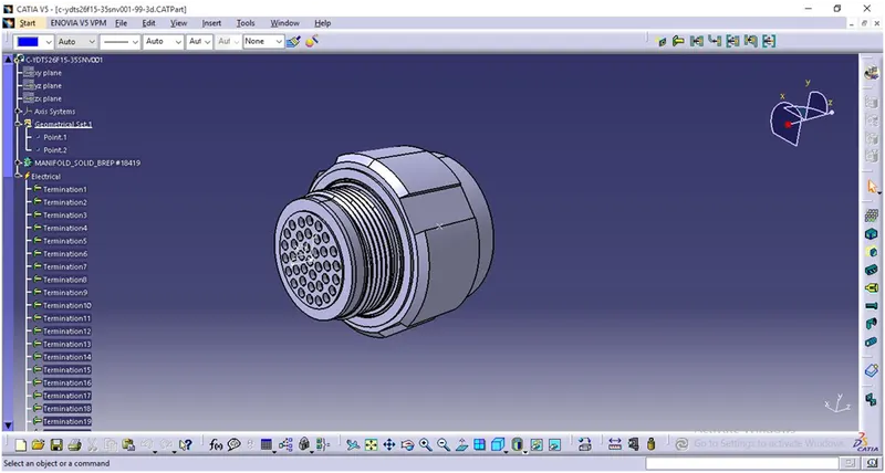
- Bundle continuity has to be checked for the two created harnesses.
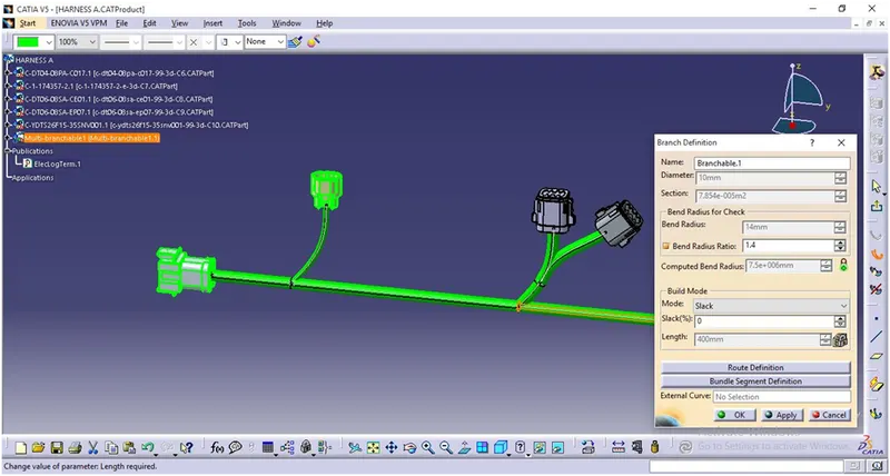
- After the two Harnesses are created, the next objective is to have them interconnected electrically.
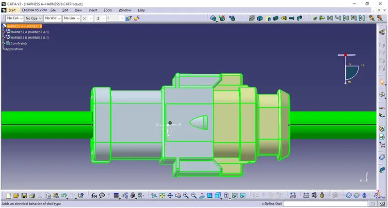
- Check connectivity for bundle warnings in Harness A and Harness B.
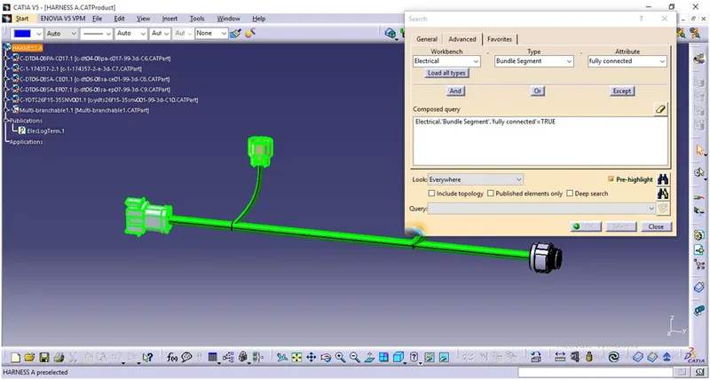
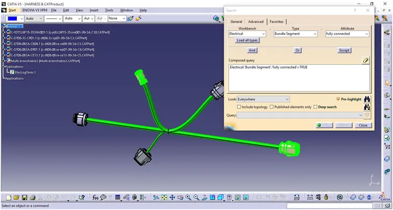
- Add annotations to all the connectors in Harness A and Harness B.
HARNESS A:
HARNESS B:
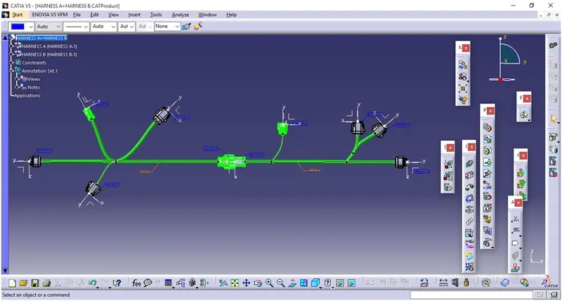
HARNESS A & HARNESS B CONNECTION:
Above image shows Harness A & Harness B assembly.
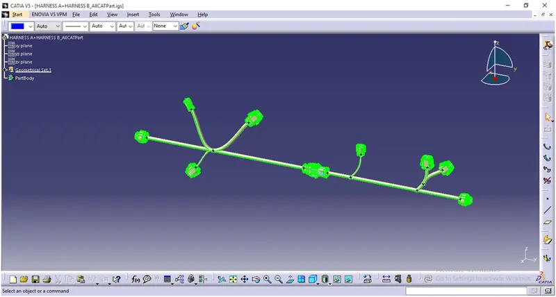
Finally the .CATProduct file is saved as .CATPart and .igs files.
CONCLUSION: Routing of electrical harness is done using given data and parameters also the file saved in .igs format.