Fender Design
FENDER DESIGN
Aim:
To design the fender by using the given master section for drip area and to design the sill, Bumper, Baffle and A-Pillar mount according to the engineering standards.
Objective:
- Study about fender and its type and the parameters need to follow.
- Design the drip area according to the given master section and also sill, Bumper, Baffle and A-Pillar mount.
Explanation:

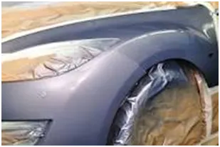
Fender is the part of an automobile, motor cycle or other vehicle body that frames a wheel well (the fender underside). Its primary purpose is to prevent sand, mud, rocks, liquids and other road spray from being thrown into the air by the rotating tire. Fenders are typically rigid and can be damaged by contact with the road surface.
Sticky materials such as mud may adhere to the smooth outer tire surface, while smooth loose objects such as stones can become temporarily embedded in the tread grooves as the tire rolls over the ground. These materials can be ejected from the surface of the tire at high velocity as the tire imparts kinetic energy to the attached objects. For a vehicle moving forward, the top of the tire is rotating upward and forward, and can throw objects into the air at other vehicles or pedestrians in front of the vehicle.
Types of Fender:
There are mainly two types of fenders,
- Full bumper type:
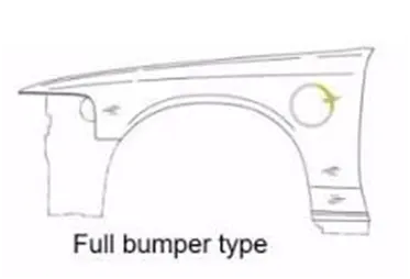
The full bumper type model is used in the older days this creates much wastage of material and the unnecessary cost is increased.
- Half bumper type:
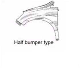
This half bumper type is used for mainly cost and material cutting purpose as this type is also provides ease of manufacturing and the strength is also improved for half bumper type fender.
Design parameters:
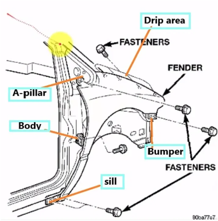
The front fender is manufactured as a separate part, this is then mounted to the body of car for this the front fender basically has 5 mounting points can differ from one OEM to another OEM. The following is the important areas.
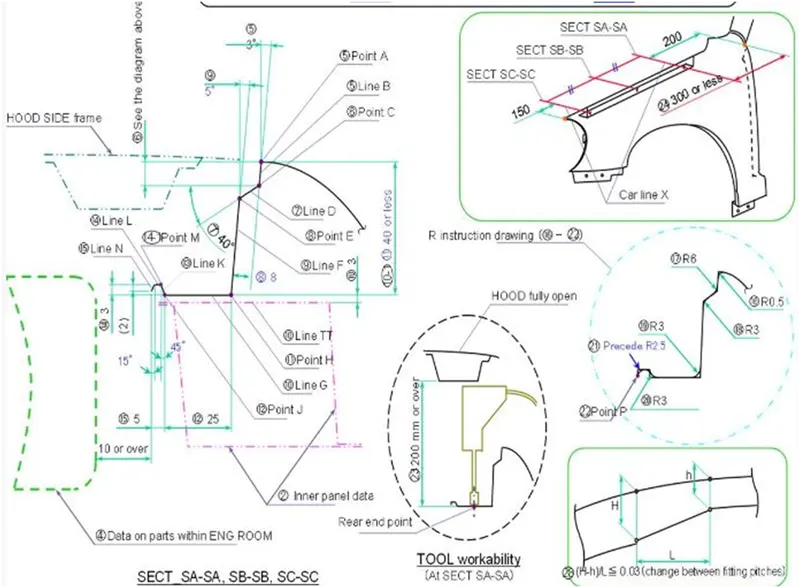
Drip area mounting is the important part in the fender. This mounting is attached to the engine compartment of the car. Fender drip area is mounted via weld nuts to the engine compartment. A minimum of 150mm distance is kept from the front side and a distance 300mm or less can be kept on the rear side. The total length of drip area from the top of fender should be less than 40mm. This is to avoid the spring back during the manufacturing. The edge of the mounting should at least 10mm away from any nearby component in the engine. A rigidity bead is provided at the end to increase the strength of the mounting.
- A-Pillar area: The A-pillar area mounting depends upon the A-pillar of the car. The mounting can also be provided with ribs to strengthen the part. This mounting is critical in design as it has to be mounted on A-pillar properly.
- Body side area: Another mounting point is created for the body side on the fender. This mounting is created such that it can be mounted on the body of the car. It may consist of one or two bolting holes.
- Sill area: Sill area mounting is also an important mounting part. This mounting point is basically on the bottom of the fender. The mounting should be created such that the fender is firmly attached to the sill.
- Cowl area:Sometimes fender is also provided with the cowl area mounting. This mounting is on the top side of the fender. It is used to attach the extruded rubber sheet material over the wheels.
Design Procedure:
The skin data from given file is we need to open first in the NX cad software and in that we need to create the some mounting area for the fender. So for the fender mounting is has the different types usually it’s vary for OEM to another OEM. So here we are going to create the Drip area, A-Pillar, sill area, Bumper mountings and Baffle mountings area on the given part.
The Design parameter for Drip area mount is given below.
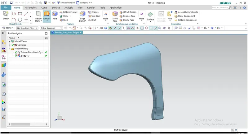
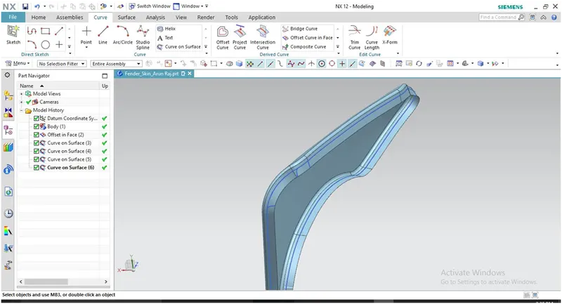
From the skin data first we need to offset the edge curve for 5mm for trim the remaining surface to reduce the material and for the required mounting places leave the area next step is draw the curve on the surface by using curve on surface tool as shown in figure.
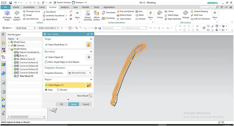
Then the next step is to trim the unwanted surface by using the trim sheet tool as shown in figure. And also need some surface area for another mountings as well.
Create the surface over there using the law extension tool we create the surface as shown in figure.
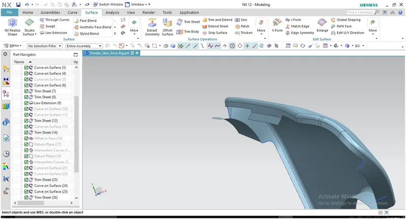
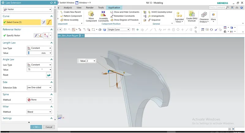
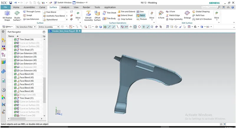
After creating this surface next step is to create the face blend for smooth the surface area as shown in figure for all the extended surfaces.
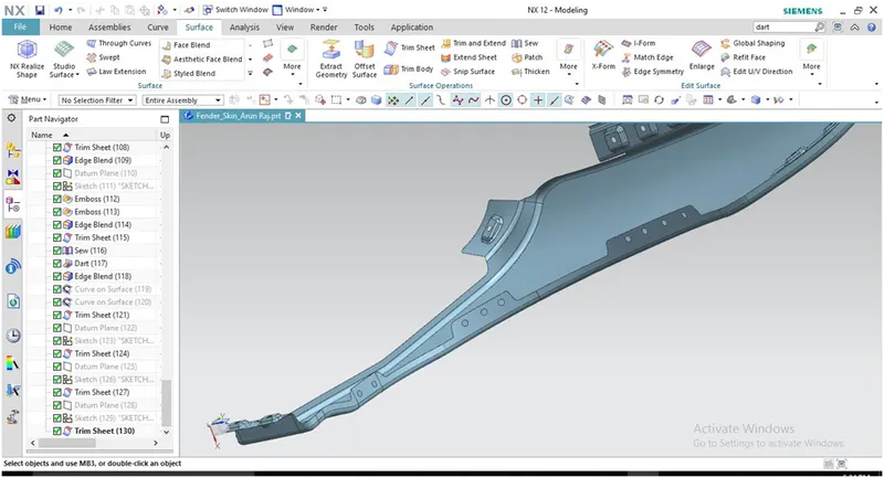
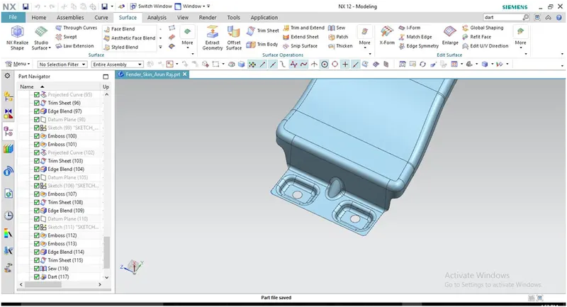
Then next step is to create the mounting hole in the cowl area.
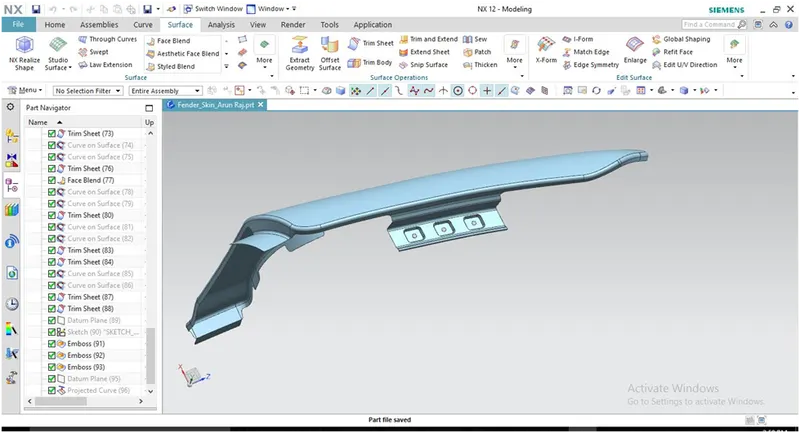
After the sketch is done next step is to create emboss the sketch for emboss for the 3.5mm as shown in figure.
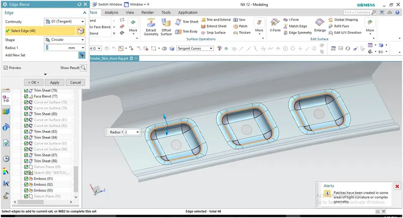
After create this required emboss then need to smooth the surface by using the edge blend tool as shown in figure.
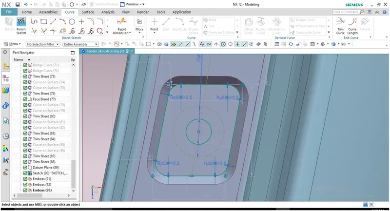
After doing emboss the surface next step is to create the sketch on emboss to create the hole. And create the hole for 5mm radius and leave some space for 10mm as shown in figure.
Use trim sheet option to cut the hole.
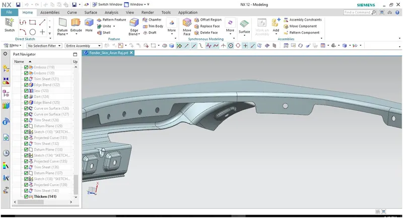
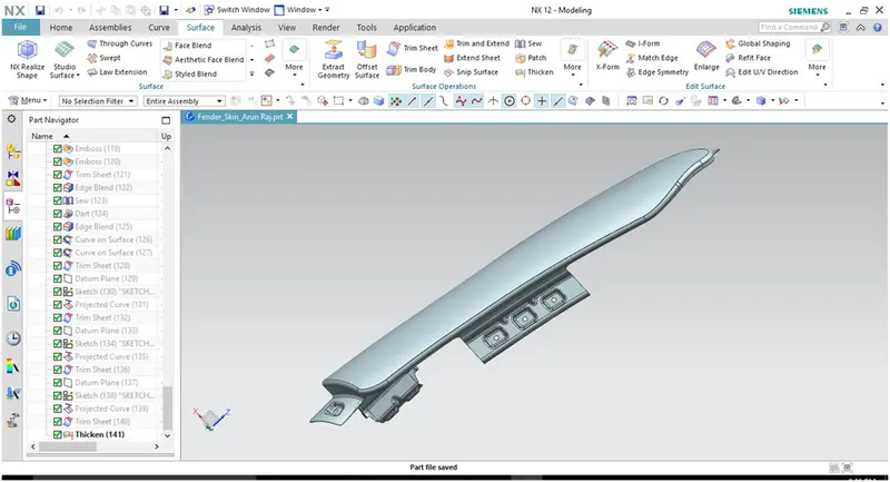
So this is the Drip area has completely done. And by this way we need to create the other required mounding as well as shown in below figure.
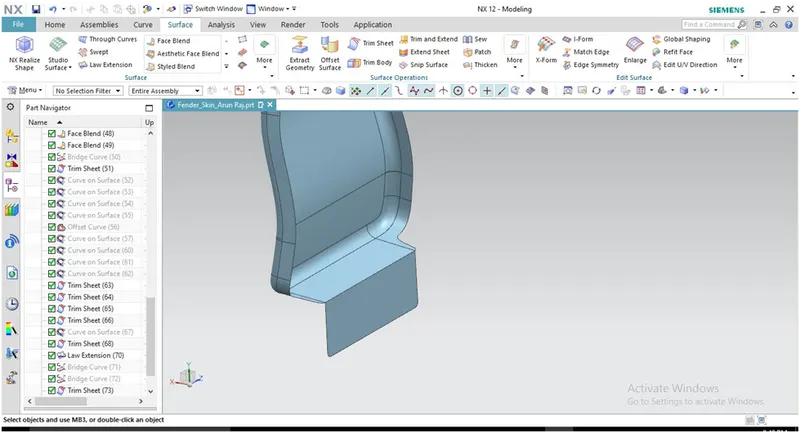
After work on all the areas the part should be thickened to 0.75mm inward direction.
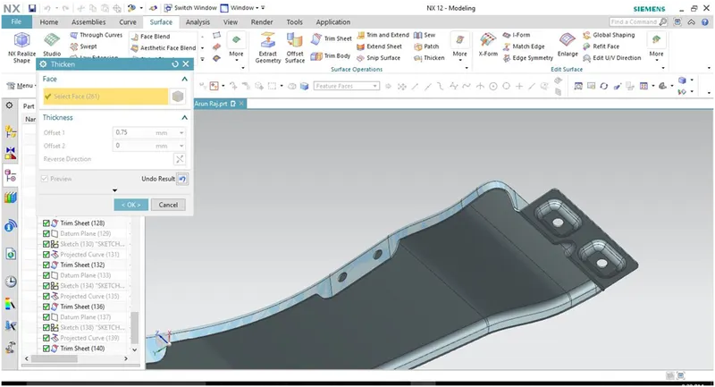
Screen shots of individual portions:
A-Pillar area:
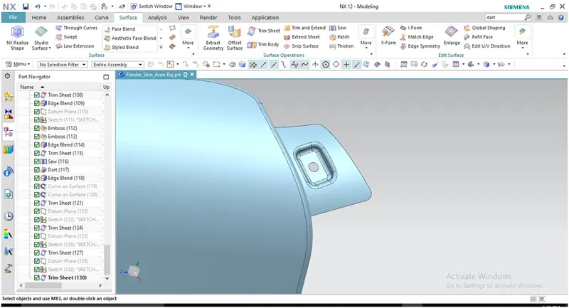
Bumper mounting:
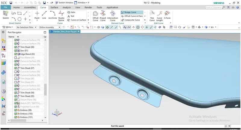
Drip area:
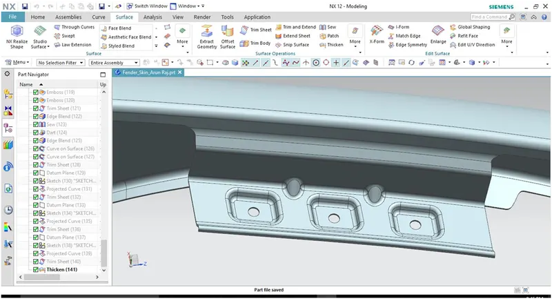
Sil area:
Cowl Area:
Screenshots of different views:
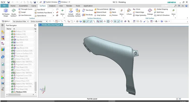
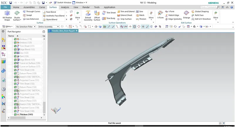
Conclusion: Design of the fender by using the given master section according to the engineering standards is done successfully.