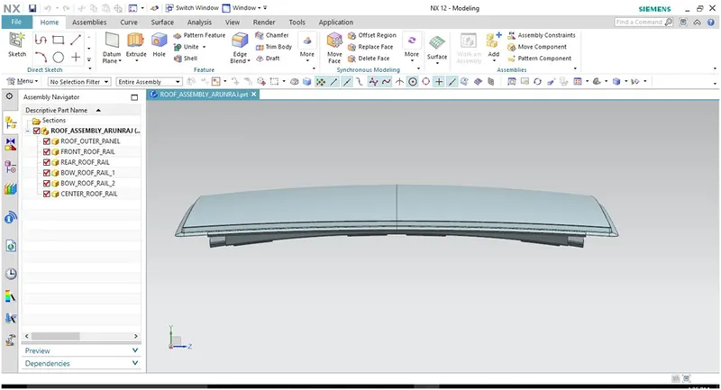
Roof Design
DESIGN OF ROOF
OBJECTIVE:
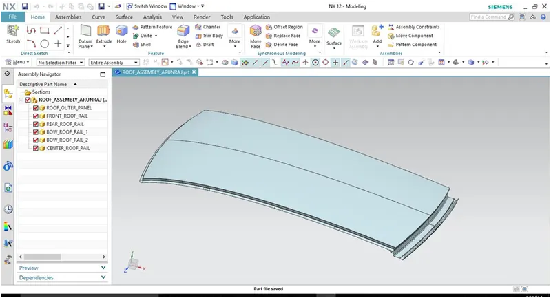
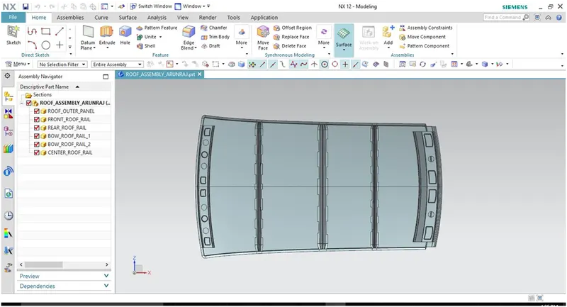
- Main objective of the project is to create the Roof Sheet metal design in NX cad, and also designing Front roof rail, rear roof rail, bow roof front, bow roof rear, center roof rail and Reinforcement are creating to build the strong roof.
- Do curvature study on Roof and performance calculations for Heat distortion and snow load criteria to determine the position of the Bow roofs.
- Finding the moment of inertia and section modulus for Bow-roofs and center roof rail.
- Also finding the Draft Analysis of each part.
SOFTWARE USED:
NX 12.0
- To design the Sheet metal ROOF in NX by using some Solid/Surface features.
- NX Software is a flexible and powerful integrated solution that helps you deliver the products faster and efficiently.
- NX Cad software is widely used automotive, aerospace, thermal power station. Because of its having modeling, drafting and manufacturing platform.
INTRODUCTION:
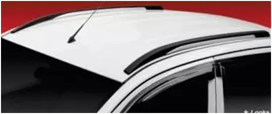
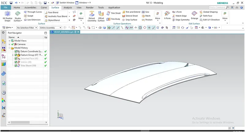
An automobile roof or car top is the portion of an automobile that sits above the passenger compartment, protecting the vehicle occupants from sun, wind, rain, and other external elements. When it is seeing from outside of the car, it is just closing the top portion. But in design point of view, it is hard to create the design. Because of you have to create no of support rails for enough strength to withstand the load. Bow roofs are primarily fixed in flatter region to enhance strength.
Front roof and rear roof rails are fixed to the ditch area using spot weld operation. But front, rear bow roof and center roof rails are fixed to roof using mastic sealants. We don’t want so many gaps between roof rails and bow roof area. So, we reduce the NVH issues.
DESIGN CONSIDERATION OF ROOF:
- Visibility criteria
- Head room clearance
- Bow roof position
- Curvature study
- Heat distortion and Snow load criteria
- Draft analysis
WHY REINFORCEMENTS:
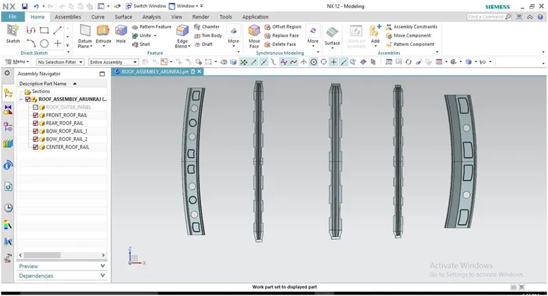
If the roof is flat it is very weak and cannot able to with stand the forces like snow , so in order to increase the strength of the roof these reinforcements like front roof rail, central roof rail, rear roof rail and the bow roofs are introduced and joined to the flat surface of the roof with the different joining process.
Different types of reinforcements that the car has are:
- Front roof rail
- Bow roofs
- Central roof rail and
- Rear roof rail
- FRONT ROOF RAIL:
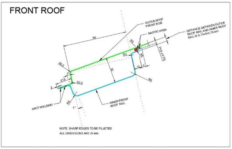
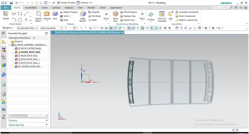
Front roof rail is the one which joins the wind shield glass, body side outer and the inner panel also. Here the front roof rail is designed based up on the master section given.
2. REAR ROOF RAIL:
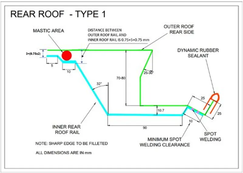
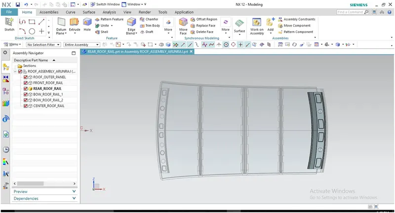
Rear roof rail is the one which joins the back door and the body side outer.
3. CENTRAL ROOF RAIL:
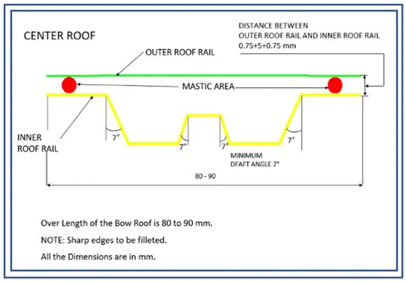
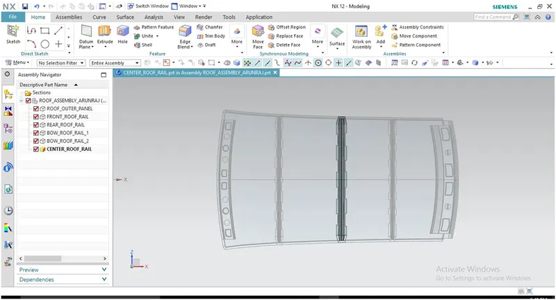
Central roof rail helps in providing effectively support to the flat area of the roof as it is more susceptible to failure under the action of load . generally central roof rail is placed at the center of the roof which is connected to the B-pillar support structure . This central roof rail helps in adding the strength to the roof during the rool-over test.
4. BOW ROOFS:
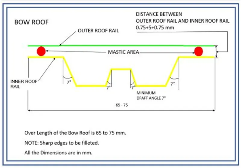
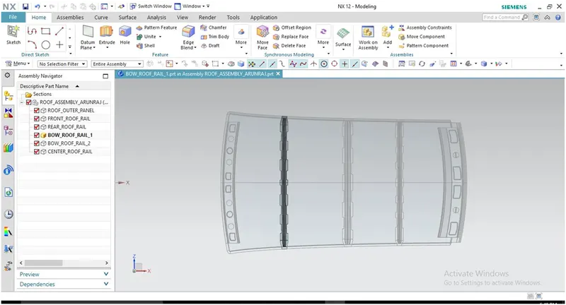
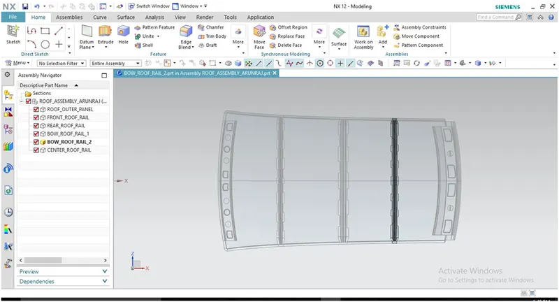
The bow roofs are given to improve the torsional stiffness and load bearing capacity of the roof structure. The number of bow roof present is depends on the overall size of the roof. Presently in this project two bow roofs are added.
JOINING PROCESS:
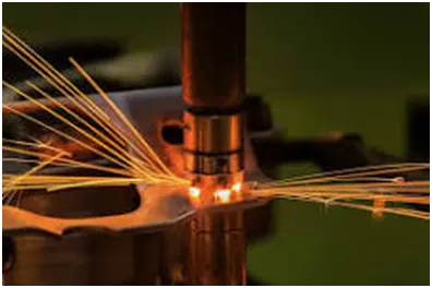
Spot welding (or resistance spot welding) is a type of electric resistance welding used to weld various sheet metal products, through a process in which contacting metal surface points are joined by the heat obtained from resistance to electric current.
Spot welding is also introduced to join the reinforcements and the outer panel.
ROOF CRUSH TEST:
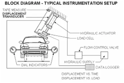
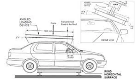
Roof crush test is the design given by the IIHS (insurance institute of highway safety). After analyzing the many accidents IIHS has then fixed some regulations, that how to perform the crush test .
IIHS gives the rating based up on this test . For this they consider two points while giving the rating.
- How fast the car can reforms to its original shape after the roll over.
- How deep is the protrusion after the roll-over.
GOAL OF ROOF CRUSH TEST:
To minimize the protrusion into the occupant compartment, so that the seat belts and air bags can do their job in protecting the occupant.
CONDITIONS TO FOLLOW FOR ROOF CRUSH TEST:
There are two conditions that should be followed for the roof crush test, they are
- Close and lock all the doors
- Close all the windows
METHOD OF APPLYING THE FORCE:
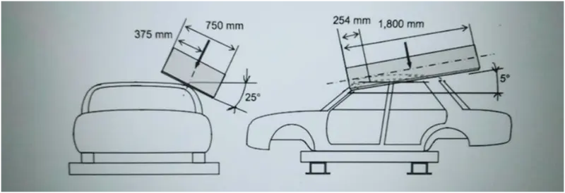
The load is applied in such a way that the hydraulic loader is tilted from the front end to the rear end and the load will be in 1800 mm in length and 750 mm in width . The load is applied at the position of 25° from the flatness of the roof. The load is applied on the roof for almost 120 sec and the crush speed at which the load applied is 13 mm/sec or less than that.
RESULTS:
If the displacements go above the requirements level then we have to increase the bow roof thickness or add more mastics points to increase the strength. The stronger the roof the better it can protect the occupants in the rollover crashes.
HEAT DISTORTION STUDY ON THE ROOF:
The heat distortion study plays a major role in sheet metal usage. Heat distortion temperature is a temperature limit above which the material cannot be used for the structural applications. This study is used to predict the heat distortion temperature at where the material starts to soften when exposed to a fixed load at elevated temperature. In order to avoid bending or damages on the roof, based on the heat distortion temperature, this study will predict the bow roof position which helps to strengthen the roof.
a. BOW-ROOF PREDICTION FORMULA:
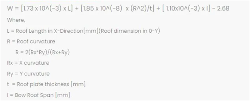
Judgement Condition : OK< 2.7> 3.1
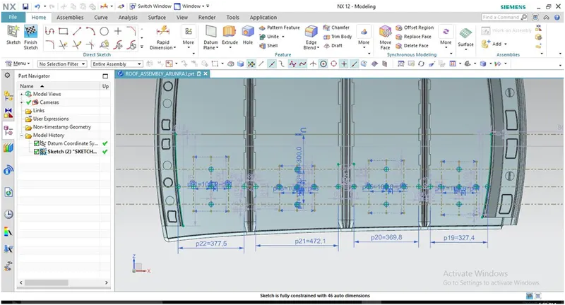
APPLY THE VALUES IN THE FORMULA:
In order to find the heat distortion apply all the necessary values from the roof to the give formula.
CALCULATIONS:

From the above table it can be concluded that all values of w<2.7 and also not w>3.1 so thus infers that current positioning of bow row are good in state as per design and found ok.
b. SNOW LOAD CRITERIA:
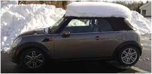
This test is done to know how the roof is behaving when there is a snow over. Normally due to the snow weight the dent will happen. But the roof should be designed in such a way that when the snow is removal the roof should go it its original position. This is the basic requirements for snow load criteria.
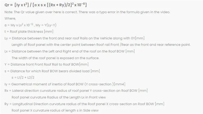
Judgment condition = Qr ≥ 3.1
250 ≤ s ≤ 380
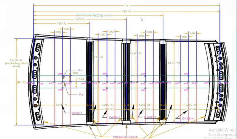
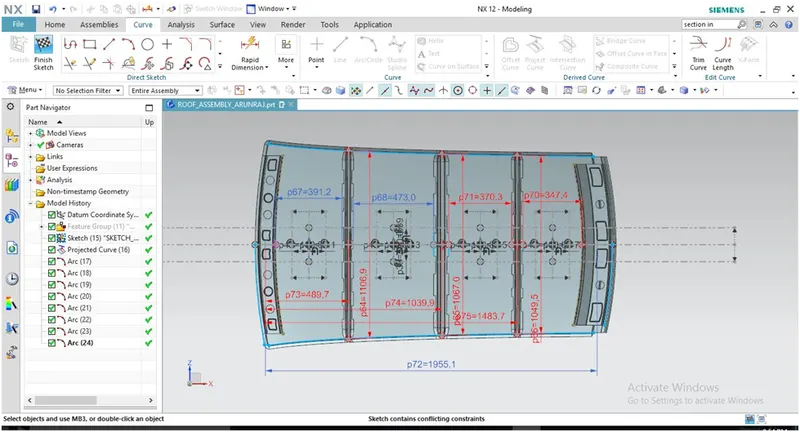
APPLY THE VALUES IN THE FORMULA:
In order to find the snow load criteria apply all the necessary values from the roof to the given formula,
CALCULATIONS:

It is observed from the values that are not obtained values of QR > 3.1. so we have to alter the design by
- Increasing the cross-sectional area of Roof rails so the Moment of Inertia also increases.
- Adjusting the distance of roof rails.
- Increasing the number of roof rails.
- Providing the Emboss on the roof top panel.
SECTION ANALYSIS:
Section moment of inertia is used to predict the amount of deformation and deflection of a part. A higher moment of inertia is preferable as it reduces the amount of deflection for a given force. The thickness of the part and addition of flanges and embosses increase the section inertia of the part. Here the master sections of the roof and roof rails and their section analysis are given.
1. FRONT ROOF RAIL:
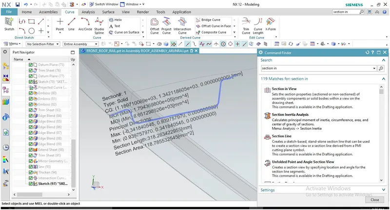
Moment of inertia maximum, (MAX) I = 1.7943X10⁵(mm4)
Moment of inertia maximum, (MIN) I = 8.6512X10³ (mm4)
2. BOW ROOF 1:
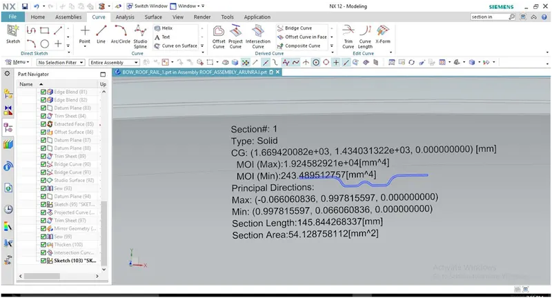
Moment of inertia maximum, (MAX) I = 1.9245X10⁴ (mm4)
Moment of inertia maximum, (MIN) I = 243.4895(mm4)
3. CENTRAL ROOF RAIL:
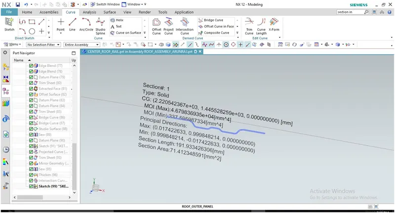
Moment of inertia maximum, (MAX) I = 4.6798 X10⁴ (mm4)
Moment of inertia maximum, (MIN) I = 337.5959(mm4)
4. BOW ROOF 2:
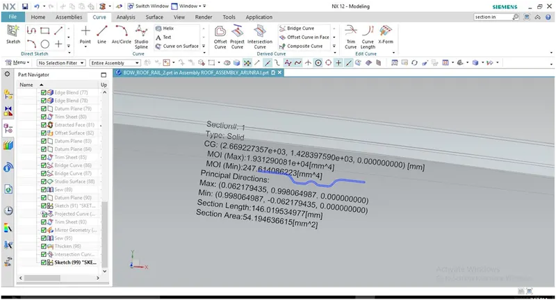
Moment of inertia maximum, (MAX) I = 1.9312X10⁴ (mm4)
Moment of inertia maximum, (MIN) I = 247.6140(mm4)
5. REAR ROOF RAIL:
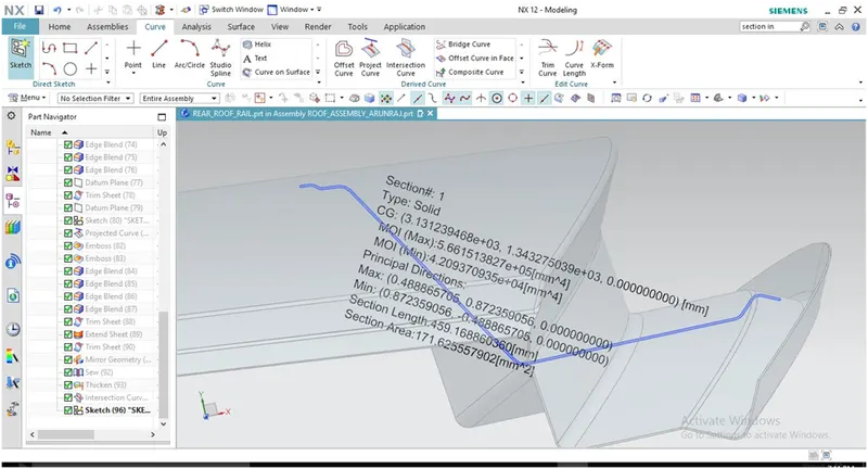
Moment of inertia maximum, (MAX) I = 5.6615X10⁵ (mm4)
Moment of inertia maximum, (MIN) I = 4.2093X10⁴ (mm4)
DRAFT ANALYSIS:
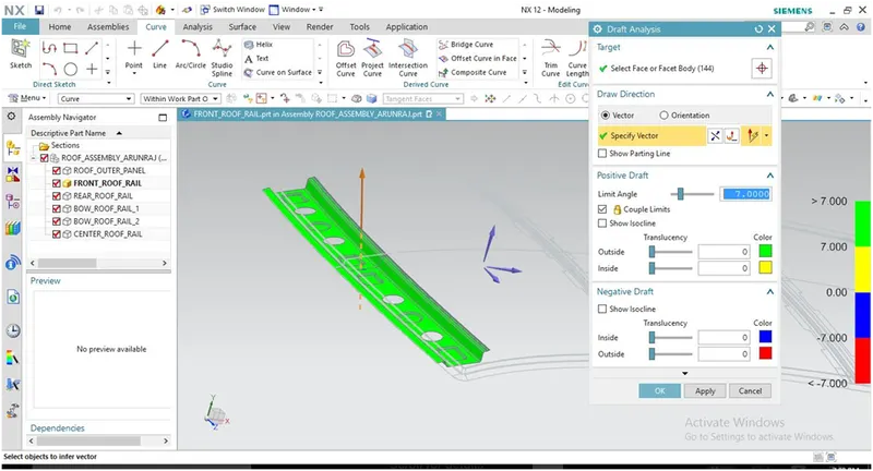
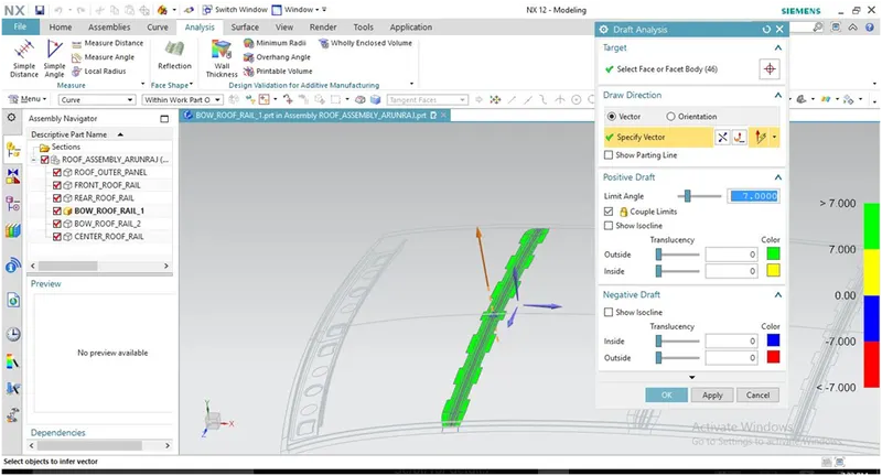
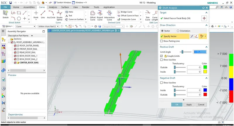
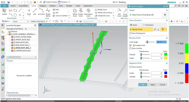
The Draft Analysis command enables you to detect if the part you drafted will be easily removed. This type of analysis is performed based on color ranges identifying zones on the analyzed element where the deviation from the draft direction at any point, corresponds to specified values.
Minimum draft angle of 7° is considered for analysis. green color infer on the parts that all face along the tooling direction has positive draft angle greater than 7° and passed in analysis.
- DRAFT ANALYSIS FOR FRONT ROOF RAIL:
- DRAFT ANALYSIS FOR ROOF RAIL 1:
- DRAFT ANALYSIS FOR CENTER ROOF RAIL:
- DRAFT ANALYSIS FOR ROOF RAIL 2:
- DRAFT ANALYSIS FOR REAR ROOF RAIL:
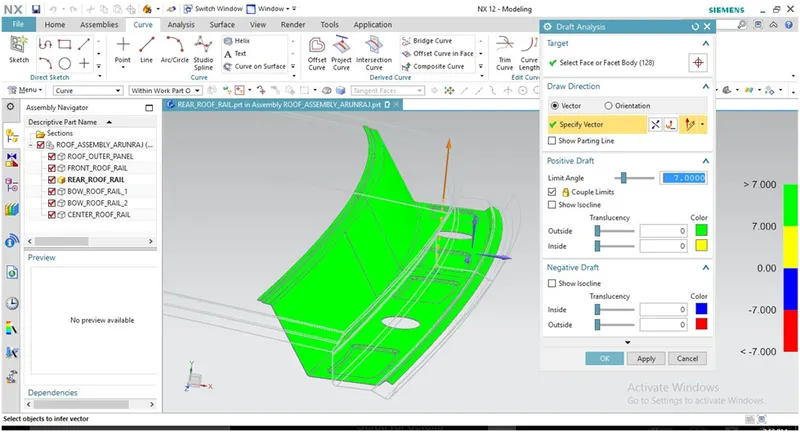
- DRAFT ANALYSIS FOR REAR ROOF OUTER PANEL:
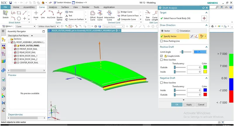
Some portions of outer panel are nor satisfying draft angle because of complication at the edges so may be the rear part can bended individually and attached to the main roof sheet to overcome the draft angle issue and the top portion of roof is stamped easily.
CONCLUSION:
Hence the roof, front roof rail, bow roof rails, central roof rail and the rear roof rail is designed by following the master sections and the moment of inertia and draft analysis are carried out to check feasibility manufacturing.
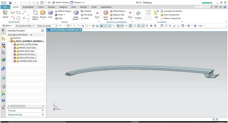
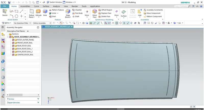
SCREENSHOTS OF DIFFERENT VIEWS: