Week 9 - Project - A pillar Design with Master Section
A Pillar design with Master Section
Aim: To create A pillar Design with given Master Section.
Objectives:
- Creation of Tooling axis with appropriate draft analysis for given A class surface and master section.
- Creation of B class and C Class surfaces for creating a solid component.
- Creation of attachment features like Dog house.
- Performing final draft analysis and creating final product.
Draft analysis for Class A Surface:
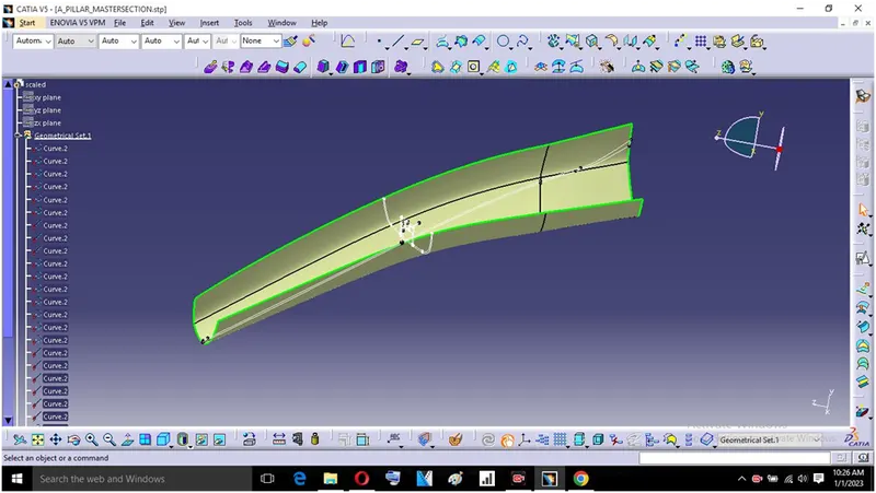
After creating Tooling axis we do draft analysis, Before drafting we have to make sure that in view mode it is selected for the materials.
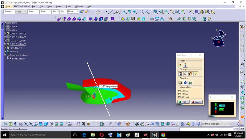
After selecting the feature draft analysis tool we drag the compass from its position to the tool axis. Then lock the compass, After that select anywhere on the component and it will give the result.
We change the angle to 2.9°.
Creation of Class B Surface:
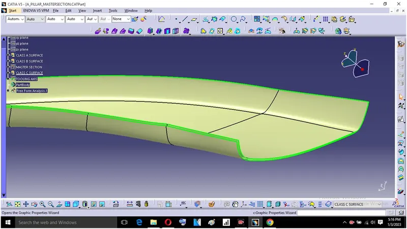
While creating the Class B surface first we have to offset the Class A surface for 2.5mm distance outward by referring master section then some the surfaces gives offset error and asks for offset without error surfaces and work on incomplete surfaces by using multi section and other commands to complete the class B surface.
Creation of Class C Surface:
To create Class C surface first we have to extract the edges from the class A surface with the help of multiple extract or boundary command in which we create a path for sweep of Class C surface.
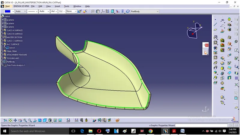
We have to create all separate sweeps and join them together. Once all the sweeps are joined we have to join Class C surface with Class A surface.
Then Trim the Class B surface with Class A+C surface this will make sure that we get a closed surface. We can check it by using boundary tool, if its gives error the component is not closed.
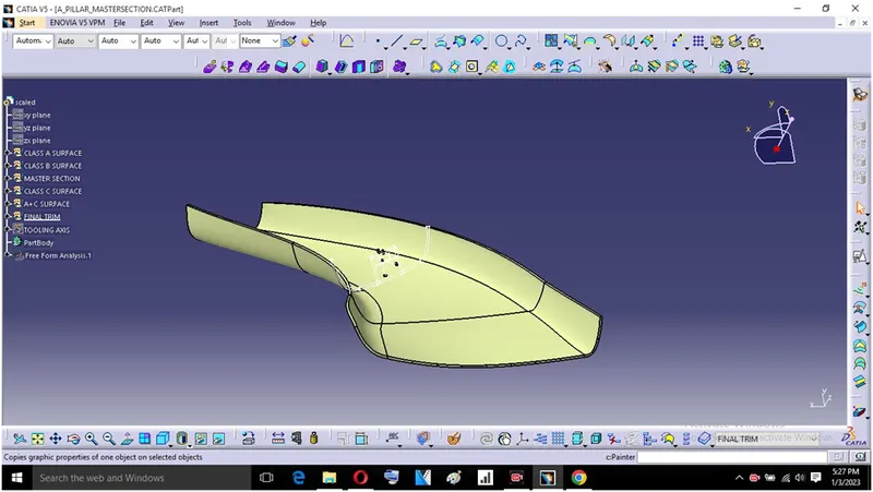
Then we go for part design workbench and use the closed surface tool to create a solidbody.
Creation of Doghouse:
Dog house is an engineering feature used in plastic trim design they are used as supporting features. Sometimes other features are used like snaps, locators, etc. they are mounted to increase the strength of the product.
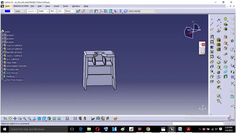
Steps for Dog house creation:
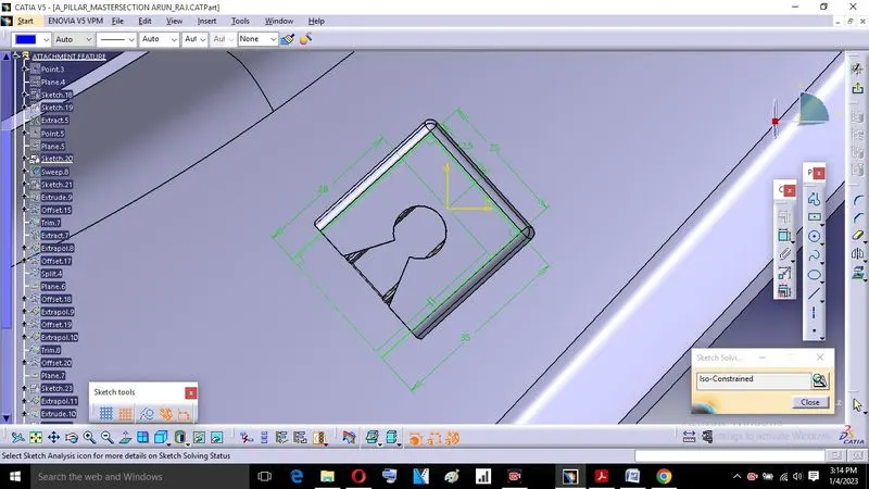
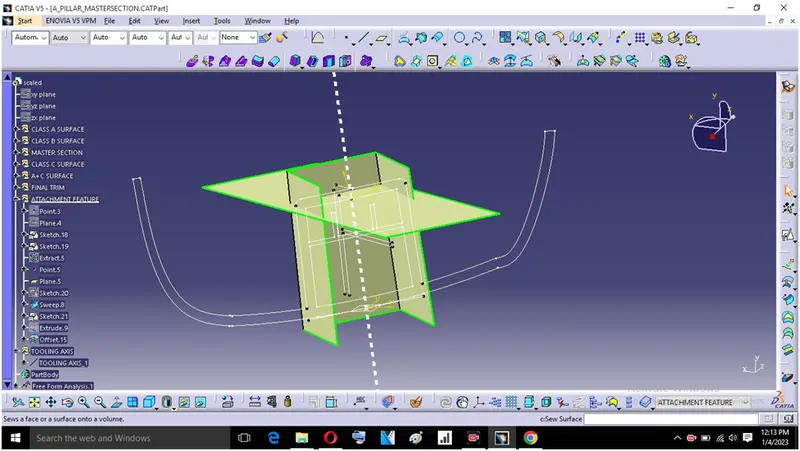
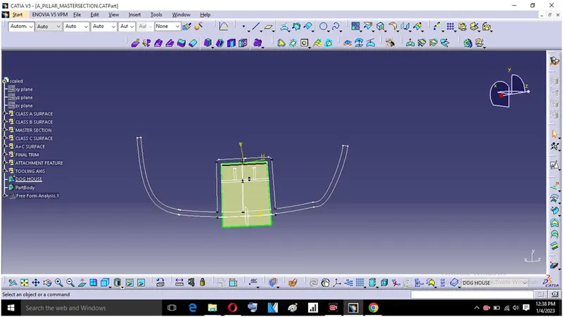
Extract the surface on which we want to create the doghouse and create a plane which is normal to that surface. Create the sketch on that plane using Positioned sketch (Refering mastersection for dimensions).
We create the closed upper surface of the dog house by using extrapolate, extrude, offset and trimming feature.
Draft analysis on Dog house:
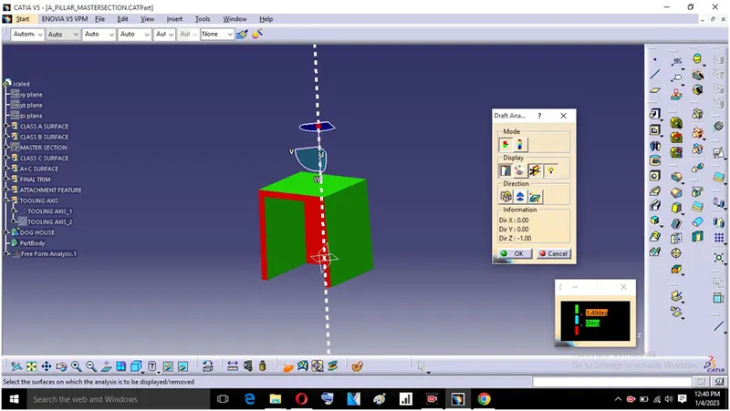
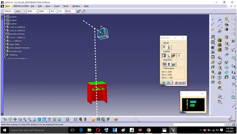
Before drafting we have to make sure that in view mode it is selected for the materials.
After selecting the feature draft analysis tool we drag the compass from its position to the tool axis. Then lock the compass, After that select anywhere on the component and it will give the result.
We change the angle to 1.5° to draft in the direction of main tooling axis and 0.5° for side core axis.
Draft analysis on final component:
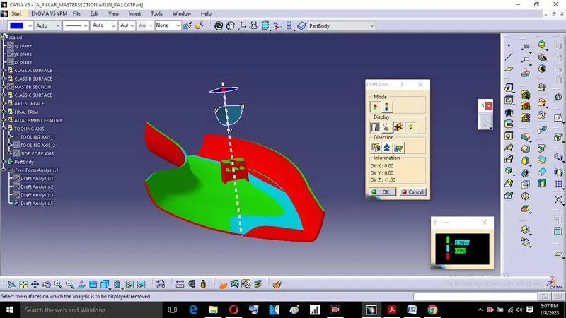
- The final part which is created is to be changed to the material mode.
- Compass is enabled and aligned it with the tooling axis.
- The lock command is applied to fix the compass with the tooling axis.
- Colour codes are applied and draft angle is defined as 2.9°.
- Running point analysis is used to get the permissible draft angle.
Conclusion:
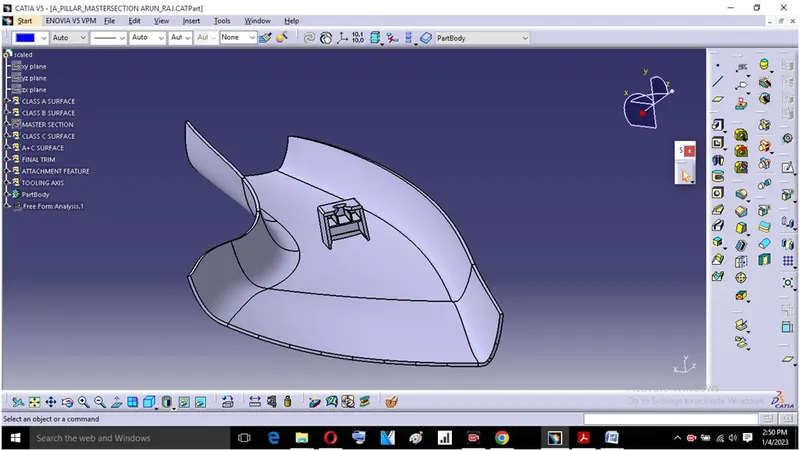
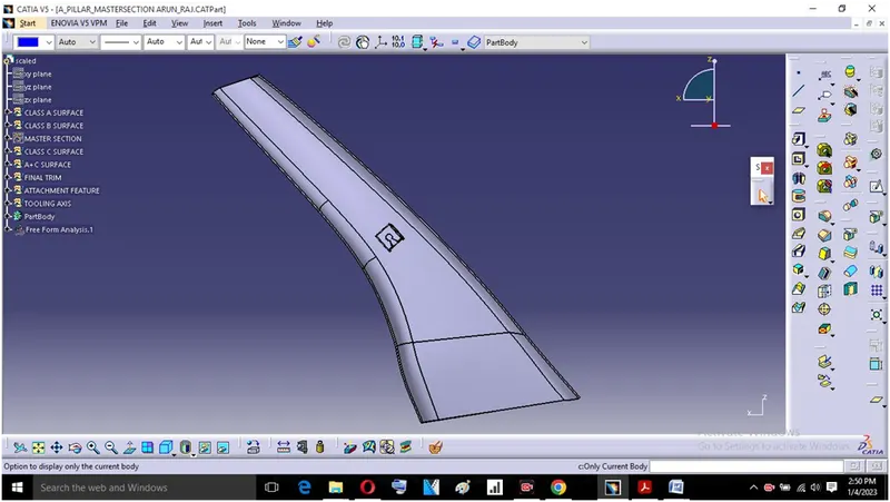
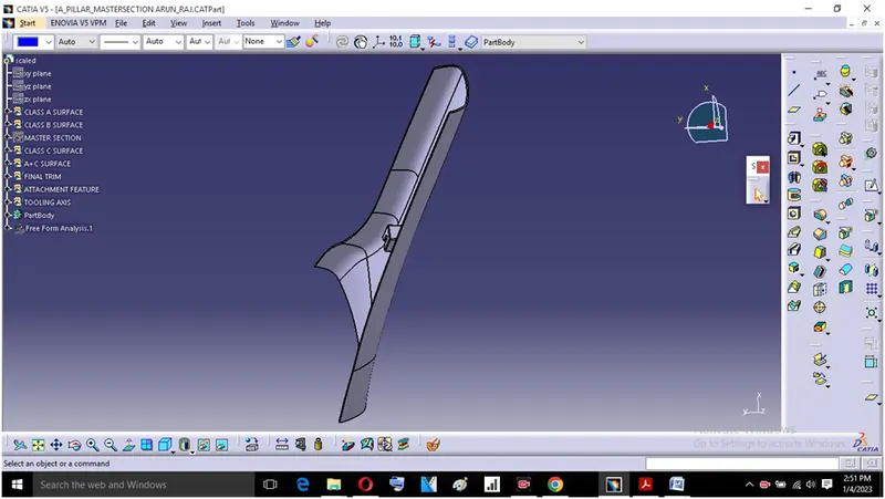
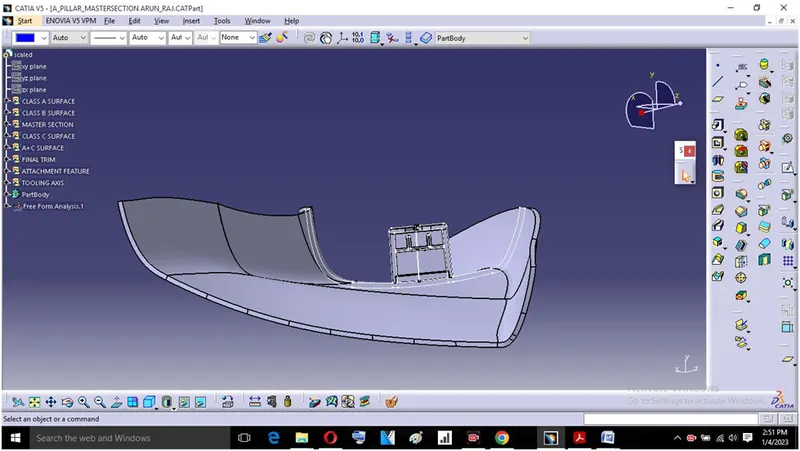
Hence, A pillar design is created from given matersection.
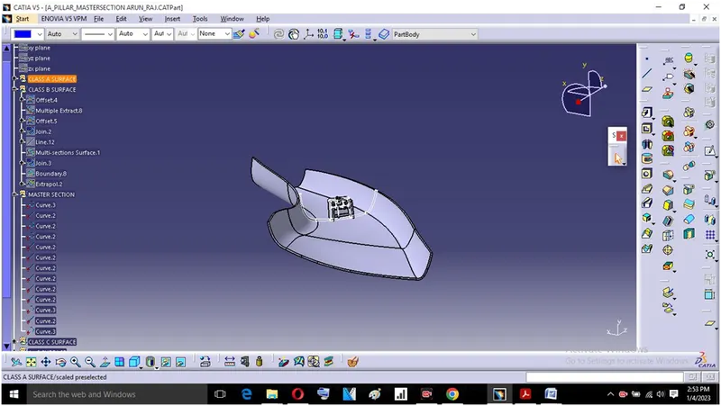
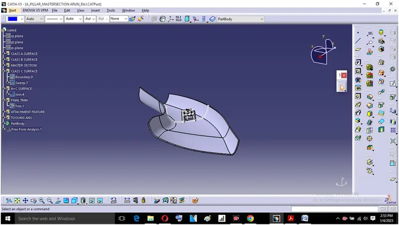
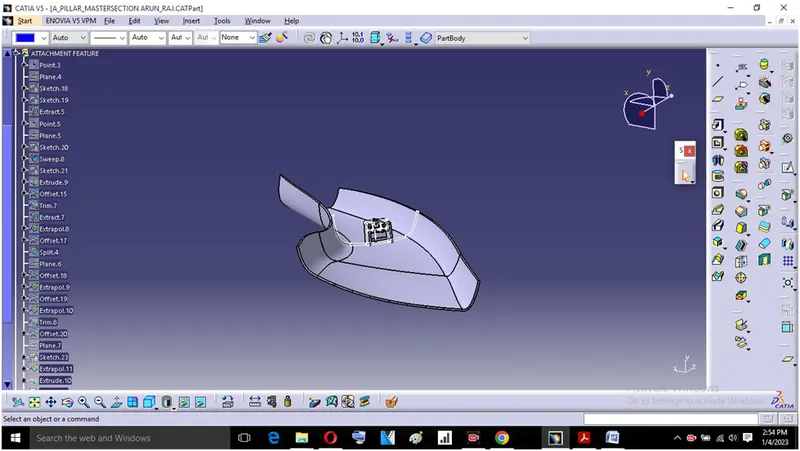
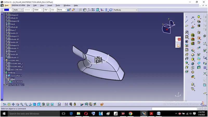
Screenshots of different views:
Screenshots of Feature tree: