Final Project: Electric Rickshaw modelling
Theory: Electric rickshaws (also known as electric tuk-tuks or e-rickshaws or toto or e-tricycles) have been becoming more popular in some cities since 2008 as an alternative to auto rickshaws and pulled rickshaws because of their low fuel cost, and less human effort compared to pulled rickshaws. They are being widely accepted as an alternative to petrol/diesel/CNG auto rickshaws. They are three-wheelers powered by an electric motor ranging from 650 to 1400 Watts. They are mostly manufactured in India and China, only a few other countries manufacture these vehicles. Battery-run rickshaws could be a low-emitter complementary transport for the low-income people, who suffer most from a lack of transport facility, if introduced in a systematic manner according to experts.
These rickshaws have a M.S(Mild Steel) tubular Chassis, consisting of three wheels with a differential mechanism at the rear wheels. The motor is brushless DC motor manufactured mostly in India and China. The electrical system used in Indian version is 48V and Bangladesh is 60V. The body design from most popular Chinese version is of very thin iron or aluminum sheets. Vehicles made in fiber are also popular because of their strength and durability, resulting in low maintenance, especially in India. Body design is varied from load carriers, passenger vehicles with no roof, to full body with windshield for drivers comfort. It consist of a controller unit.They are sold on the basis of voltage supplied and current output, also the number of MOSFET(metal oxide field effect transistors) used. The battery used is mostly lead acid battery with life of 6–12 months. Deep cycle batteries designed for electric vehicles are rarely used. Weight of the electric car has also been a recurring design difficulty in them.
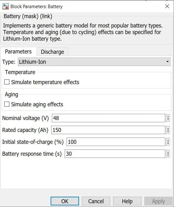
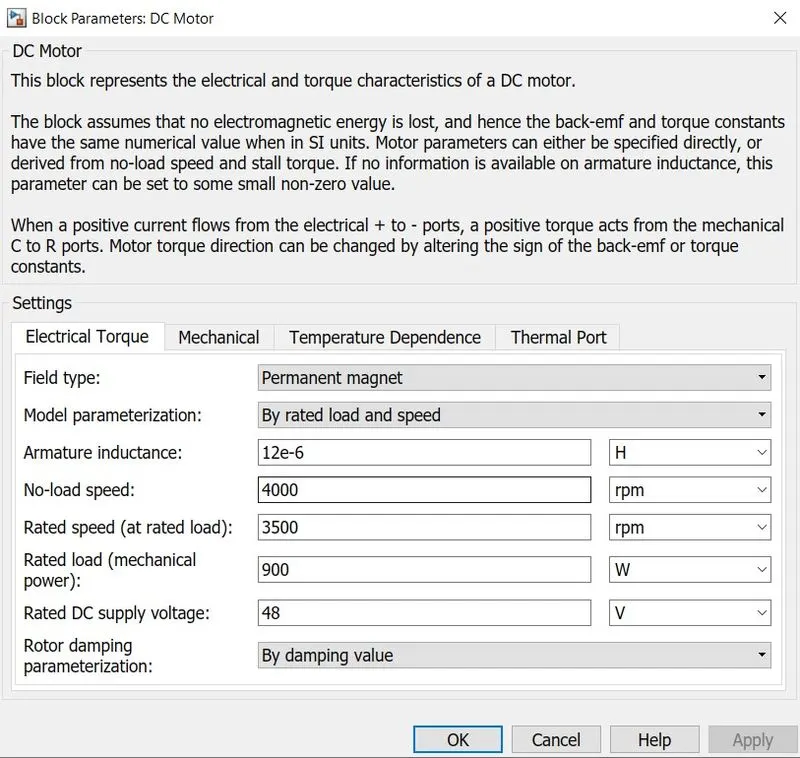
I have considered some assumptions from the data I got from some research papers. The motor considered is a 48V BLDC motor with rated load power of 900W at 3500 rpm and no load speed is 4000rpm. The battery considered is 48V battery with a rated capacity of 150Ah.
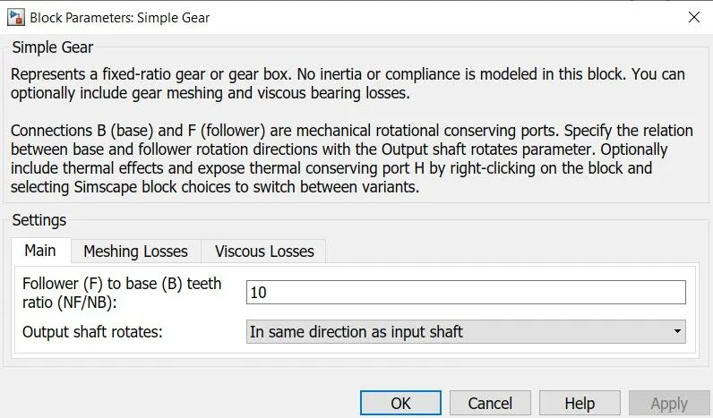
The final drive ratio is taken to be 10 and the tire considered is of 0.3m rolling radius similar to the ones used in Mahindra treo series. The model along with the other parameters assumed for the simulation are shown below.
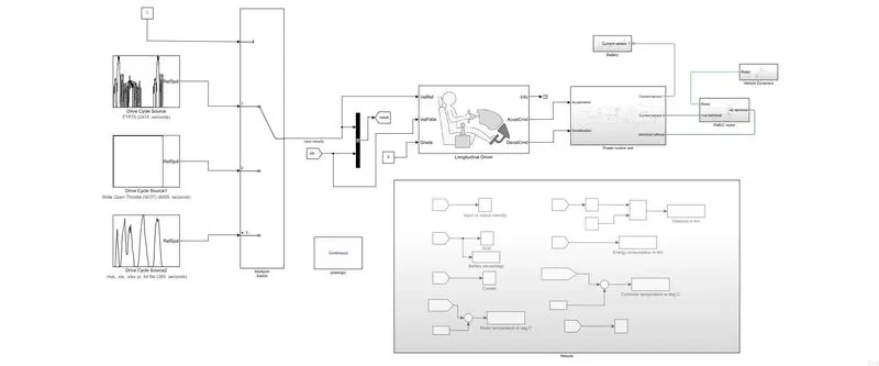
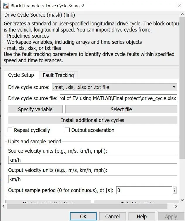
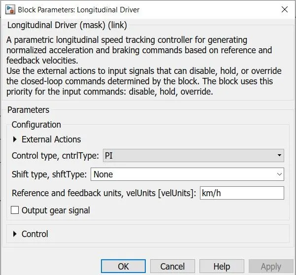
Firstly the three drive cycles are connected to a multiport switch and operated as per the constant value given. This data is input to the longitudinal driver block to obtain the acceleration and deceleration commands as per the reference voltage provided by the drive cycle. The block parameters of the longitudinal driver block is shown below.
The acceleration and deceleration commands are input to the power control unit subsystem, which is shown below, which converts the commands to operate the duty cycle of the motor voltage in order to vary the speed of the motor as per the reference.
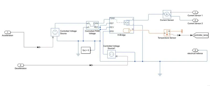
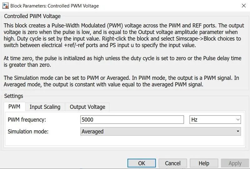
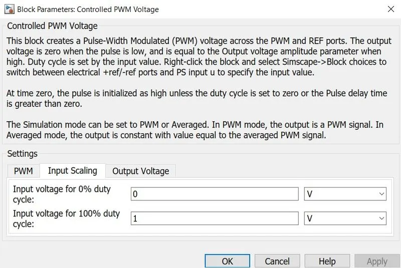
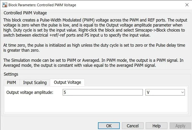
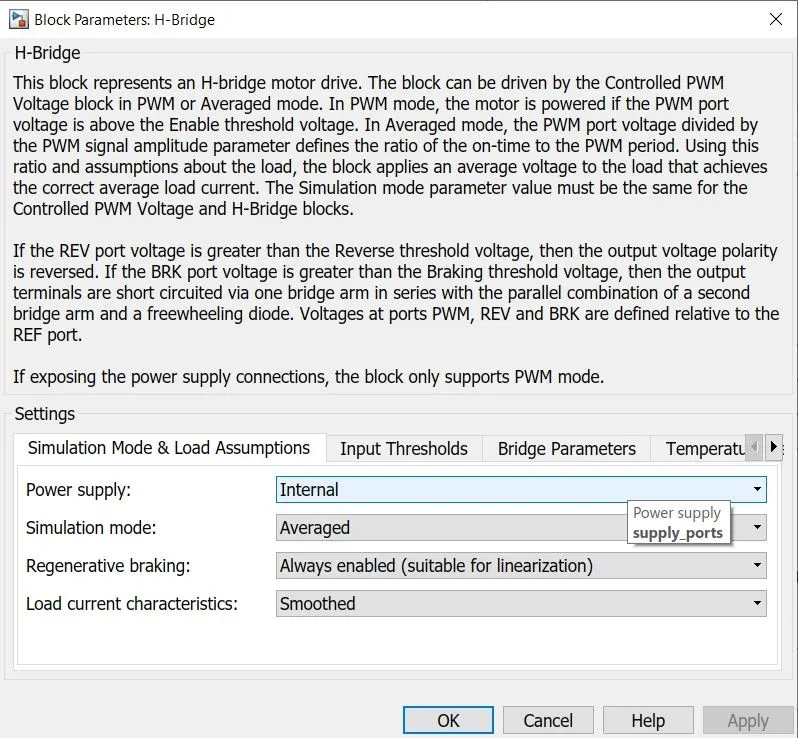
The power control unit subsytem consists of the controlled voltage source blocks, controlled PWM voltage block and H-bridge with sensors like current sensor block and temperature sensor to obtain the controller temperature which is connected to a goto block. This subsystem generates a PWM signal according to the duty cycle required to operate the motor. The parameters of different blocks used are shown below.
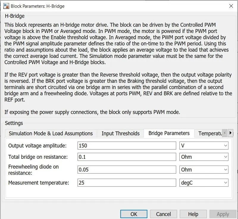
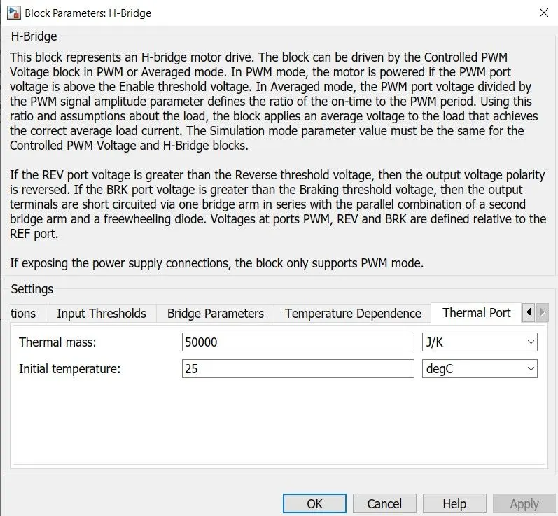
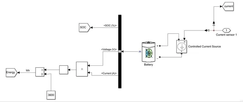
The current requirements as per the output voltage of the H-Bridge is used to calculate the energy requirement and SOC of the battery according to the battery parameters given in the battery block. The subsystem for the battery and related calculations is given below.
The battery block parameters are as shown below.
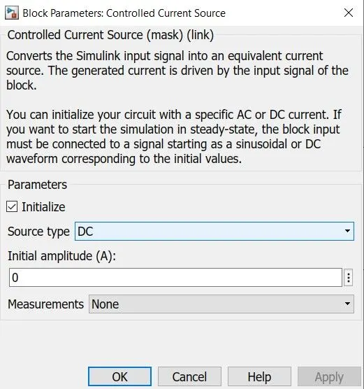
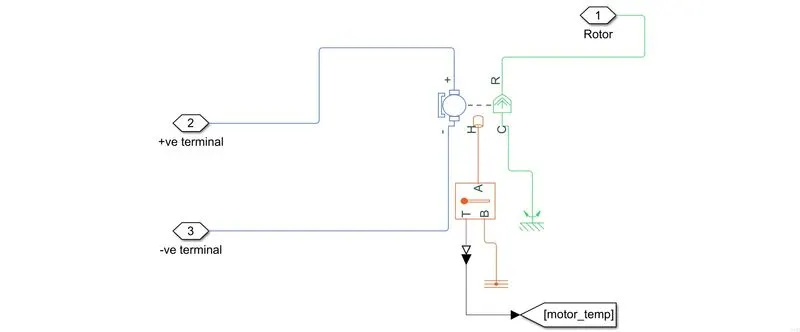
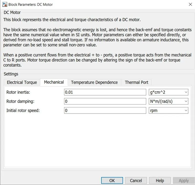
The output current from the power control unit subystem is given as input to the DC motor and the resulting torque and speed are given to the final drive simple gear block. The DC motor subsystem along with the DC motor block parameters are given below.
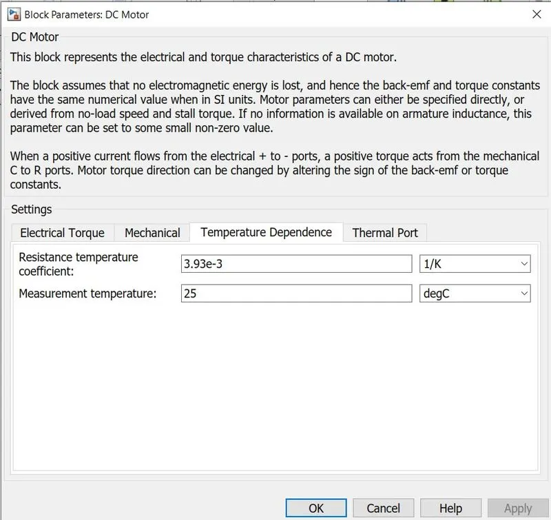
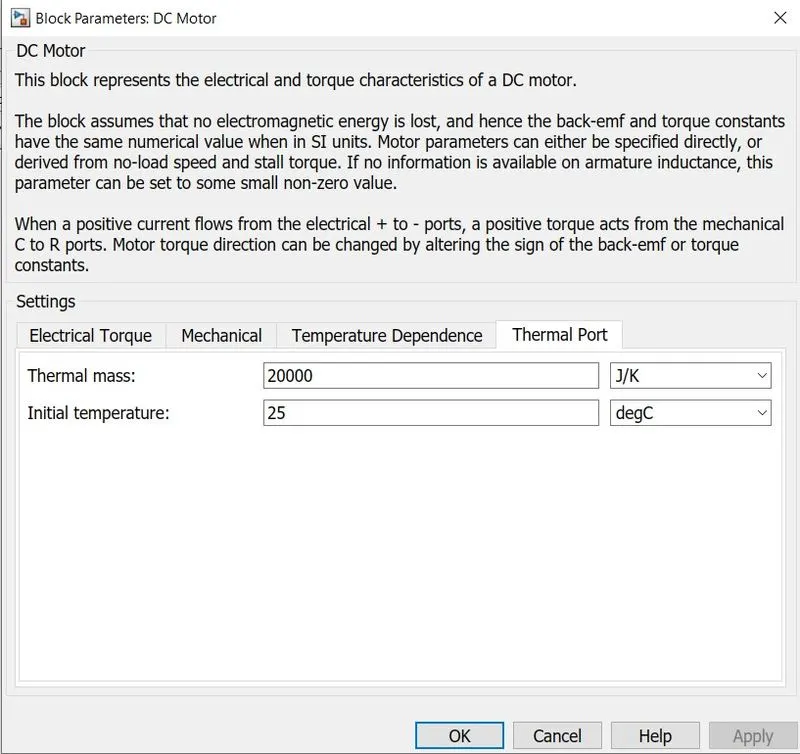
The rotor values are given as input to the vehicle dynamics subsystem which is as shown below.
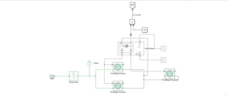
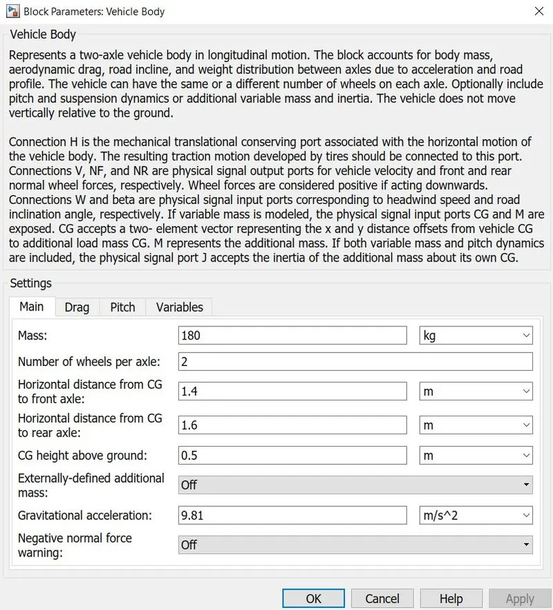
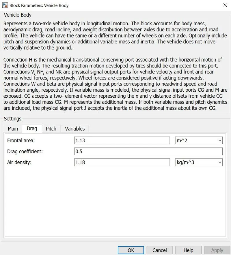
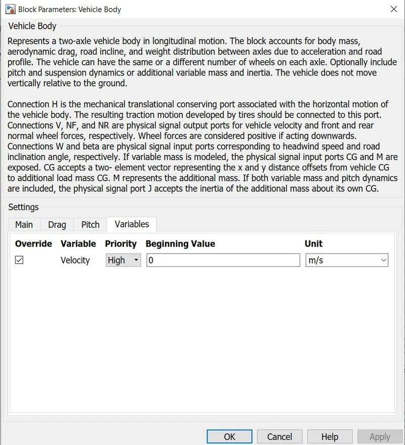
Here simple gear, inertia block, tire block and vehicle body block are used to get the final velocity of the body which is given to a goto block and used to analyze the results. The block parameters of all above mentioned blocks are given below.
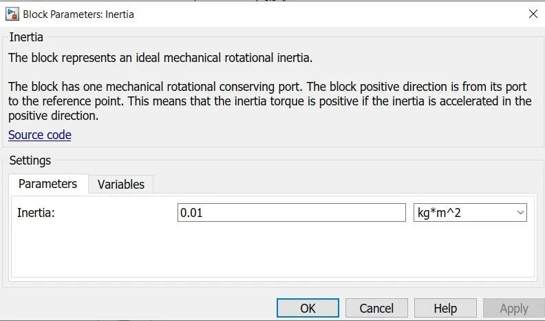
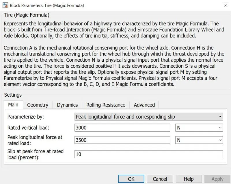
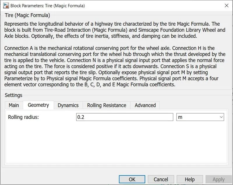
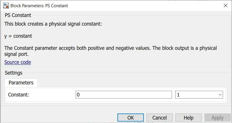
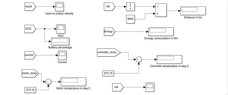
The results subsystem consists of all the scopes and displays to analyze the outputs of the whole system.
Results:
FTP75 drive cycle:

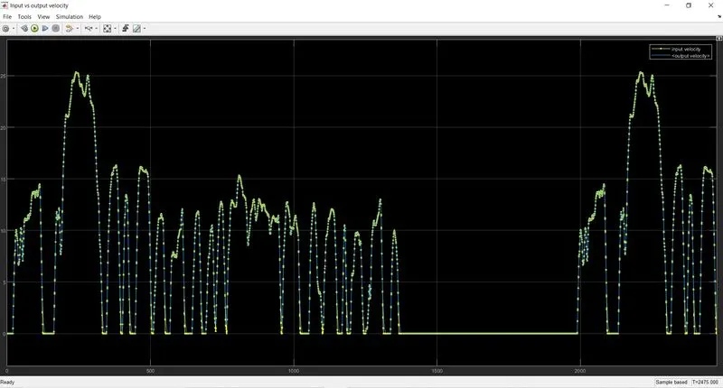
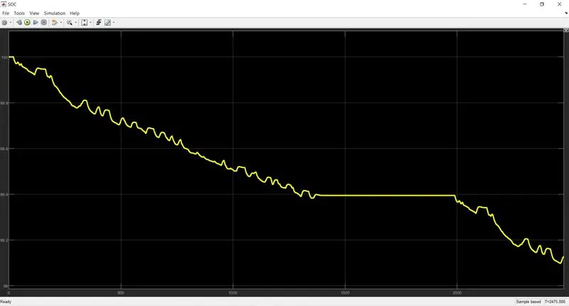
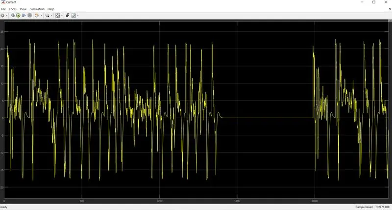
As we can see that the output velocity goes along the reference voltage and the SOC after the cycle is at 99.13% after one cycle. The motor temperature and the controller temperature are also in operating conditions( below 100 deg C). The current requirements were going upto 22A and the reverse current during breaking also fluctuates at peak of 18A where negative sign represents the charging condition. Here due to a higher capacity battery of 150Ah we are able to get longer range for the vehicle but this also increases the battery costs.
Constant velocity at 45kmph for 100km:
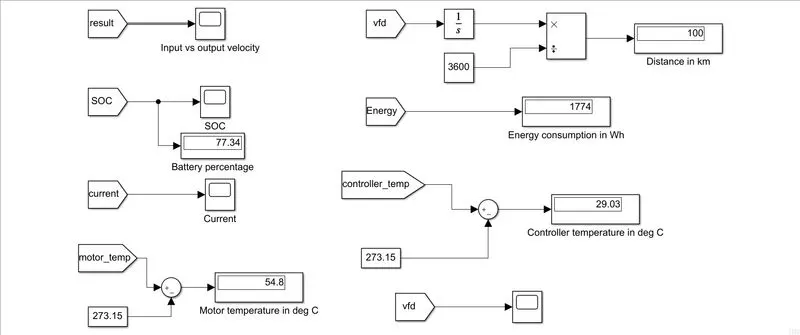
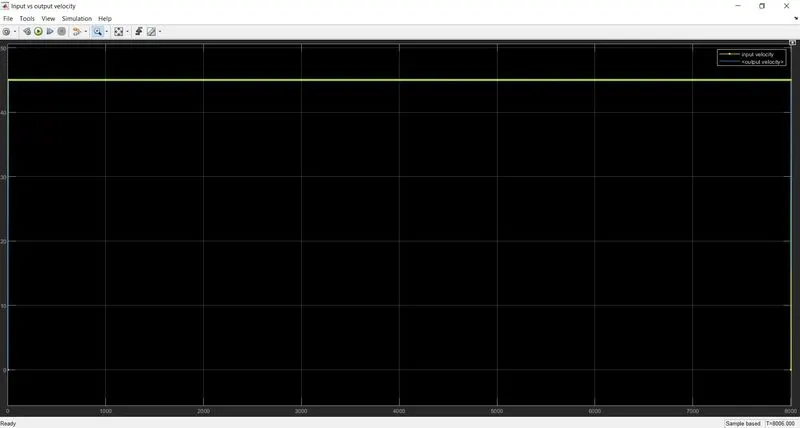
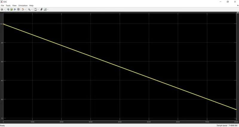
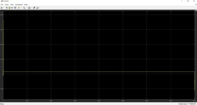
Here we can see that due to a constant velocity drive the current requirement is constant for almost all the time at 15A and the SOC decreases at a constant rate. Here due to prolonged used the motor temperature is seen to be higher than the previous case but still lies in the operating range of the motor and controller.
Customized drive cycle:
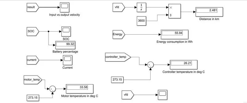
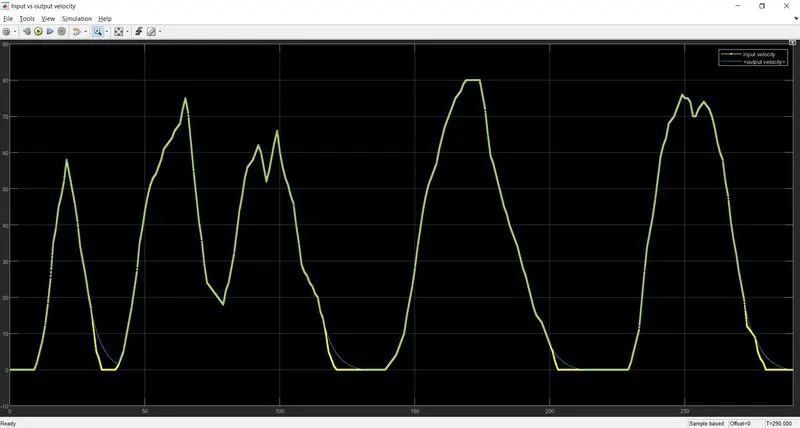
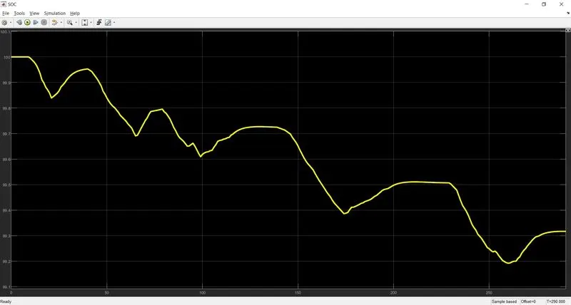
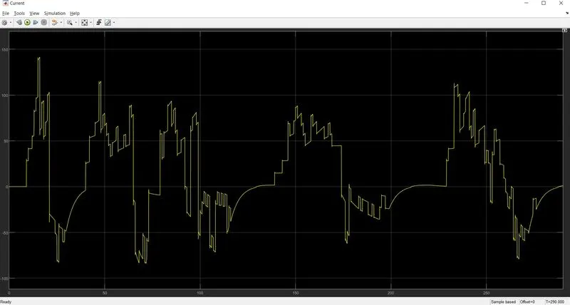
Here even when the time of simulation is less than FTP cycle the temperature of both motor and controller are higher than the FTP case. This is due to the fact that higher speed is demanded here and hence the current requirements are higher and this results in more heat generated.
Hence the model for electric 3- wheeler rickshaw was made and simulation was done for three different cycles. The same model is also attached below.