Week - 4 To model a stateflow chart for control logic of washing machine and gear shifting.
State flow: Stateflow is a control logic tool used to model reactive systems via state machines and flow charts within a Simulink model.
1.Objective: To implement control logic of a “washing machine” using Stateflow.
Procedure: A control logic is designed as per the given instructions and the flowchart for the same is shown below. Inputs of power supply and water supply are given through toggle switches. These inputs are used in the flow chart and the process is followed till the flow chart ends at finish. The power, water and finish block are taken as outputs to light the Lamp connected to it as signals. The water connected lamp is set to light when there is no water supply available. Power and finish are configured to light when they are on or when they return 1 as output.
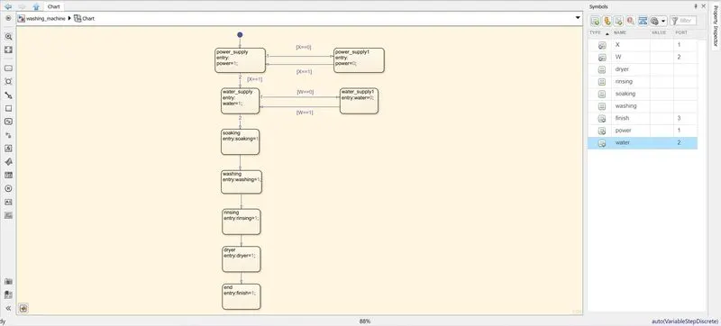
This flow chart is embedded in the simulink model and the program is run two times for different outputs which are shown below.
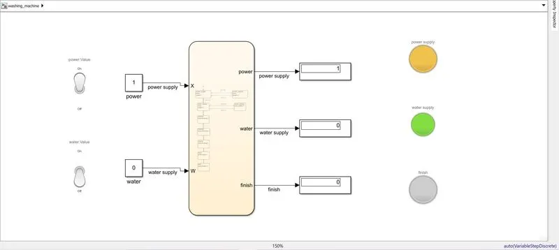
In the above case the power is turned on while the water is off and so both those lamps are turned on. Now the model is not able to move through the next step from water supply due to no water supply and hence the finish light doesn't glow up when the simulation is completed.
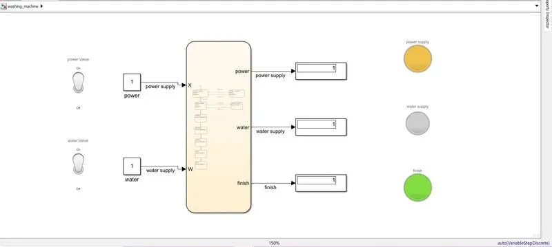
In this case both the power and water supply is turned on and hence the simulation after completing all the steps also lights the finish light indicating the process has ended.
Conclusion: A control logic of an automatic washing machine was implemented using stateflow.
3.Objective: To make a Simulink chart for the “Gear shift” logic.
Procedure: We can make the flow chart by simply making transitions in each state as per the speed. The speed is input into the chart using a dashboard slider. The top speed is kept at 100. The gear variable value is changed as per the speed and is given as output using display. The chart for the gear shift is shown below.
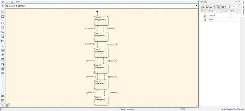
The model made for this simulation is as shown.
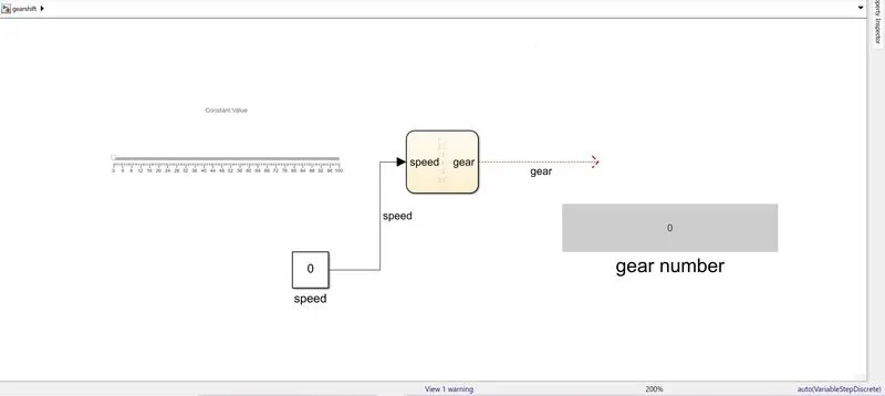
A graph acquired while run time ,while changing the speed values through the slider, is given below.
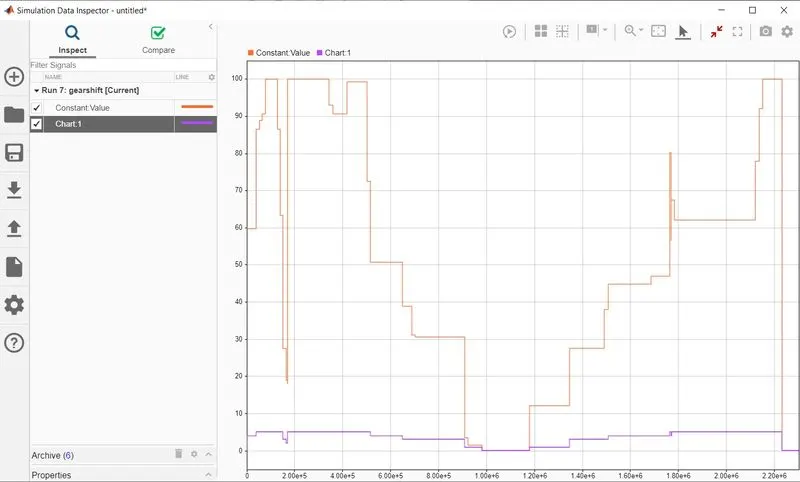
We can see the line depicting chart:1 value which are the gear values at that speed.
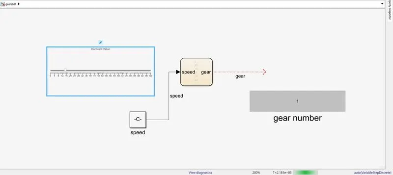
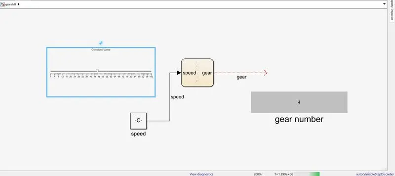
Different cases where the slider is placed at different speeds and the display for the gear value in the model are shown below.
Conclusion: The gear shift logic was implemented in simulink using stateflow.