2D meshing for sheet metal
AIM: To extract the mid surface and then mesh the component with given quality criteria parameters and assign the thickness on a hood component.
The hood model given consists of five different parts i.e., Hatch, left and right hinge, inner panel, outer panel.
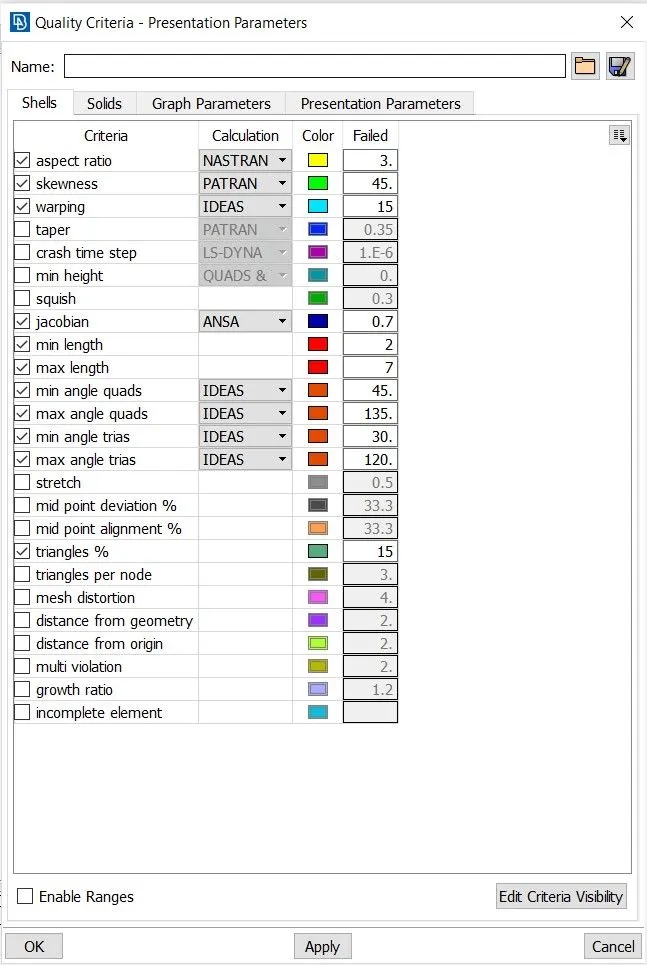
The main objective is, for the given Hood model, Take the mid surface for all the components after checking the geometrical errors and mesh the mid surface with the given element Quality criteria.
|
S.No |
Quality Criteria |
Value |
|
1 |
Target/Average length |
5 |
|
2 |
Minimum Length |
2 |
|
3 |
Maximum Length |
7 |
|
4 |
Aspect |
3 |
|
5 |
Warpage |
15 |
|
6 |
Skewness |
45 |
|
7 |
Jacobian |
0.7 |
|
8 |
Minimum Quad Angle |
45 |
|
9 |
Maximum Quad Angle |
135 |
|
10 |
Minimum Tria Angle |
30 |
|
11 |
Maximum Tria Angle |
120 |
|
12 |
Tria Percentage |
15 |
Procedure:
The hood model is opened in ANSA for 2D meshing using File>open and select the downloaded model.
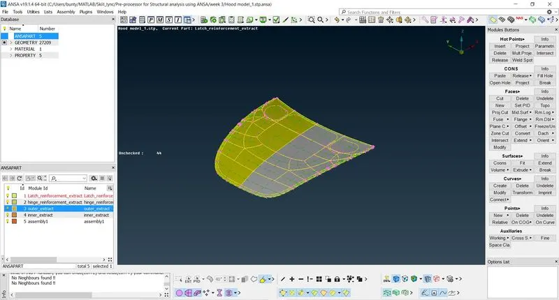
Select the different components separately using INOT command and then performing neighbouring all function to view a single component separately and lock and store this view. Similarly all the components are separately viewable in the lock views stored.
Increase the cons resolution by either the FINE option in the auxillaries modules buttons (or) by changing the mesh tabs perimeter module's LENGTH option on both the perimeter and macros to smaller size(say 1mm).
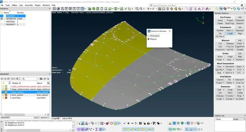
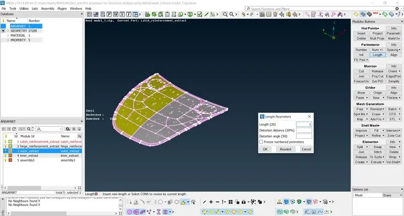
Using the ORIENT option orient all the faces such that when viewed in Entity mode entire side of the component should be in a single colour on one side(yellow or grey).
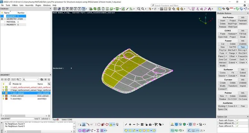
If any triple cons are present, then RELEASE option in the cons modules buttons can be used to remove the triple con and then a TOPO operation needs to be performed(as shown in above image) to stitch the two surfaces together, if required.
Then check for geometry using the checks manager and execute the geometry checks. If any errors are present solve by autofix or manually performing cleanup at the error area.
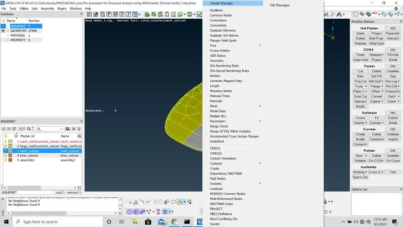
The checks manager option is shown above.
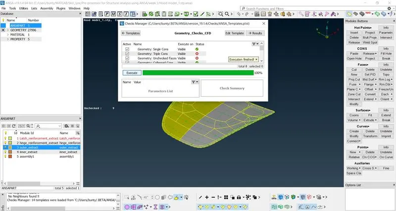
The geometry checks option is opened and executed.
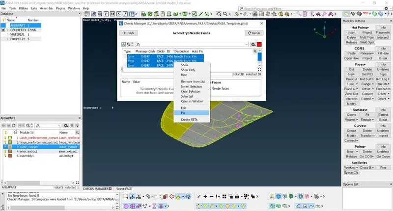
The errors shown are fixed using auto fix.
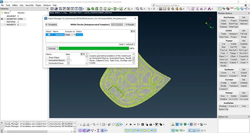
As shown there are no more geometry clean up required here.
Then the mid surfacing of the individual components are done either by directly using the MIDSURFACE option(skin option) (or) by creating offsets by OFFSET option for individual surfaces by manual selection under the faces module buttons. The offset needs to be done by measuring the thickness of the component and then making a offset towards the centre of the component for half the thickness. This will generate the mid surface for the component. The feature area tool can be selected for selecting the component surface for mid surfacing through the offset option. After the mid surface is ready, check for orientation and geometry of the midsurface created.
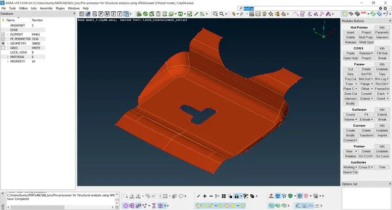
Then set PID for the mid surface through the SET PID option under the faces module and select the midsurface element and middle click to confirm the selection. Create a new Pshell PID for this midsurface with the thickness as of the original component and double click the PID to apply it to the midsurface.
Next go to the mesh window and under the perimeters module select the LENGTH option and then select the perimeters and select the component and set the length as required for mesh. After this check the whole geometry for inconsistency from the desired length over the perimeter of the object.
Also change the orientation of the holes in the model so as the sides are parallel to the neighbouring side. This can be done by SLIDE option under perimeters module. After sliding make sure to mark the nodes by selecting the MARK/UN option. Also make the number of nodes on the opposite faces and even on holes be same for best results.
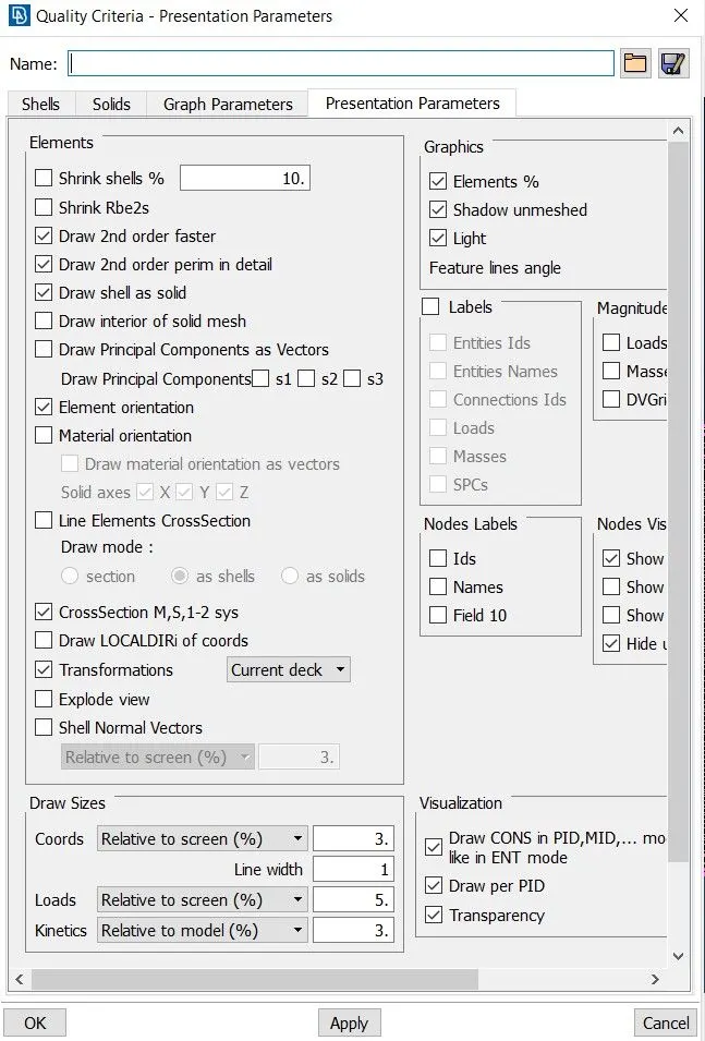
Next before meshing we need to check the Quality criteria(F11) where we need to select the qualities required and change the paramters as required in the question and under the presentation parameters tab check mark the 'elements%' under graphics and also keep the detail on demand effect to all details.
Then go to mesh parameters tab and set target length as the required mesh length with a range and also keep the mesh type to 'general' for normal meshing. Keep the elements type as required(mixed).
Then select BEST option under the mesh generation module and select the surface(s) for which we need to perform mesh. This mesh quality can be checked in the hidden view of the model. All the qualities should be met i.e., OFF paramter shown at the left should be zero.
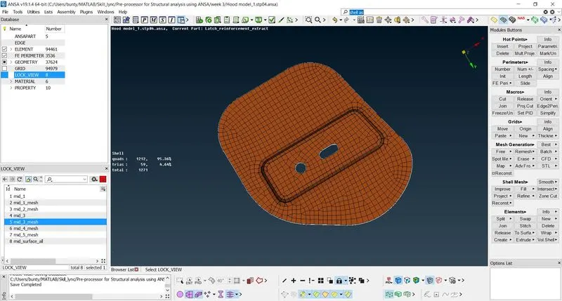
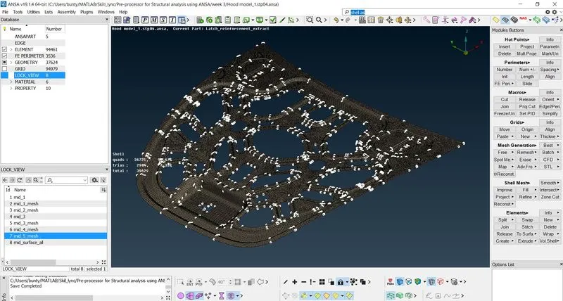
The meshing is improved through the RECONSTRUCTION option and SMOOTH option under the shell mesh module. The elements failing for the Qualiy criteria are seen here and rectified. Also using the SPLIT, JOIN options under the elements module are used to remove the trias if possible. The surface can be cut into smaller portion and then meshing can be done to improve the mesh quality. When doing this, JOIN option under the macros module needs to be used to join these cuts made after the meshing is done and then SMOOTH operation is performed to smoothen out the mesh generated.
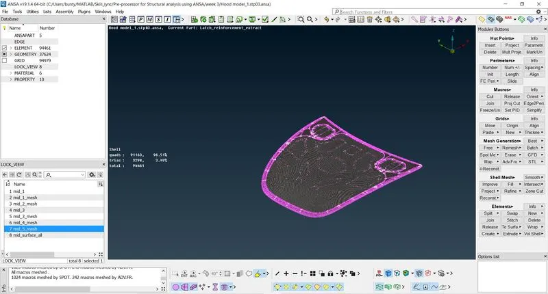
The complete meshed model is as shown above. After this we need to go to the quality criteria again and under the elements options under the Presentation parameters check mark on the draw shell as solid to convert this 2D mesh into 3D by applying the thickness as mentioned in the PID values for each.
The FE model can be separated from the geometry by the RELEASE option under elements module. The FE model separately can be seen as shown below.
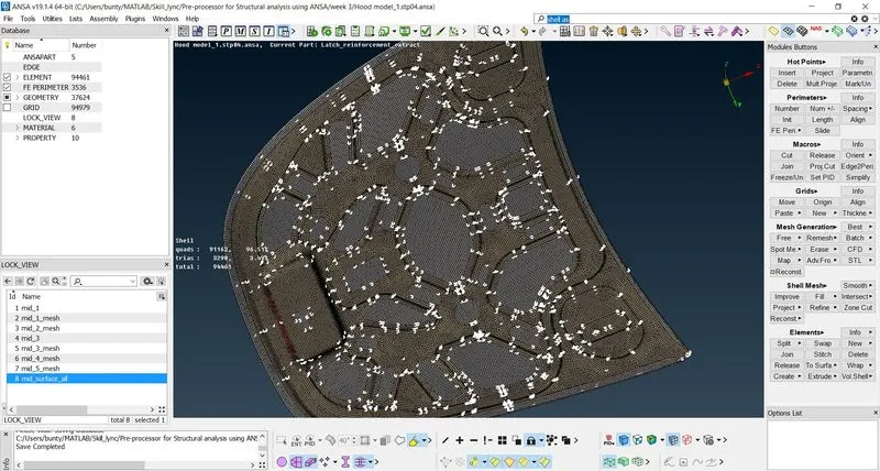
The model meshed is attached below.
Results: The mesh is obtained for the given model and the mesh parameters are shown as trias % of 3.49%. The whole mesh model is obtained and ready for the boundary conditions and analysis.
Learning Outcomes:
- Application of several tools that are part of ANSA.
- Understanding geometry cleanup and other geometrical tools like TOPO.
- Understanding of midsurface generation of a component.
- Understanding meshing techniques, quality criteria and mesh improvement methods.
Conclusion: The hood component given is mid surfaced and the thickness is assigned as of the parent object and meshing is done as per the given quality criteria parameters.