Bird Strike - Project - 2
Bird Strike - Project - 2
Background:
Bird strikes and bird ingestion events are a significant concern in the aviation industry, occurring approximately once every 2,000 flights in the USA alone, as estimated by the Federal Aviation Administration (FAA). Which, leads to significant monetary losses in the form of repairs, delays and canceled flights
During flight, bird collisions can cause severe damage to multiple components located in the front of the plane, such as engine fan blades, windshields, forward fuselage and even on the leading edge of the wing and empennages
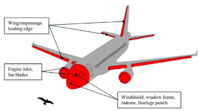
Therefore, multiple aviation authorities such as the FAA, the Federal Aviation Regulations (FAR), the European Joint Aviation Regulations (JAR) and the European Aviation Safety Agency (EASA) have implemented several requirements for forward facing aircraft components to posses a certain level of "bird strike resistance". This can be achieved through optimized designs, appropriate material selection techniques, and comprehensive testing
FEA engineers play a crucial role in the early-stage development of these components, their contributions include optimized designs, materials and reduced need for physical testing, which results in reduced potential incidents and mitigated financial and operational impacts caused by bird impact events
Procedure
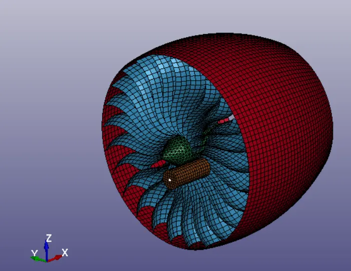
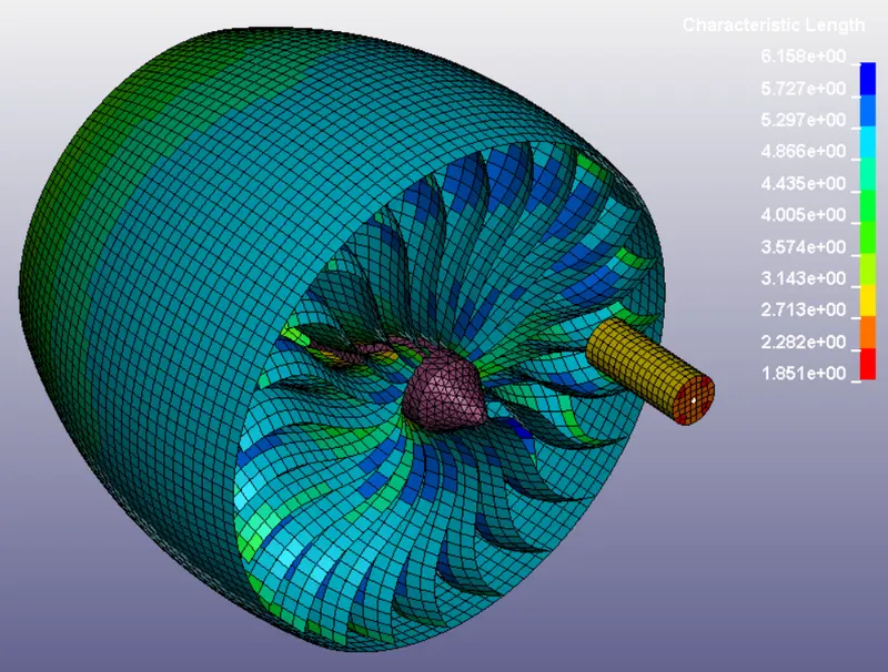
A bird strike collision event can be classified as a nonlinear transient dynamic problem. For this simulation, we will only consider the interaction between the engine casing, rotor blades, engine hub and a dummy bird which will be represented as a cylinder. All of these components can be observed in the following figure
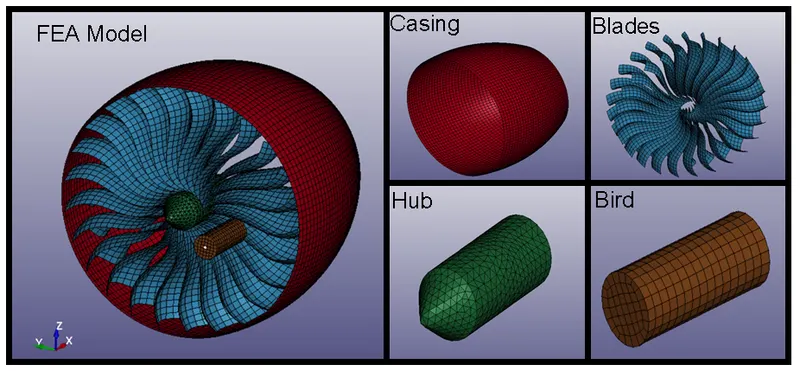
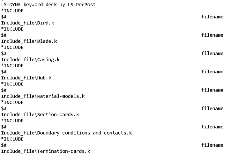
All of the parts in the FEA model are arranged into several .k files that will be referenced in the main file. From there, a different .k file will contain all the materials, and a separate one all the part sections, and two extra ones will contain the boundary conditions and termination cards
Material file
Starting by the material .k file, the engine blades and the hub will be modeled using Aluminum 4495 and a elastic-plastic material model (MAT024), which requires a true stress vs effective plastic strain curve as input
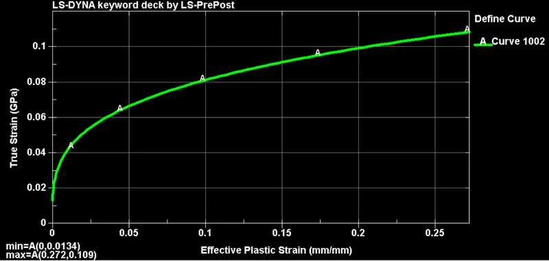
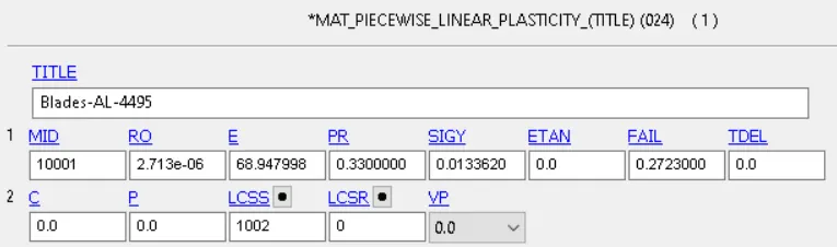
The engine casting will be modeled using a linear elastic material model (MAT001) of steel
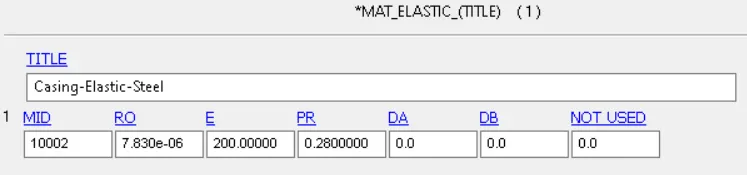
Lastly, the bird will also be modeled as linear elastic material from a soft body. Although, more complex approach's could include multi-modeling of the bird and even SPH (Smooth Particle Hydrodynamics) techniques
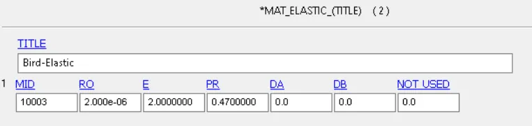
It's worth mentioning that the unit system for all the files will be Kg/mm/ms
Section Properties file
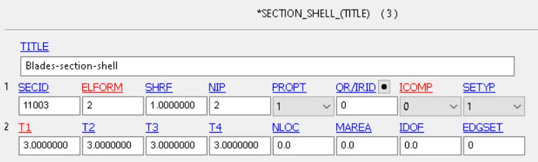
In terms of section properties, the engine casing, the blades and the bird are modeled with 2D elements. So a Section Shell keyword with different thicknesses is used for each of them. For this first case, the default element formulation (2) is used, although 16 or -16 can also be used at the expense of computational resources
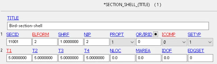
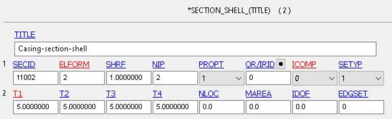
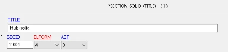
Lastly, the hub is modeled as solid elements and therefore a section solid keyword with element formulation 10 is used
Main file Creation and Include Keyword
In order to create the remaining .k files that include contacts, boundary conditions and termination cards, we must first create the main file and include them as blank files
After including all the files we obtain the same FEA model as in the beginning, yet, we can now modify each file individually and thus improving the work flow of the simulation
We can also start assigning both the material and section properties to each part using the keyword manager
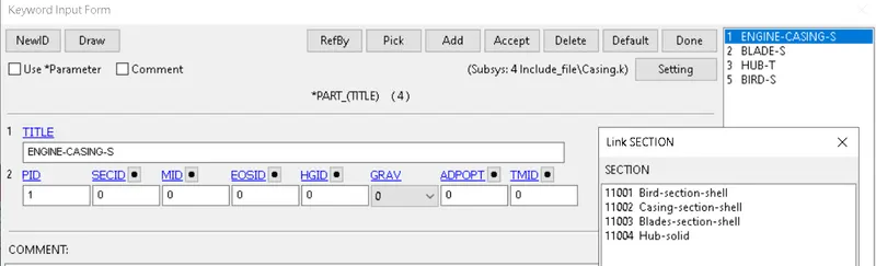
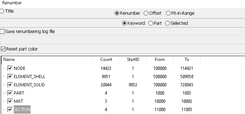
At this stage, we will also use the renumber menu to avoid duplicate nodes, part or material Ids
- Nodes will be renumbered starting from 100,000
- Shell Elements will be renumbered starting from 500,000, and solid elements from 700,000
- Parts will be renumbered starting from 1,000
- Materials will be renumbered starting from 10,000
- Sections will be renumbered starting from 11,000
Contact definition
Contacts are needed in the model in order to specify the relationship between the parts during the simulation. In this case, we need to define the following set of contacts:
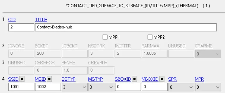
- Contact between the engine rotor blades and the hub. Since this surfaces must always be together we will consider a tied contact definition
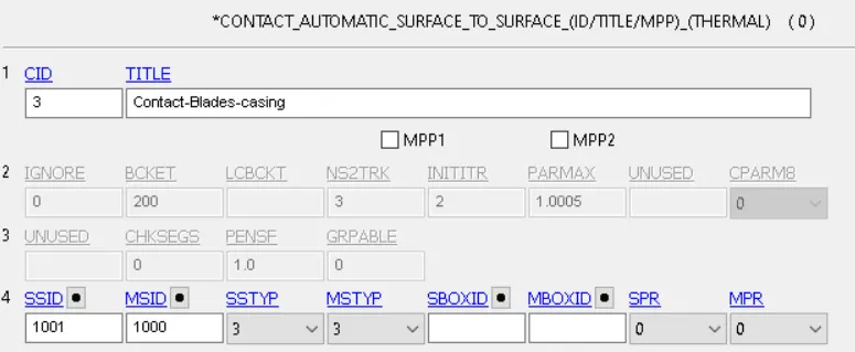
- Contact between the blades and the casing, since this components could potentially become in contact after impact we will use an automatic surface to surface contact definition
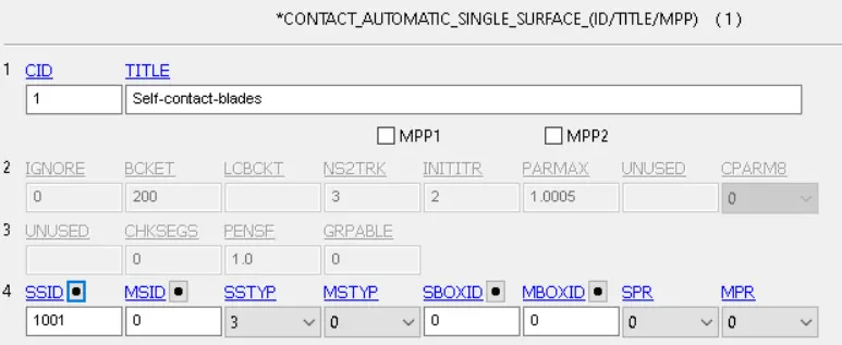
- Automatic single surface contact for the blades, since they can become in contact with themselves during the impact
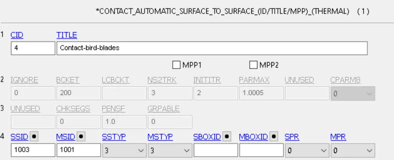
- Contact between the bird and the engine blades, since otherwise the bird would pass through the model
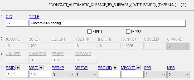
- Contact between the bird and the casing, since it may occur that after impact the bird passes through the blades and impacts on the casing or the hub
Boundary Conditions
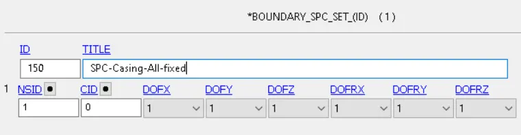
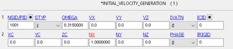
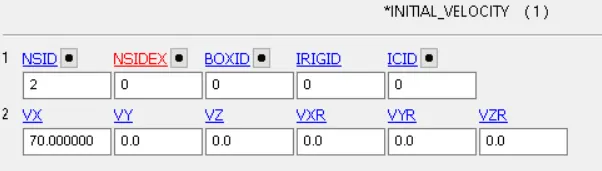
The boundary conditions for the model are relatively simple. The casing will be fixed in all DOF's, while the blades and hub share an initial angular velocity in the X axis. Lastly, the bird will be assigned to have a initial translational velocity in the same axis
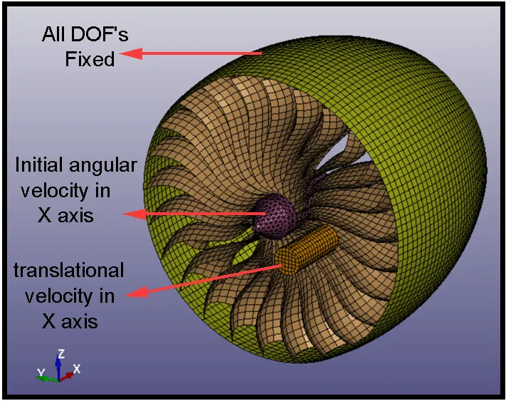
- SPC keyword for casing
- The angular velocity has to be converted from RPM (3,000) to rad/ms
- Bird translational speed of 70 m/s
Control termination file
This file consists on the specification of the simulation time (1.5 ms), time step definition and outputs in form of D3PLOT and ASCII files.
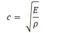
Ls-Dyna can calculate the critical time step automatically using both material properties and the characteristic length of the smallest element (1.851mm)

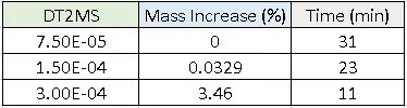
Yet, we will use a control time step keyword and play with the DT2MS parameter so that we increase mass up to 5% in the model to decrease computational time. The estimated time and the mass increase obtain in each step are shown in the following table:
Simulation Results
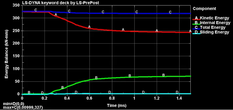
Starting with the energy balance of the simulation, we can observe that a big part of the kinetic energy of the bird is converted into internal energy through elastic/plastic deformations upon impact. Both energies do not cross in this case since the simulation time is small compared to the time needed to fully stop the bird. It can also be observed that the sliding energy slightly increases upon impact, yet, it remains neglectable during the simulation
The von misses stress distribution, along with the contact forces can be observed in the following video/figure
As expected, the maximum stresses develop in the elements that get deformed due to the bird impact, which, generates around 8 kN in force.
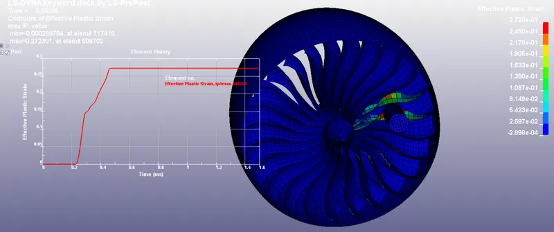
Plastic strain distribution over failed elements:
Conclusions:
- The maximum impact force generated by the bird is approximately 8kN, which is sufficient to induce large amounts of plastic deformation in the engine blades
- The simulation time was reduced almost by a factor of 3 by introducing a mass increase of 3.46% and mass scaling techniques
- From this simulation, FEA engineers can optimize the design by simply varying the blade material and/or thickness. Similarly, the effect of different element formulations, different coefficients of friction and even changing the approach to model the bird with SPH techniques can be studied