Week 8-3D Tetra Meshing Challenge
Week 8 Challenge - 3D Tetra Mesh
Objectives:
A. Learn the different Tetra Meshing Techniques
B. Learn the Quality Criterias for 3D Tetra Meshing
1. Mesh the given component under the next Quality Criteria:
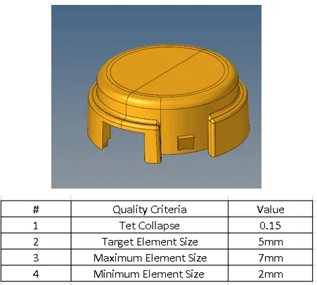
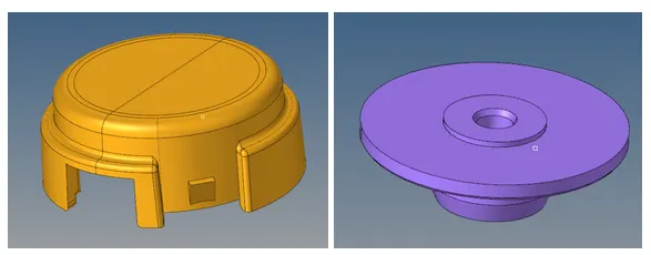
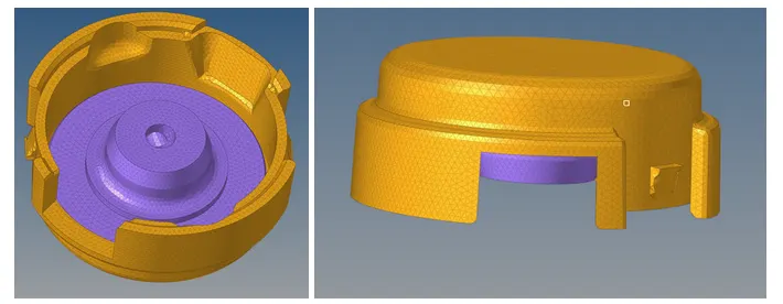
The housing geometry consist of two components, even though they are treated as one body by Hypermesh, we must organize the surfaces to be able to mesh both components properly
Starting by the outer geometry, the first step is to perform a geometry cleanup of all the fillets or edges that will cause elements to be smaller than the given minimum element size(2mm)
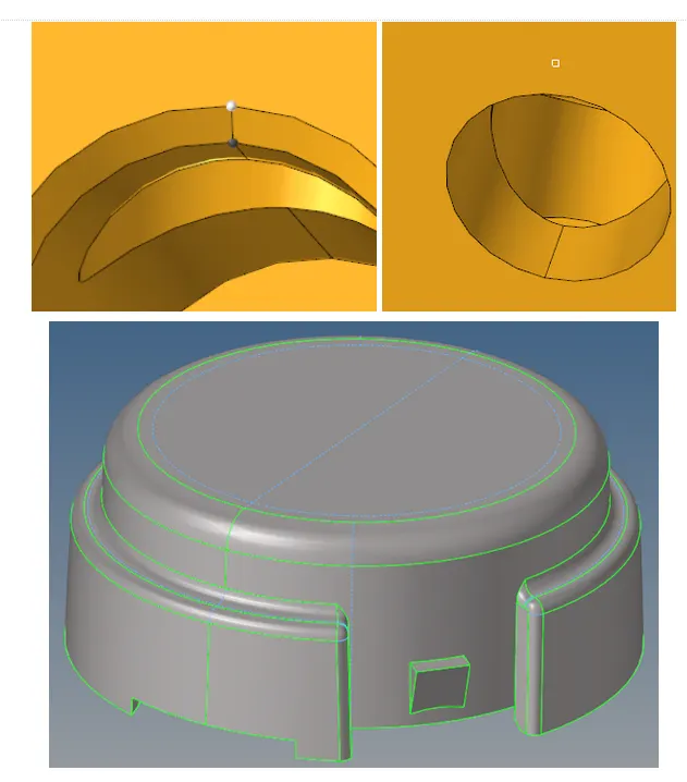
Once the geometry cleanup is done, we must start the 2D meshing of the critical areas such as the fillets and finally and corners, and then mesh the rest of the geometry with only tria elements.
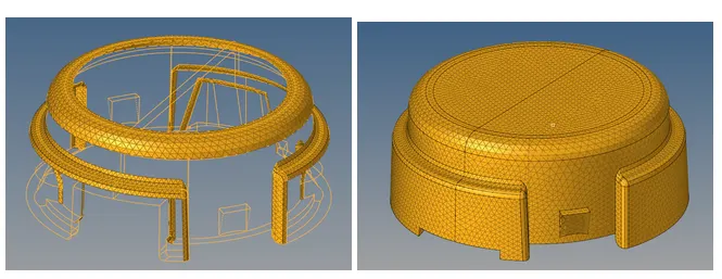
Once all the component is meshed, we must check for quality problems such as minimum/maximum element length and connectivity between the model
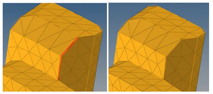
Finally, to convert the model into 3D solid elements, we must go to the tetramesh panel and select the option “Fixed Elements to tetra mesh”. It’s also important to delete the previous 2D shell mesh or we will have duplicate elements
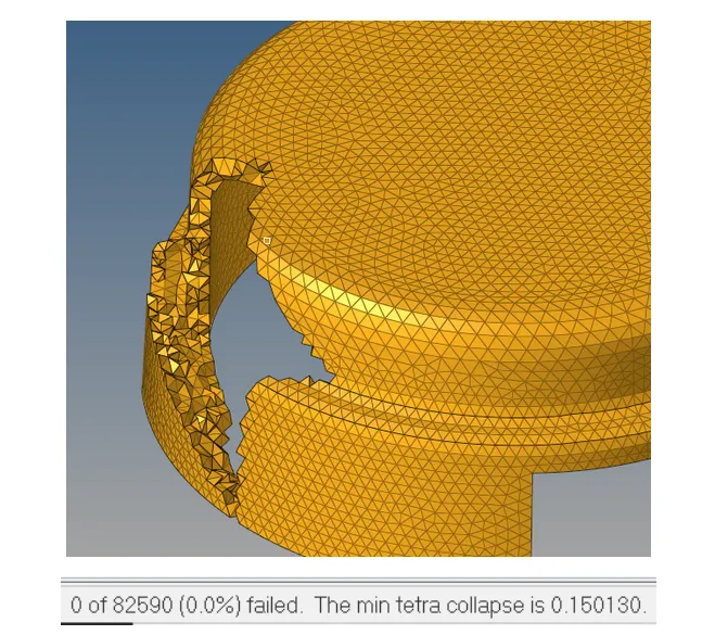
The last step is to check the tet collapse of the elements, but as we can see, in this case we don’t have any element collapsing. That’s why this is the preferred method to generate tetra mesh and the most used in industry. For the next models we will try other methods and compare their quality. We will repeat the same procedure for the inner body of the housing.
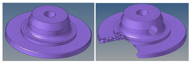
The final step is to also check the tet collapse of the elements, but in this case we also don’t have any for this method.
Final FEM model of the housing component:
2. For the given model, Create 3D tetramesh with 6mm element size.
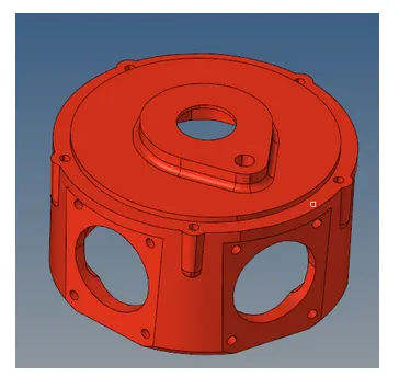
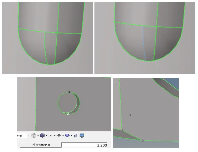
Starting for the Crank Housing model, the first step is to alse defeature the elements of the geometry that are below the desired element length. Due to the big element size specified(6mm), we will also patch the holes below this size
Once the geometry is ready we can proceed to work on the 3D tetra mesh, in this case we will try another technique for 3D tetra mesh, which is using the “Quick tetra” option in the utility panel. In this panel we can adjust some parameters such as mesh style and element length, but we don’t have much control on other important parameters such as tet collapse. We will choose a target element size of 6mm and a minimum of 3mm
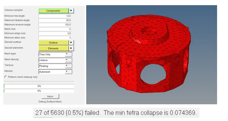
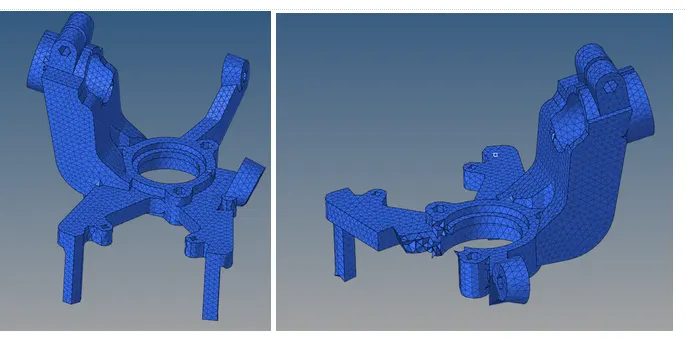
As we can see, not all the elements of the geometry were represented properly due to the big element size chosen for the model. Once the tetra mesh is generated, the last step is to repair all the collapsed elements. The procedure to repair these elements is to mask all and retrieve the failed ones, then unmask the adjacent elements and try remesh them with the “Tetra remesh” tool in the 3D panel (it’s important to adjust first the desired quality in the “Tetramesh parameters”).
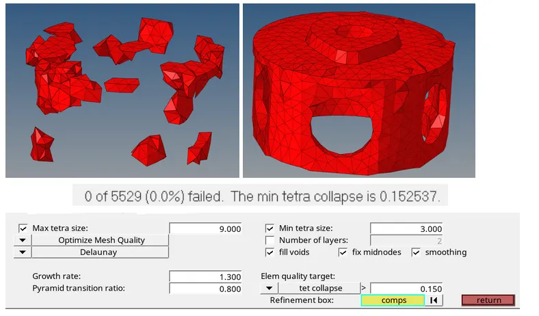
As we can see in the picture, this helped to solve all the tet collapse problems in the model. In case this doesn’t work we will have to move the nodes manually to repair the collapsed elements.
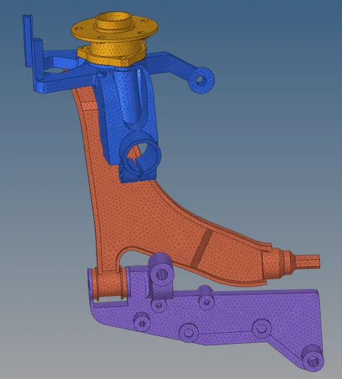
3. For the given assembly, Create 3D tetramesh with 6mm element size.
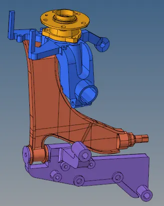
The previous assembly consists of 4 main bodies, which will be meshed in separate components. Starting by the upper body:
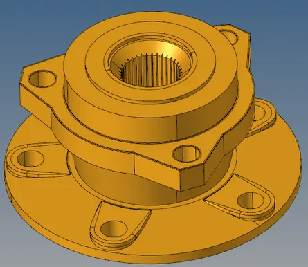
The first step will be defeature all the geometric parameters of the component that can’t be represented by the 6mm element size, such as the teeth in the center and the small fillets/borders all around the geometry
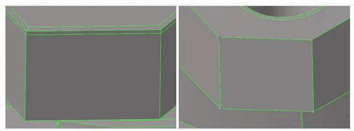
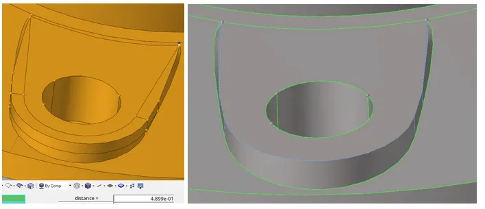
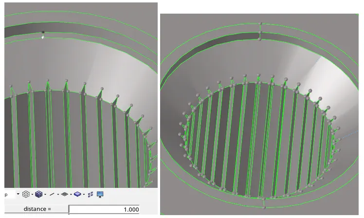
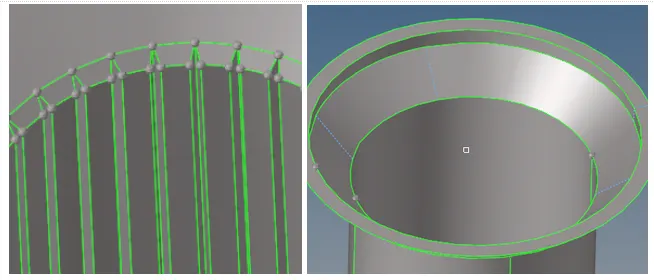
Once the geometry is ready, we will proceed to create a 2D mesh which will then be converted into 3D solid elements, again we don't have any tet collapses for this particular component
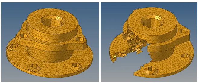
Moving to the second component
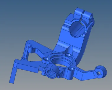
We will again start by defeaturing the elements of the geometry that can’t be captured by the 6mm element size
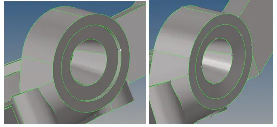
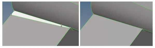
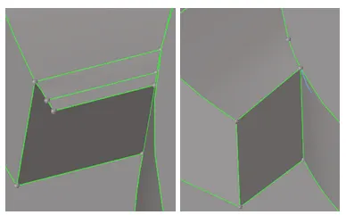
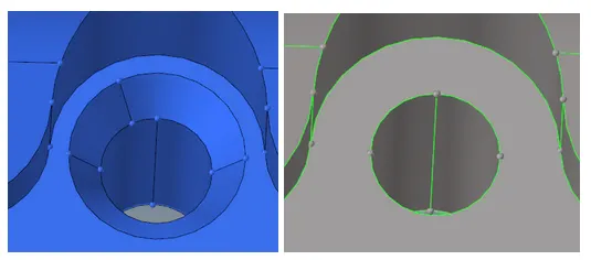
Once again we can convert the 2D mesh into 3D solid elements and finish by repairing all the collapsed elements.
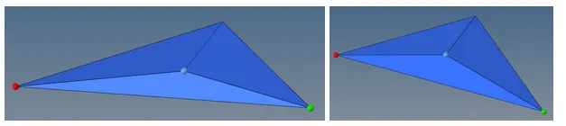
The procedure to repair the collapsed elements that fail by remeshing is to move manually the nodes with the translate tool, to do so we move the middle node away from its shortest side, hence increasing the height of the element.
The same procedure is applied to the third component of the assemblie
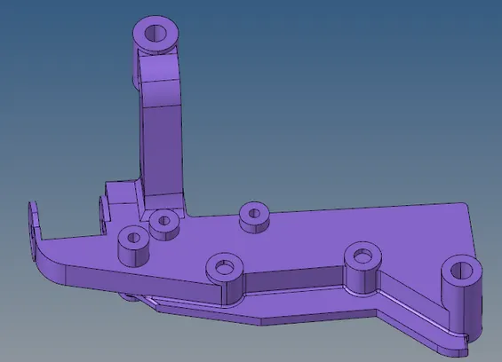
The main modifications this component needs are the defeaturing of the fillets all around the geometry, the mesh generation of this component will be done with the quick tetras option from the utility panel
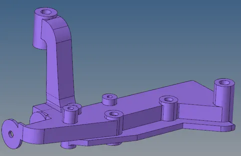
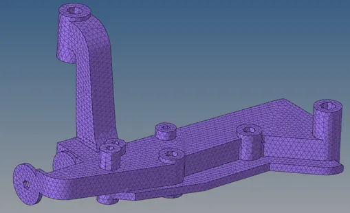

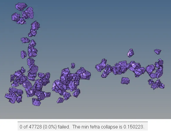
Yet we can see that for this particular component a lot of elements collapse, the procedure to repair them will be to use the remesh panel to try to reduce the number and finally move the nodes manually
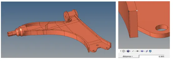
Moving to the last component, we can see that its maximum thickness is barely 6mm, hence we can’t simplify more the geometry. This component could be represented with just 2D elements. But given the instructions to mesh it as 3D solid elements, we will only clean the surface with the autocleanup panel and use the quick tetra panel to generate the mesh.
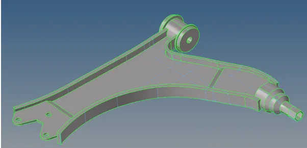
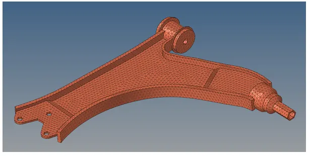
The final step to finish the model is to repair the collapsed elements in the same manner as the previous components
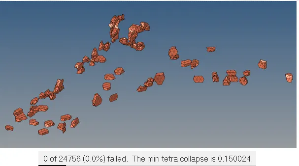
Final FEM Model: