Project 1-Meshing of Rear Wheel Holder challenge
Project 1-Meshing of Rear Wheel Holder
Objective: Mesh the given component under the following quality criteria
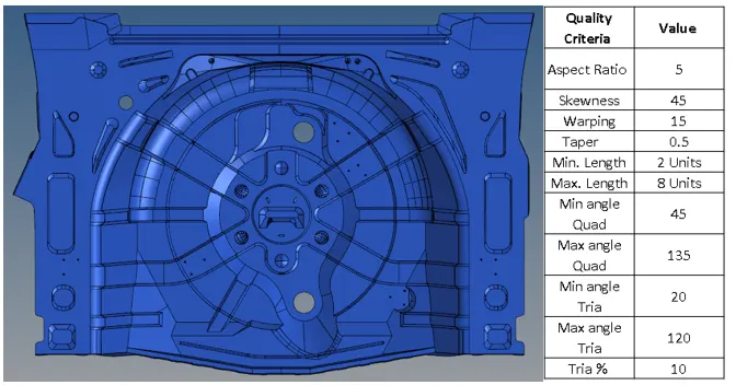
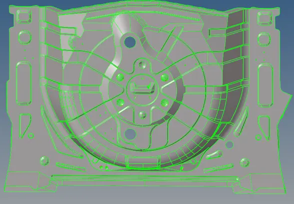
First, we must begin our 2D meshing process by deleting the solids and performing geometry cleanup/topology repair to increase our chances of obtaining an excellent mid surface
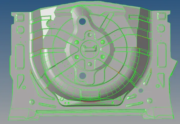
As we can see from the previous picture, multiple surfaces have bad connectivity or are entirely missing; thus, with the aid of the quick edit menu (F11), we will work on them individually.
Once all the surfaces have been fixed, we now have to get rid of the unwanted details that would otherwise ruin the mesh flow
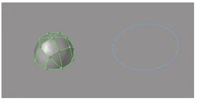
Once all these steps are done, we can proceed to extract the mid-surface of the component, which can either be done automatically in the auto mid-surface panel or by manually offsetting individual surfaces
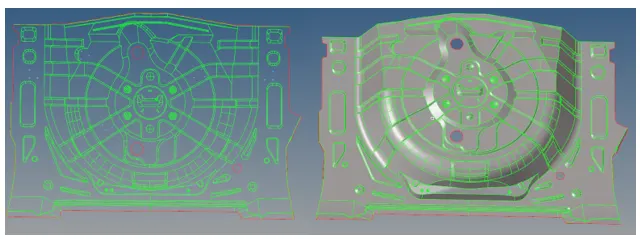
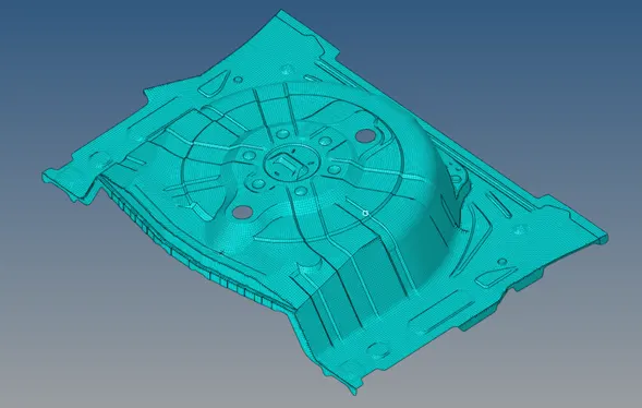
Once that is completed, we can start meshing the component. In this case, we will start from a general mesh and start local re-meshing on all the failed surfaces and regions which need a flow correction
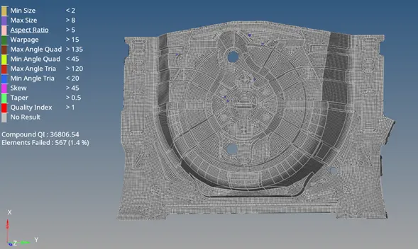
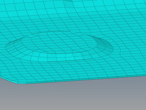
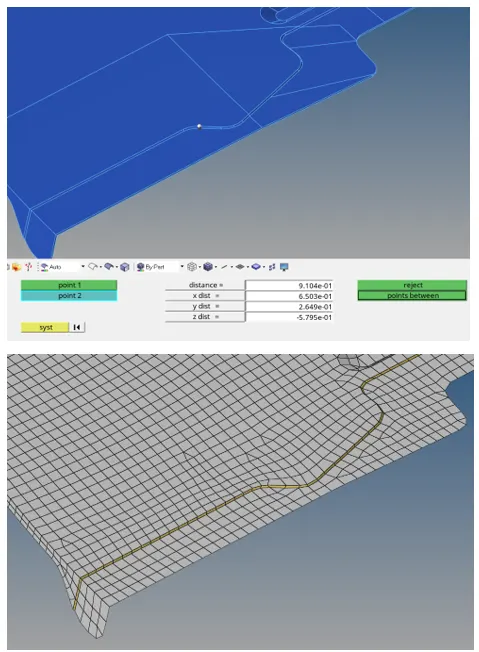
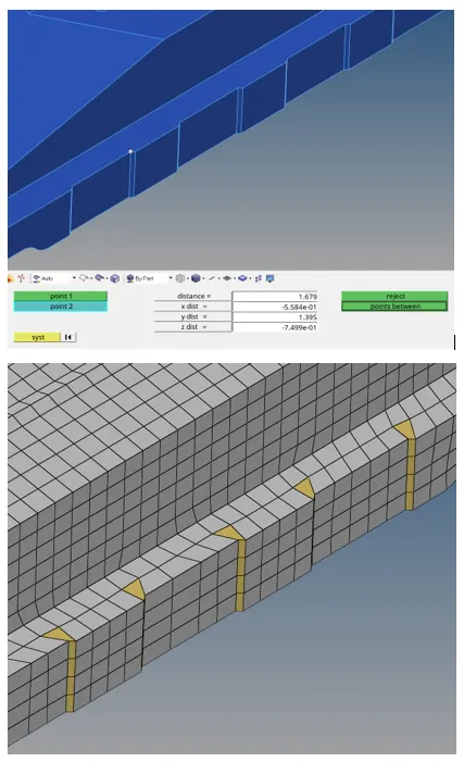
Due to the complexity of the geometry, some features cannot be appropriately captured without compromising element quality (especially minimum length criteria). For instance, this fillet runs through the entire component and has a length of 0.9 mm. Similarly, these facets on the entire outer part of the model have a maximum length of 1.6 mm
Once all the elements have the desired element quality, we can inspect for the element normals, which all have to point in the same direction.
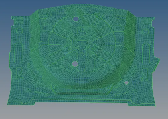
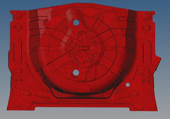
The next step is to check for Free edges, which is a must to ensure proper load distribution, and lastly, a geometrical comparison between our mesh and the extracted mid-surface.
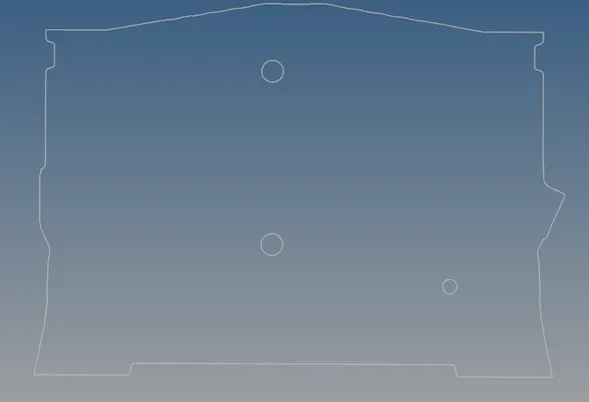
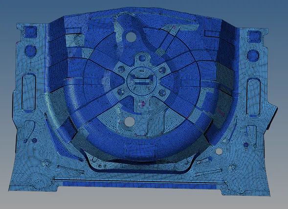
As we can see from the previous images, all the elements meet the specified quality criteria’s. All the normals point in the same direction. The only free edges correspond to the outer regions of the geometry, and all of the elements are in the matched/overlapped category with respect to the surface they are trying to represent.
The final step is to assign proper thickness to the elements. In particular, this is a sheet metal component with a constant thickness of 0.75mm. Thus, we must create a PSHELL property for all the 2D elements.