Week - 4 - Crash Box Simulation
Crash Box Simulation
Objective
Perform a crash box simulation and study the effects of part thickness in:
- Resultant forces/accelerations
- Directional stresses
- Maximum strain
Procedure
The first step is to import the model to LS-PrePost, which can be done using the "import Ls-Dyna keyword file" option
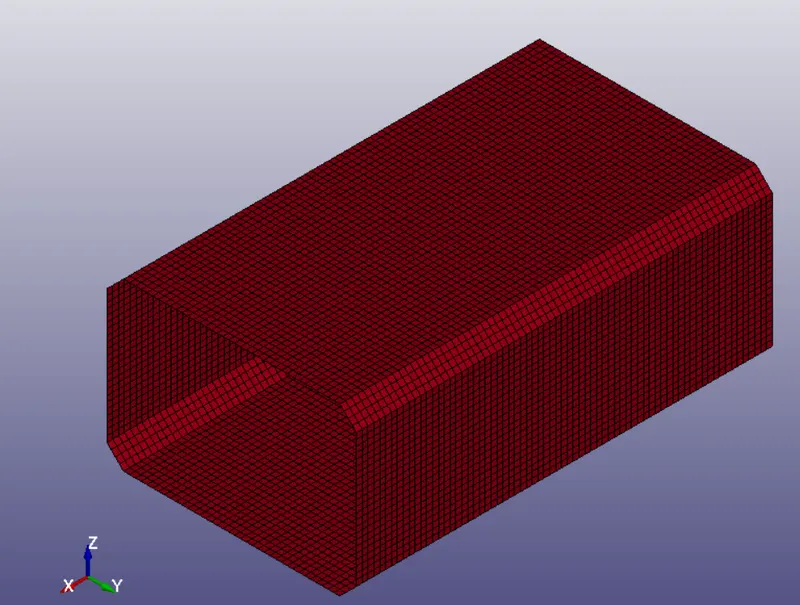
Once this is done, we can start to inspect the model with the aid of the Keyword Manager:
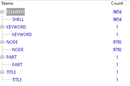
As observed, the model only contains the mesh for the simulation, therefore we can proceed by creating both material and section properties for all the shell elements.
Starting by the material, we will use the Keyword Manager to define an elastic-plastic material model (Material Type 24) to approximate the behavior of common structural steels
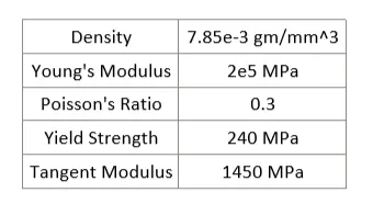
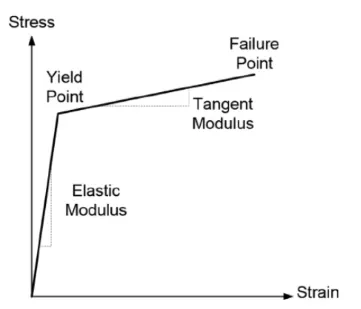
With regards to the section properties, we first must define a section ID which contains both the thickness of the elements, as well as the element formulation. For our first iteration, we will choose a 1.2mm thickness
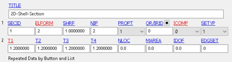
Once both of this steps are completed, we can go back to the Keyword manager and select the part that contains all the elements to assign both the Material ID as well as the Shell Section ID

The next step is to create the rigid wall that will collide against the part. To do so, we have to use the Create Entity Menu --> Rigidwall --> Create --> Flat (1n+NL)
Basically, this option allow us to specify the dimensions of a flat wall, and defines it with respect to a node and a normal direction. Once the rigid wall is created, we can use the translate command to place it centered with respect to the model
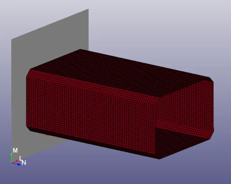
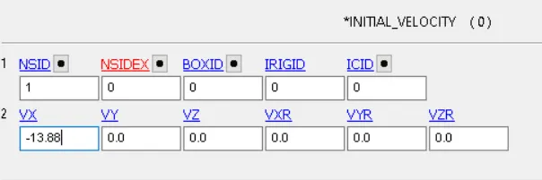
Once the model is completed, we can proceed to specify the boundary conditions for the model. The crash box will be given a 50 KMPH (13.88 mm/ms) initial velocity in the negative X direction
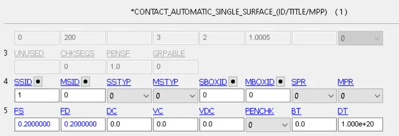
Since crash events are usually high strain events, we will define the possibility of the crash-box to become in contact with itself by specifying an automatic single surface contact. We will also assume a 0.2 dynamic and static friction coefficients
Once this is completed, we can define the control termination card to specify the duration of the simulation, as well as the Hourglass control definition (Ls-Dyna Default)
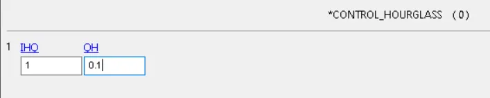
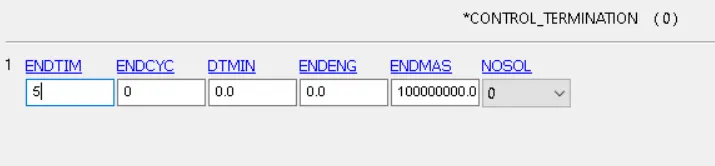
The last step is to define the output database Binary 3D plot and the ASCII files which contain all the information gathered during the simulation. We will choose to obtain the information of the simulation every 0.1 ms
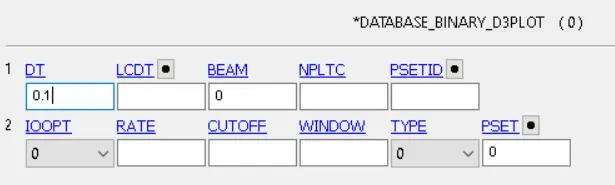
In terms of the ASCII options, we will go with:
- GLSTAT ---> Energy summary of the simulation
- MATSUM --> Specific material energy
- RCFORC ---> Resultant internal and contact forces
- NODOUT ---> Nodal point data
- RWFORC ---> Rigid wall forces
- SECFORC --> Cross section forces data
- SLEOUT --> Sliding energy output
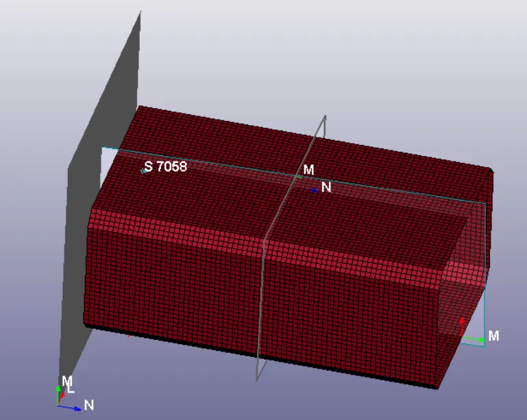
The last step is to create cross-sectional planes that we can use to post-process the results of the obtained stresses, forces and accelerations through out the simulation. To do so, we have to go to the Create Entity panel --> Database --> Cross Section --> Plane
Simulation Results
The first step into post-processing of any explicit simulation is to check the energy balance, from which, we will make sure that all the kinetic energy is converted into internal energy, and make sure that the hourglass energy remains neglectable.
The expected kinetic energy released from the impact can be calculated as:

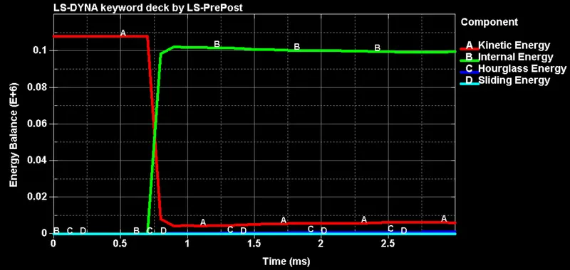
As expected, all the kinetic energy gets converted into internal energy, and the hourglass remains very at very low values. Is it also worth noting that the sliding energy is very low, meaning that the crash-box basically bounced back completely after impact, but didn't deform significantly
Stress/Effective Plastic Strain Distribution at the moment of Impact
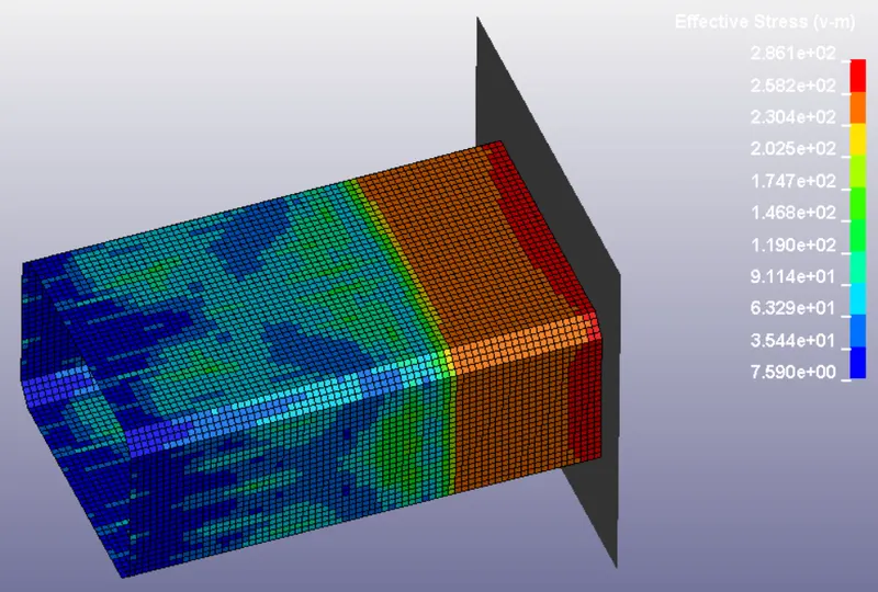
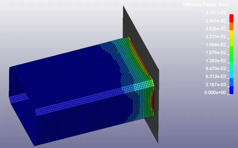
As observed in the previous figures, the effective stress developed at impact is slightly above the yield strength of the material, therefore, causing a slight plastic deformation at the top of the component. Later, the stress wave propagates through the rest of the part and produces only elastic deformation in the component as it bounces back from the wall
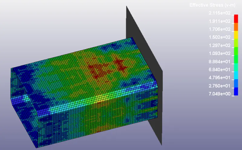
By loading the SECFORC ASCII file results we can obtain both the average forces and acceleration through the cross section of the crash box
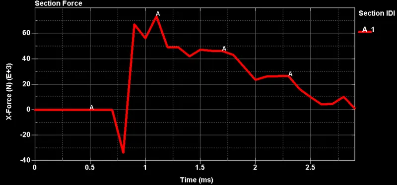
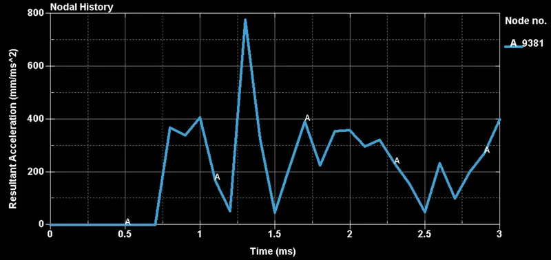
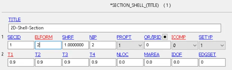
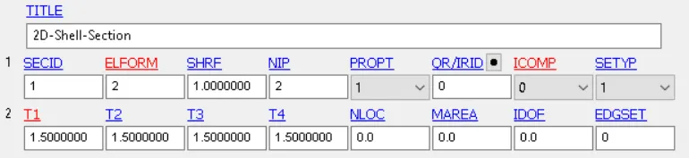
Lastly, we can observe the effects of varying the thickness of the crash-box by modifying the .k file. In particular, we will go with a thickness of 0.9 and 1.5 mm before comparing the resultant forces, accelerations, stresses and strain

As observed from the previous table, both the stress/effective strain levels slightly increase with the thickness, which can be ascribed to the added kinetic energy in the model. In terms of maximum forces and accelerations, as we increase the thickness the maximum forces increases, although the accelerations do not follow this pattern. This occurs because yielding of the material helps to dissipate energy.
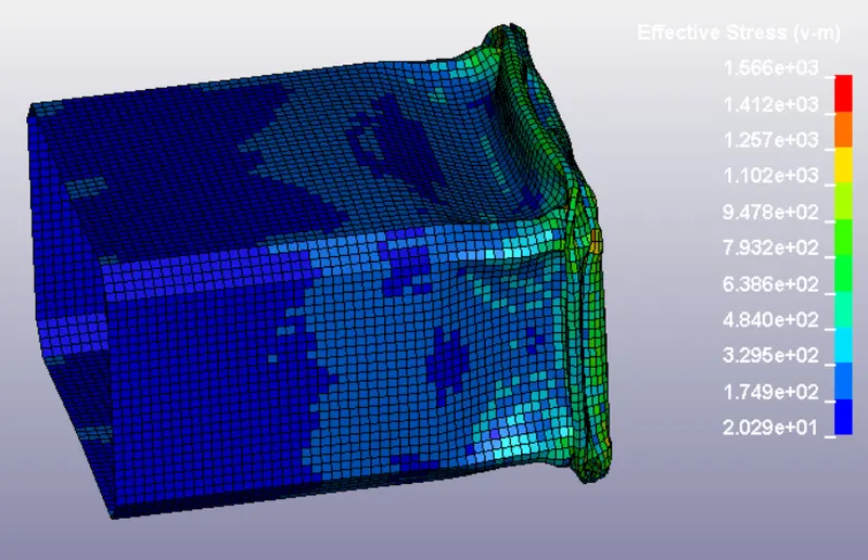
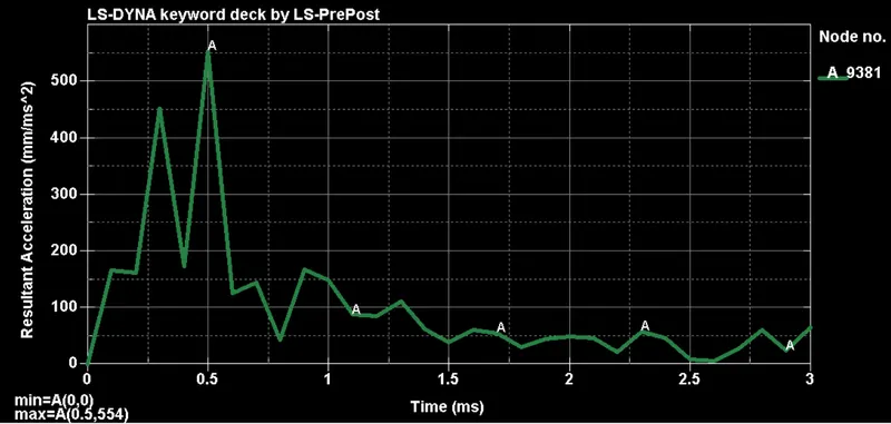
This effect can also be observed if we drastically increase the speed before impact so that we produce a lot of plastic deformation. For instance, if we increase the speed 10 times, the effective plastic strain becomes 1.617 mm/mm, but the maximum acceleration only reaches a 554 mm/ms^2, which is lower than in all of our previous cases
Link to effective plastic strain contour animations
https://drive.google.com/drive/folders/1O8W_Rcg_7Idz7tZKkRb-UMHlDCQEY0_O?usp=sharing
Conclusions
- Maximum stress and effective plastic strain are directly proportional to the thickness of the model
- As the crash-box yields, a lot of energy is absorbed from the model and therefore the resultant forces and accelerations reach lower values