Project-2-Meshing of Door Inner Panel Challenge
Project-2-Meshing of Door Inner Panel Challenge
Objective: Mesh the following geometry under the given quality criteria
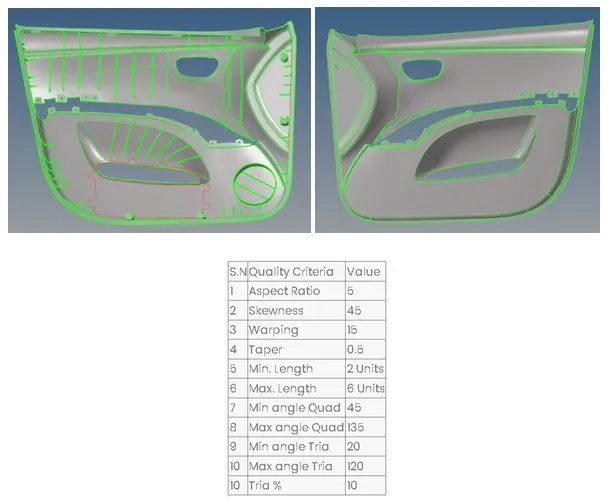
Any 2D meshing process starts by deleting the solids and performing a geometry cleanup of the component. In particular, there are many missing surfaces in the upper part of the model. Thus, to save time, we will only work on the lower part of the model and use it as a base for the mid-surface extraction. The second step is to remove small filets and defeature the ribs to increase our chances of properly capturing these features, which can be done automatically in the geometry tab.
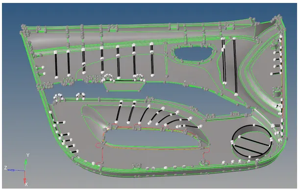
Given that this plastic component has variable thickness features, we will perform manual mid-surface extraction of all parts. To do so, we have to follow the next steps:
- Go to the offset panel
- Select the desired surfaces and click on duplicate
- Check the normal of the duplicated surfaces and adjust them properly
- Use the average thickness of the component as the offset distance
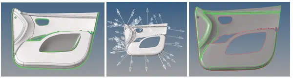
Once we have our parent surface, we can proceed to extract the rest of the features in the model, and use the surface edit tools to ensure proper connectivity.
For instance, some of the ribs in the model have a constant thickness; thus, we can use the surface pair command to obtain their mid-surface
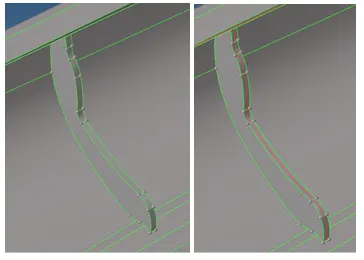
In contrast, other features have a non-constant thickness, thus to represent them correctly, we have to create a midline in the entire feature, and use that line to create the surface, which can be done in several ways, such as the ruled option in the surface panel
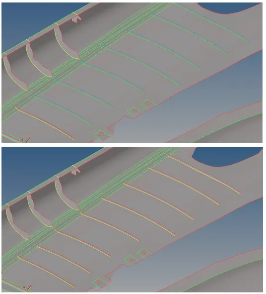
In particular, some features in the model have very complex geometry and low thickness and would interfere with the mesh flow. Thus, they will only be represented as flat elements
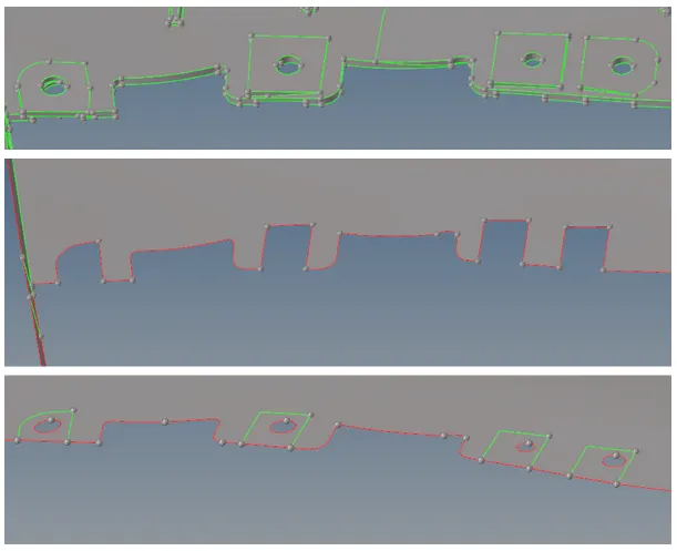
And some others have thicknesses way above 6mm; therefore, they can’t be represented with 2D elements and will be ignored.
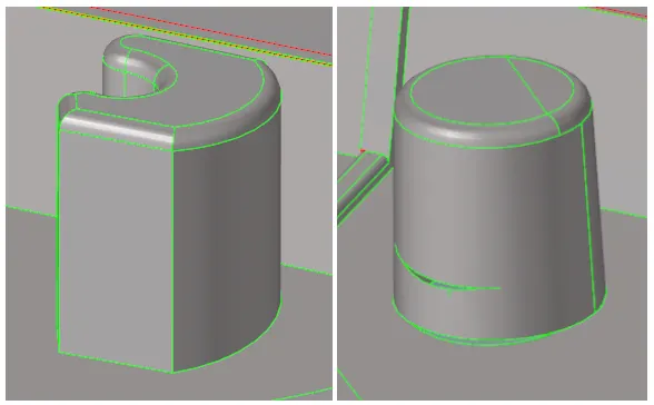
Resultant mid-surface:
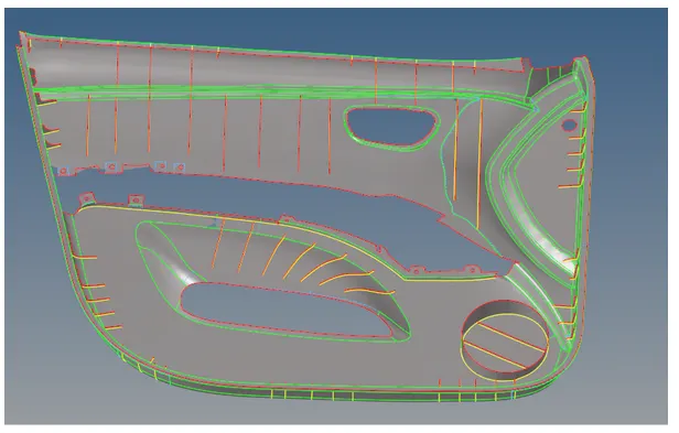
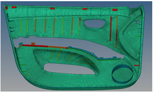
Once the mid-surface is completed, we can start the meshing process. In particular, we will start from the auto-generated 2D mesh and work in individual areas that need element cleanup or mesh flow adjustment until we get all elements following the quality criteria and the lowest amount of tria elements
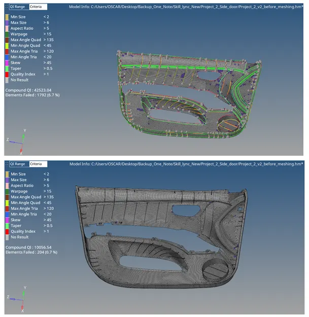
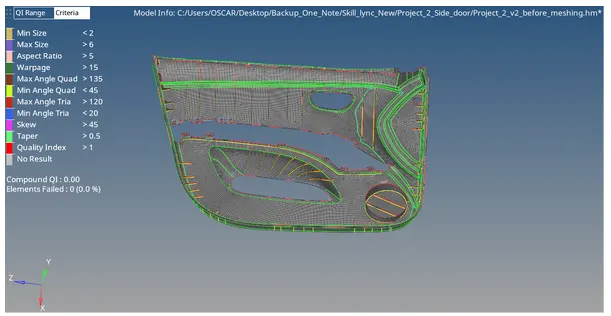
Once the mesh is completed, we have to check for free edges,duplicate elements and element normals, which have to point in the same direction to avoid unrealistic results.
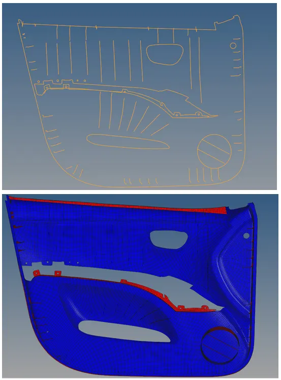
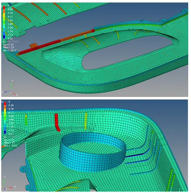
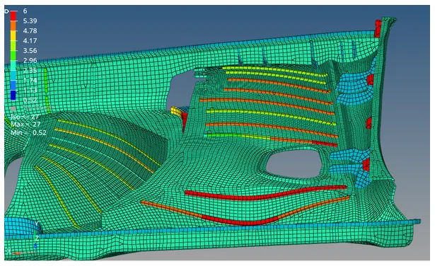
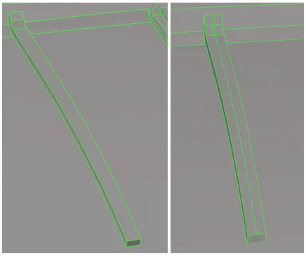
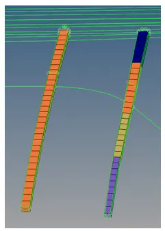
Lastly, we have to assign the thickness to the elements, which we can do by creating 2D PShell properties with fixed thicknesses. In the case of parts with variable thickness, we will use the mid-mesh thickness option to capture these components better, as shown in the following image, where we showcase a rib with the calculated average thickness and another obtained with the variable thickness option.
Final FE model: