Week 4- Challenge
Week 4 Challenge
Objectives:
- Familiarize with all the different 1D elements available in Hypermesh
- Learn the difference between Rod,Beam and Bar elements, and learn how to assign them different cross sections
A. Create 1D elements on the following component with given cross-section and DOF
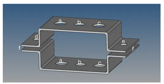
a. Rod element:- with only translational DOF and RBE2 link
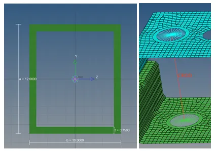
Cross-Section: BOX- Dimension a= 12 mm
dimension b=10 mm
Thickness t= 0.75 mm
b. Beam element:- with all DOF and RBE3 link
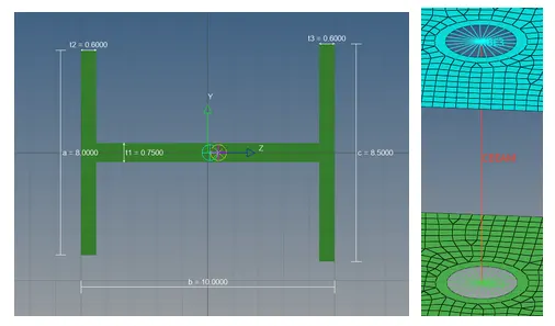
Cross-Section: I Section- Dimension a= 8 mm
Dimension b= 10 mm
Dimension c= 8.5 mm
Thickness t1= 0.75 mm
Thickness t2= .6 mm
Thickness t3= .6 mm
c. Bar element:- with only x and y DOFs With RBE3 link
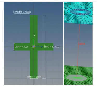
Cross-section: CROSS section- Dimension DIM1= 5 mm
Thickness DIM2= 1.2 mm
Dimension DIM3= 10 mm
Thickness DIM4= 1.2mm
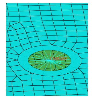
d & e. apply the mass of magnitude 10 with RBE2 link
f. Join the two components with Spring elements
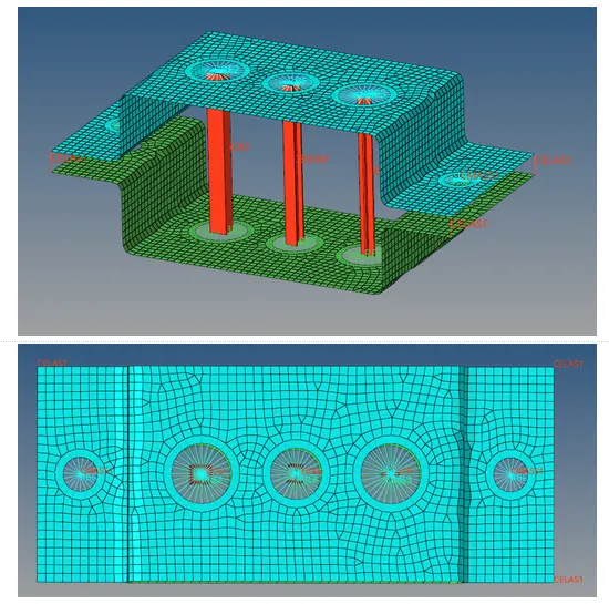
In order to create all the different 1D elements, a series of nodes are needed, so we proceed to extract a midsurface for this component and use the 2D mesh panel to create elements. To properly capture the holes with the 2D elements, we create one washer around each of the holes
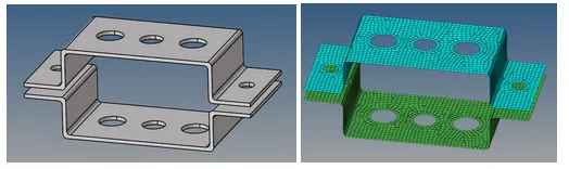
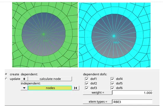
Rod Elements(a): As specified in the section above, the rod elements must connect and RBE2 link, have box cross section and only translational DOF’s, starting for the RBE2 link, this can be created using the “rigids” tool on the 1D panel, the independent node will be in the center of the hole and transmit all loads to the rest of the nodes on the hole(dependant nodes)
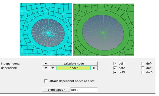
From the previous picture it’s worth noting that DOF’s 4,5 and 6 are not marked because they correspond to rotations in X,Y and Z, respectively. This process is repeated for the opposing hole on the second bracket
To create the box cross section, we need to go to the Hyperbeam menu from the 1D panel and under standard sections we must choose the thinwalled box option. then we must assign the length, width and thickness of the cross section. Finally, we must connect the RBE2 links with the rod element, to do so, we must create a property with the PROD card and the cross section we just created, and with the “rod” tool in the 1D panel to connect the independent nodes of the brackets
Beam Elements(b): The beam elements must have an I cross section and will connect RBE3 Links with all the DOF’s between the brackets. The process to do so is very similar to the rod elements, but we must use the RBE3 tool instead of the rigid one
To create the I cross section we must go to the Hyperbeam menu, and select standard I section from the “Standard section panel”, there we will specify the dimensions and thicknesses given in the previous section. The process to connect the RBE3 link with the beam element is very similar to the rod one, we must create a property with the CBEAM card and create the element with the “bar” tool on the 1D panel.
Bar Elements(c): The bar elements must contain a “cross” cross section and only the X and Y DOF’s connected with an RBE3 link. The process to create the RBE3 link is the same as the beam element but we must only select the 1,2,4 and 5 DOF’s that correspond to the X and Y translations and rotations, respectively.
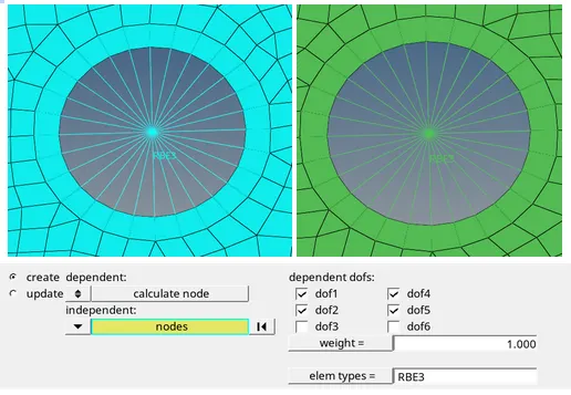
To create the “cross” cross section we must go to the Hyperbeam menu and under the Optistruct sections we must select cross and specify the dimensions from the previous section. In order to connect the bar element with the RBE3 we must repeat the process from the beam element, but we must use the the PBAR card
Mass element(d&e): Mass elements must connect RBE2 Links, the process to create them is the same as in the previous 1D elements, the only difference is that we will use the “masses” tool on the 1D panel to add the mas on the independant node of each hole(the card used was the CMASS).
Spring Elements(f): Spring elements are used to connect two components together with elastic properties, the only input corresponds to the nodes and the direction in which they act.In this case, the Y direction translation was activated and the corners of both brackets were joined with the spring elements
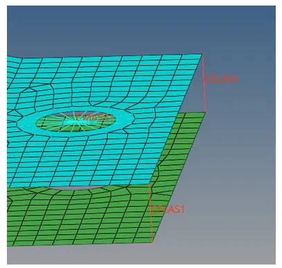
The final geometry with the detail representation of the 1D elements can be observed below: