Week-6 Calculate the Stretch Ratio by comparing the ELFORM (-2,-1,1,2) with Ogden_Material Model.
Objective
- Simulate a tensile test of a 10x10x10 mm cube component that behaves as a Hyper-elastic material
- Compare the results against the material model
- Use different element formulations (-2,-1,1,2) and compare results
Procedure
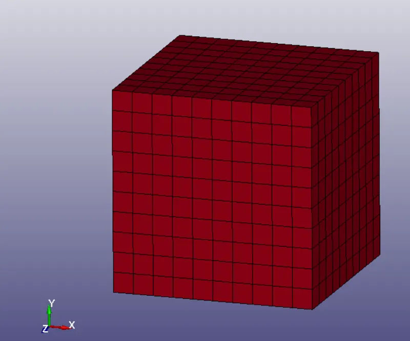
The first step is to model the test component, which can be easily done in Ls-Dyna using the Shape mesher option in the Element and mesh menu
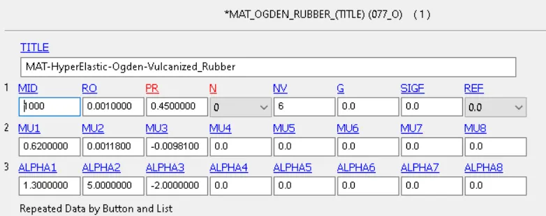
The next step is to assign the both the material card and the section solid keyword, from which we will be able to test different element formulations
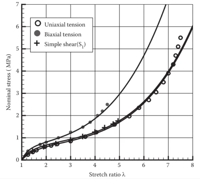
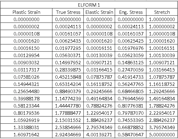
This material card was extracted so that it represents the following stress-strain distribution
Particularly, we will compare the simulation results by using the following element formulations:
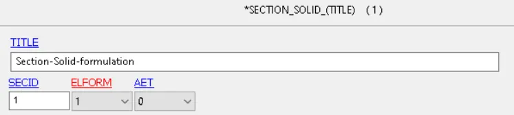
Case (1). ELFORM = 1, constant stress solid element.
Case (2). ELFORM = -1, Fully integrated S/R solid intended for elements with poor aspect ratio, efficient formulation.
Case (3). ELFORM = 2, Fully integrated S/R solid
Case (4). ELFORM = -2, Fully integrated S/R solid intended for elements with poor aspect ratio, accurate formulation.
In order to apply both of this properties to our elements, we must specify them in the part module
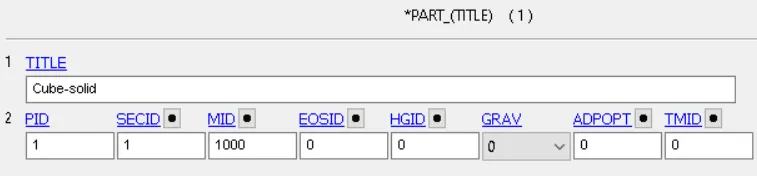
The next step is to apply boundary conditions. In order to simulate a tensile test we must:
- Block X translation of all elements in one of the faces
- Block all rotations about X,Y and Z
- Block Y translation from middle Z nodes
- Block Z translation from middle Y nodes
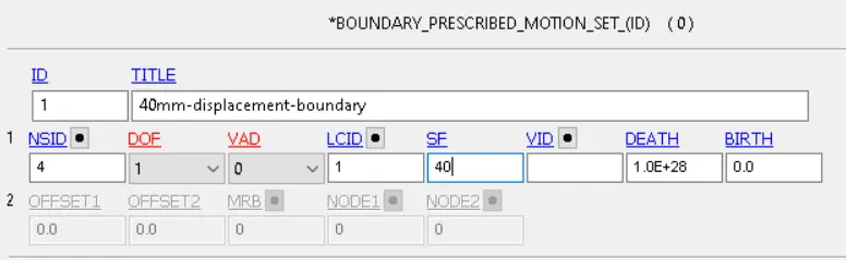
- Apply a 40 mm displacement in the positive X direction
To apply this conditions we must also create the node sets that support each group. This can be done using the create entity ---> Set Node option
In order to apply the displacement boundary condition we must define a curve that goes from 0 to 1 linearly, and then remains in 1 for a short amount of time to improve numerical stability
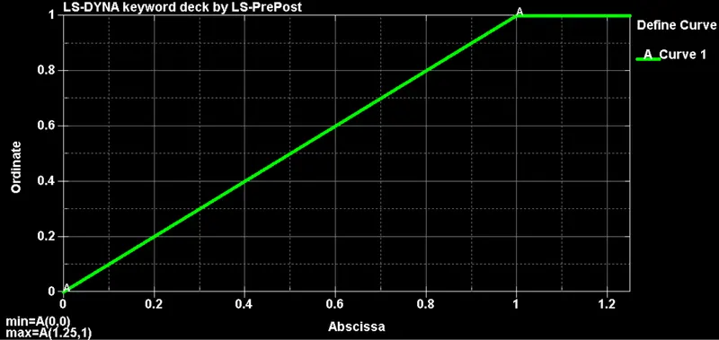
We will apply a 40.0 scale factor to this curve to represent the 40mm displacement boundary condition
The last step is to define our control termination cards and ask for our outputs in both D3PLOT and ASCII files
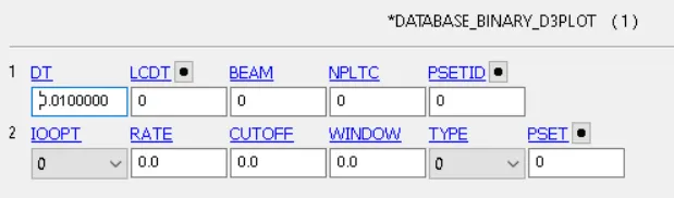
In terms of ASCII outputs, we will only go for:
- GLSTAT ---> Energy summary of the simulation
- ELOUT ---> Element Output data
Before we can use our ELOUT data, we must also define a Database History Solid keyword card. We will choose to follow a middle element inside the cube
Since the displacement is ramped in a quasi-static manner, it is reasonable to apply an implicit solution scheme for this simulation
To do so, we must activate the following Control Implicit keywords:
- Implicit General --> Activates Implicit Solver

- Implicit Auto --> Activates automatic time step adjustment

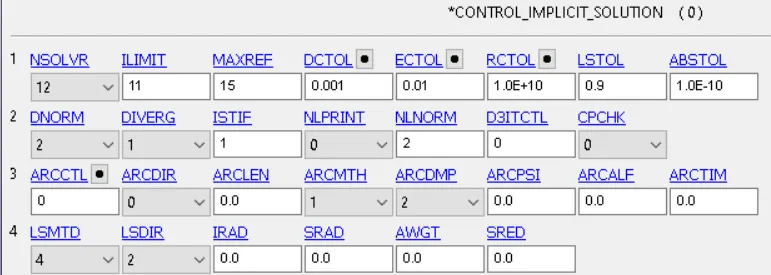
- Implicit Solution --> Non-linear solver configuration
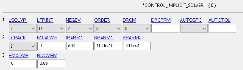
- Implicit Solver ---> Linear solver configuration
The last step is to run the simulation and use the ASCII output files to compute stress vs strain plots. We must consider that Ls-Dyna outputs true stress and strains, therefore we must convert them into engineering stress/strain by using the following equations:
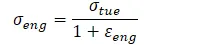

From there, the stretch ratio can be calculated as:

Simulation Results
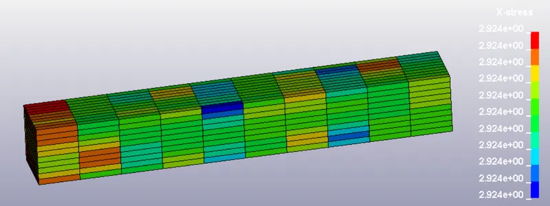
Stress Contour with ELFORM 1
Once we have the engineering stress/strain values, we can compare against our original material model, obtaining:
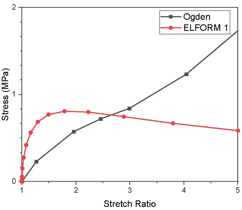
As observed in the previous figure, our specified material model doesn't match the Ogden model. This can be corrected by either changing the material definition (Ogden constants), or by modifying the boundary conditions
Ogden Hyper-elastic model:

By repeating the same procedure and defining the other element formulations we get:
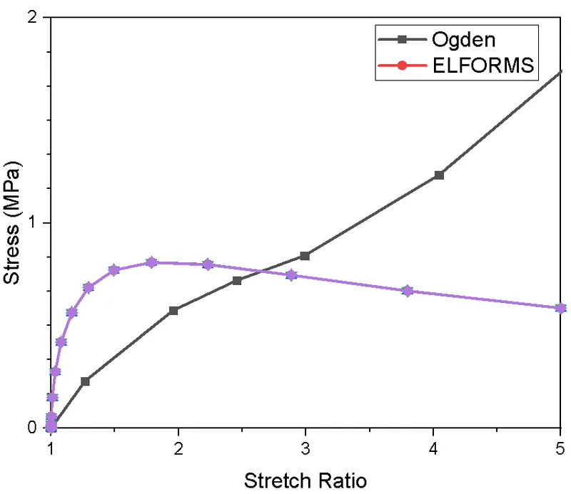
Due to the simplicity of the geometry and the problem, all element formulations derived on the same result. The processing time for all of them varied between 20 and 29 seconds, with fully integrated element formulation (-2) taking the longest to compute.
Conclusions
- The given material card doesn't match the numerical results, changes to the Ogden material constant are suggested
- Fully integrated elements provide better accuracy at the cost of computational recourses
- Given the simplicity of the model, all solid element formulations output the same stress/strain values