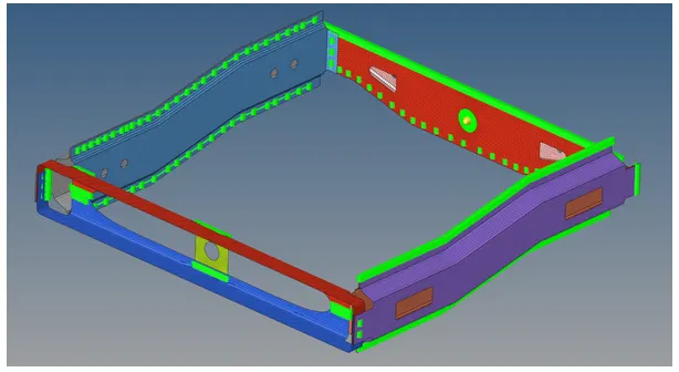
Week 9-Creation of 1D Connectors Challenge
Week 9 Challenge - 1D Connectors
Objectives:
A. Learn the different 1D connector options
B. Mesh the given assembly with proper connectivity and Mesh Quality
- Mesh the given geometries under the next Quality criteria:
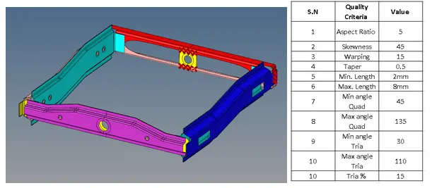
Since we already have the midsurface of the components, we will simply proceed to use the automesh panel to do a quick mesh on all components. Later on we will worry for the quality criterias since the connectors modify the mesh when realizing
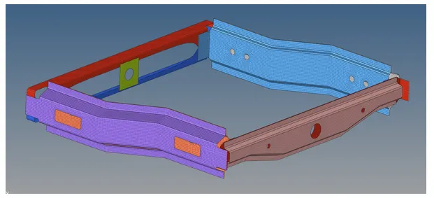
Once we have meshed all the components, we can proceed to create the 1 connectors ,and remesh the failed elements
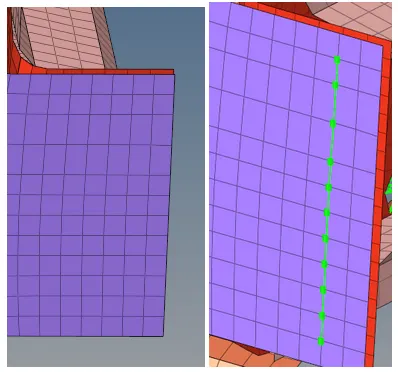
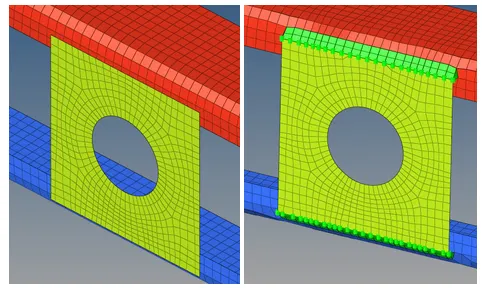
Right_Rail_2 & Front_truss_1:- Seam-Quad(angled+capped+L)
To create this type of connector we must go to the 1D panel > connectors > seam, and finally establish a tolerance and weld angles. The tolerance is assigned based on the distance between components(3mm), the spacing is based on the mesh element size(5mm) and the weld/cap angle will be left by default(60° and 75°)
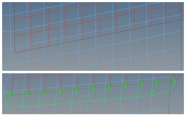
Now that the seam weld is created, we must proceed to remesh the areas to pass the quality criterias
Left_Rail_2 & Front_truss_1:- Quad elements
The procedure to create quads as connectors is similar to the seam weld one, but in this case we will only have to specify the tolerance(3mm) and the spacing(5mm)
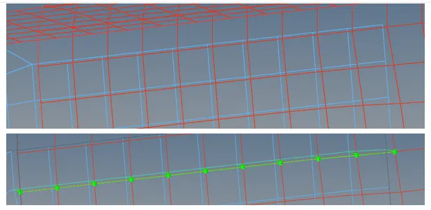
Once again we must do element cleanup for the established element criteria
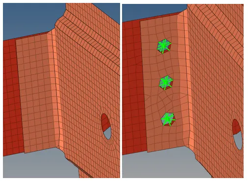
Front_truss_2, Front_truss_1 & Right_Rail_1:- Spot weld with 3 Layers and 5 mm Diameter
A spot weld can be used to merge two or more components(this will be the number of layers), other important parameters are the diameter of the weld, and the tolerance which is based on the distance between components
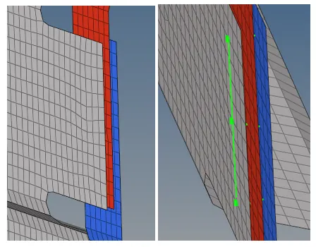
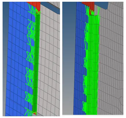
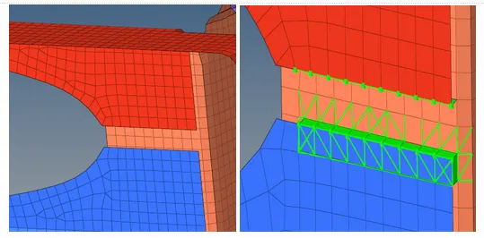
Front_truss_2, Front_truss_1 & Left_Rail_1:- Hexa (Adhesive)
The Hexa adhesive option is also a seam connection, and it’s very similar to the quad connection but with solid elements. The important parameters are again the spacing, tolerancing and strips/coats which means how many Hexa elements we want
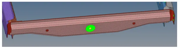
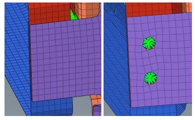
Rear_truss_2 & Right_Rail_2:- Bolt Connector
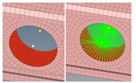
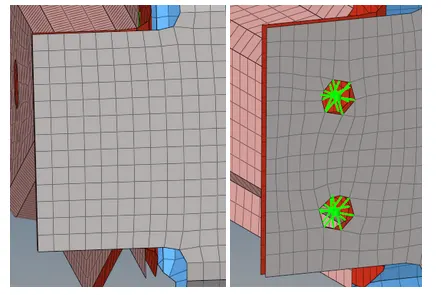
A bolted joint is the most common type of connection in machine design, bolts are represented with RBE2 elements due to their stiffness. The important parameters to create this type of connection is mainly the gap between components and the diameter of the bolt
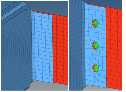
The problem with this type of connection is that it will disturb the mesh significantly, hence we must check for the quality afterwards.
Rear_truss_2 & Left_Rail_2:- Bolt Connector
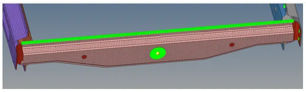
Right_Rail_1 & Right_Rail_2:- Spot-weld with Rigid Elements
Even though we use another type of connector, the parameters for the spot weld remain the same, we must specify the spacing and the tolerance for the RBE2 elements, which will be used to join the entire upper part
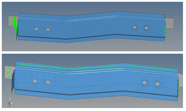
Left_Rail_1 & Left_Rail_2:- Spot-weld with Spring Elements
The same applies to the spring elements, but they will connect the lower part of the model
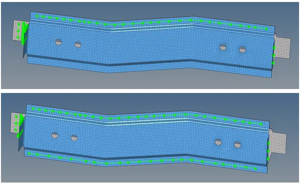
For the rest of the model we will create bolts in the small brackets and holes, rigid elements on the upper part and welds/springs on the lower sides, we will also include some adhesive if the contact area between components is large
Final FEM model: