Week-7 Head Impact
Pedestrian Head Impact Simulation
Objective
Perform a pedestrian head impact simulation in the following three cases:
- Simple head model impacting a rigid wall
- Detailed head model impacting a rigid wall
- Detailed head model impacting an aluminum car bonnet
At each case, maximum stresses, accelerations and Head Injury Coefficient (HIC) must be obtained and compared.
Background
CAE Pedestrian protection is a branch of vehicle crashworthiness which intends to prevent/diminish the risk of injury on "Vulnerable Road Users", such as pedestrians, cyclists and electric wheelers users.
According to the World Health Organization, road traffic accidents result in approximately 1.3 million deaths every year, with vulnerable road users accounting for nearly 54% of these fatalities. Among the various factors contributing to pedestrian fatalities, head injuries have been identified as one of the most predominant.
Therefore, various head injury criteria's have been stablished over the last decades to asses the likeliness of survival based on maximum head accelerations/duration of impact, some examples include:
- Head Injury Criterion (HIC)
- Brain Injury Criteria (BRIC)
- Cumulative Strain Damage Measure (CSDM)
- Head Impact Power (HIP)
These models aid CAE engineers to design energy-absorbing features/structures/designs to enhance pedestrian safety
A common test used to evaluate pedestrian protection is the EURO NCAP Pedestrian Protection Tests. These tests employ individual dummy prototypes to assess the crashworthiness of different areas of the car that are likely to come into contact with a pedestrian.
For instance, a dummy of the lower leg is used to evaluate the protection offered by the bumper, while a dummy of the upper leg is used to assess the protection provided by the leading edge of the bonnet. These tests help determine the effectiveness of energy-absorbing features, structures, and designs in minimizing the risk of head injuries and other forms of harm to pedestrians.
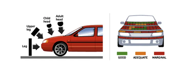
Therefore, CAE engineers play a critical role in pedestrian protection, working to prevent or minimize the risk of injury to vulnerable road users. By employing head injury criteria, conducting tests, and optimizing vehicle designs, they contribute to the continuous improvement of vehicle safety and the preservation of human life on our roads.
Case I)
Simple Head Model Impacting a Rigid Wall
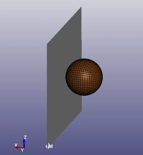
To perform this simulation, the following steps must be completed:
Define the thickness of the shell elements using a Section Shell Keyword
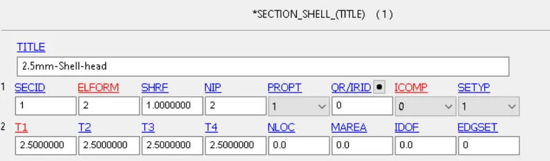
Create a material property that represents the skull mechanical behavior, which for this iteration of the project, will be defined using a linear material model

Assign both the material and section to the shell elements in the part module
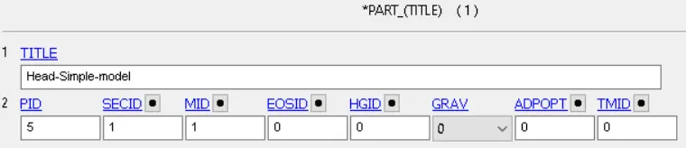
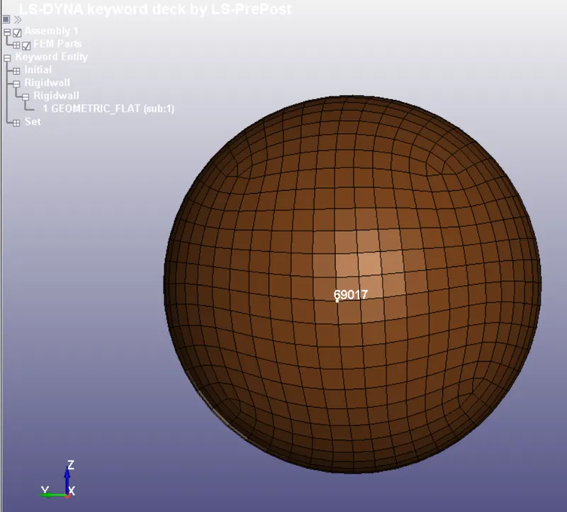
Create a node set of all the shell elements to input a 35 Km/h initial boundary condition in the positive x direction
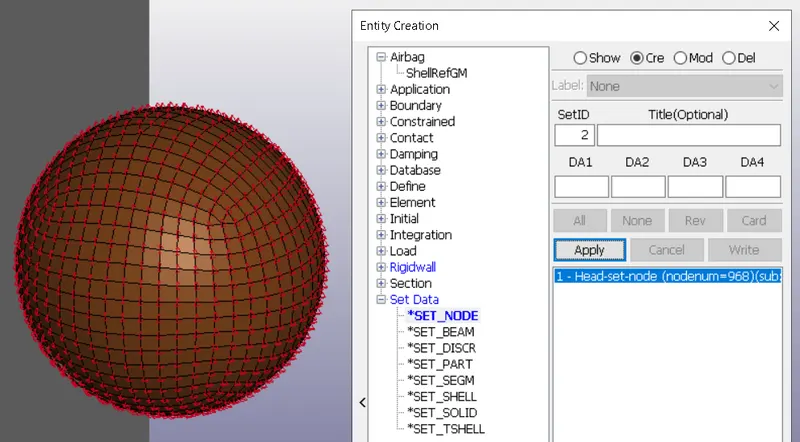
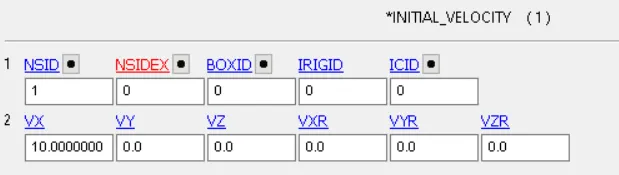
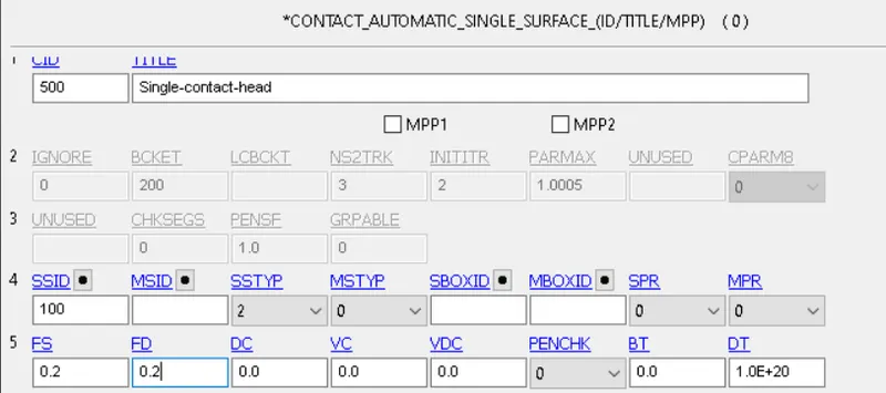
We must specify a Single Contact Surface to avoid penetration between the shell elements nodes. To do so, either a set segment/part must be created
The last step is to define our control termination cards and ask for our outputs in both D3PLOT and ASCII files
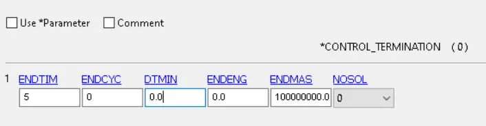
In terms of our outputs we will go with:
In terms of ASCII outputs, we will only go for:
- GLSTAT ---> Energy summary of the simulation
- MATSUM --> Specific material energy
- RWFORC ---> Rigid wall forces
- SLEOUT --> Sliding energy output
- NODOUT ---> Node Output data
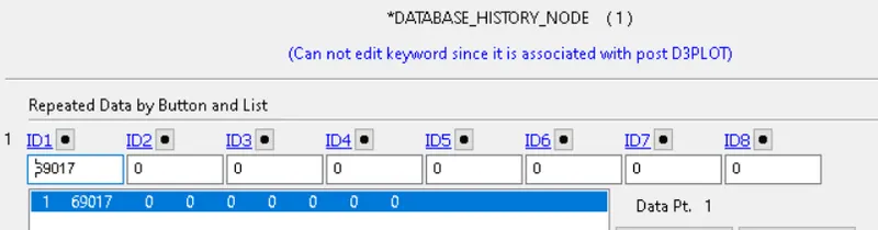
We also have to define the nodes which we want to analyze by means of a Database-History-Node Keyword. In this particular case, we will analyze the accelerations of the center node in the simplified head model
Simulation Results
The first step in the post-processing of any simulation is to check for the final energy balance. The expected total energy for this simulation should be equal to the kinetic energy of the head model before impact, which can be calculated as:

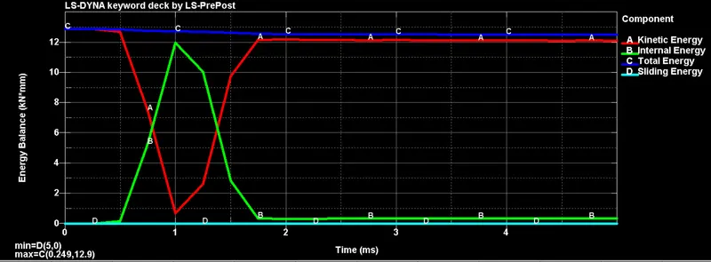
As expected, all the kinetic energy gets converted into internal energy at the moment of impact. Since we used both a linear material and a rigid wall, the head bounces at the same initial velocity from the wall.
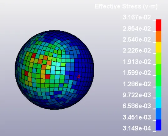
The obtained stress distribution can be observed in the following animation, from which, a maximum stress of 31.67 MPa is obtained
Lastly, by using the information saved with the NODOUT Ascii file we can calculate the HIC value for this case
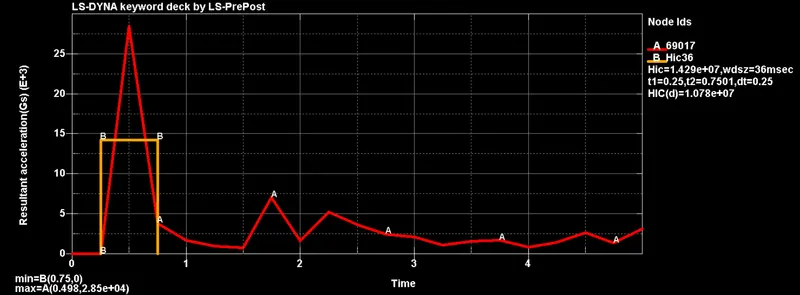
This HIC value can be calculated analytically as:



The difference in the HIC value obtained by Ls-Dyna is because the software can integrate the acceleration at all points, while for the analytical calculation we only used the average in the impact points (14,159). Either way, this HIC exceeds the 1860 maximum value stablished by the Euro NCAP regulations
Case II)
Detailed head model impacting a rigid wall
The new head model adds complexity to the previous case by changing the shape of the head as well as including several elements such as the skull, skin and a backplate with an accelerometer at the center of mass of the component. Each component has its own material definition as either a rigid material (MAT 20) or an Ogden material model (MAT 77)
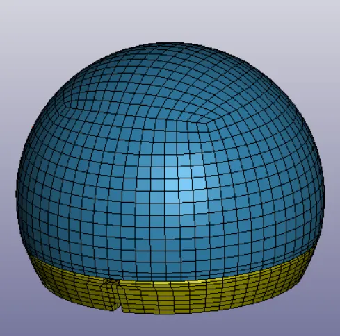
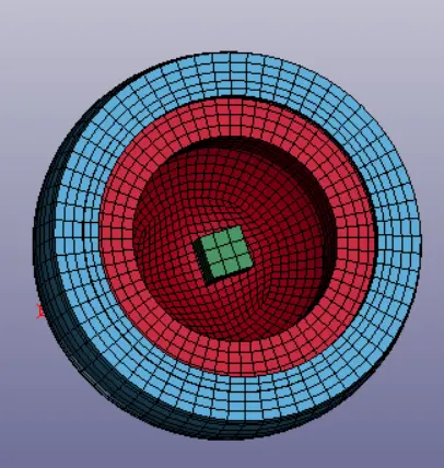
In addition, this case will also follow the EC78/2009 Pedestrian head impact test, in which, the head will impact the rigid component at a 50° angle at a 35 Km/h speed
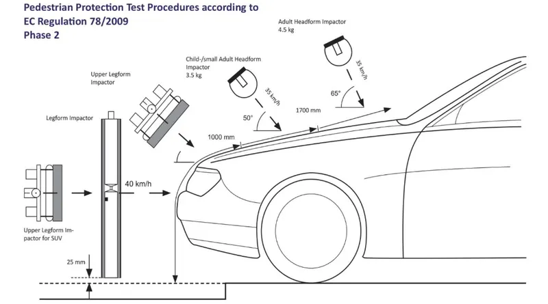
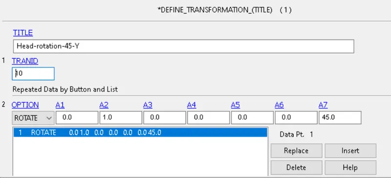
Thus, the first step is to apply a transformation keyword to rotate the model 50°.
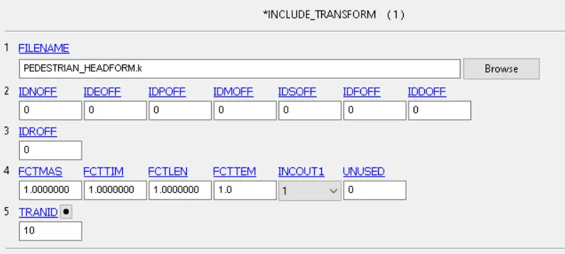
Lastly, the Include Transform Keyword must be used to indicate in which file we will apply the transformation
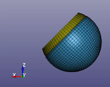
After saving the file and re-starting Ls-PrePost we get the model at the desired position
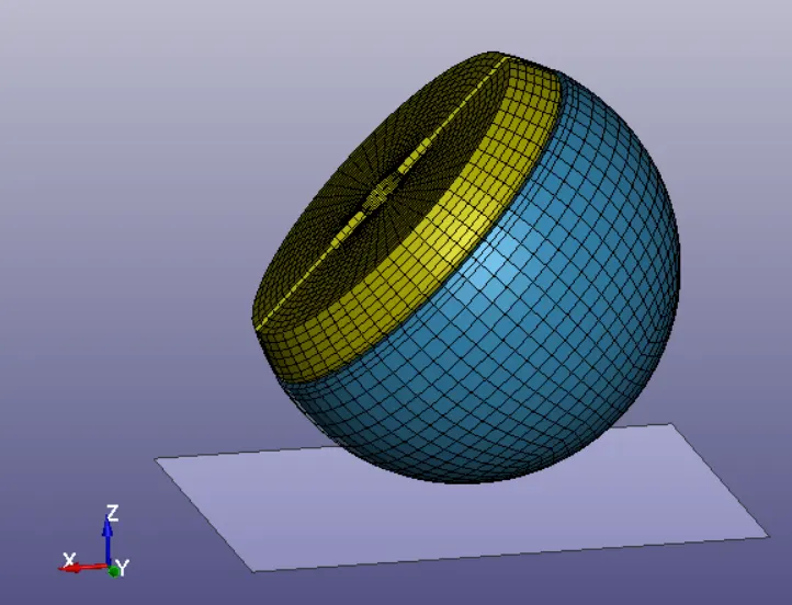
The next steps before running the simulation include creating the rigid wall and applying the 35 Km/h velocity
In order to apply the initial velocity, a node set containing all the model must be created such as in the previous case
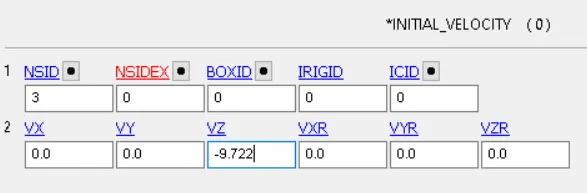
Lastly, the control termination card and the ASCII output options must be defined. We will use the same configuration as in the previous case

In this case, we will also use a extent binary keyword with since we expect to obtain plastic strain due to the material definition in the model
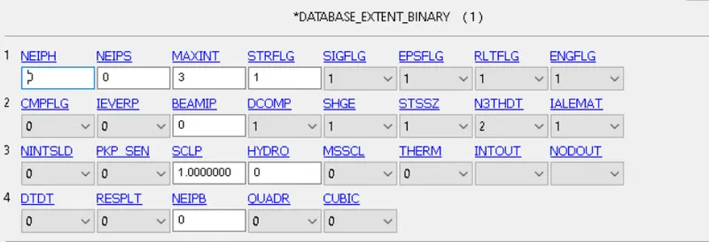
ASCII output files:
- GLSTAT ---> Energy summary of the simulation
- MATSUM --> Specific material energy
- RWFORC ---> Rigid wall forces
- SLEOUT --> Sliding energy output
- NODOUT ---> Node Output data
Simulation Results
Once again, we start by analyzing the energy balance through the simulation. The expected total energy should be equal to the kinetic energy, which is calculated as:

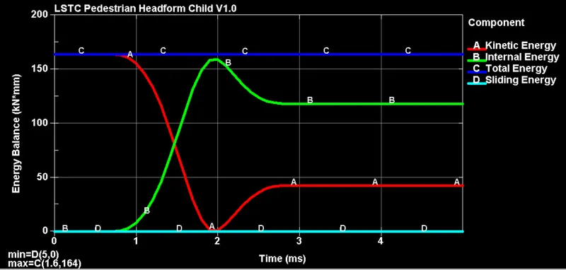
Although the behavior of the curve is similar to the first case, we can see that since the material definition allows for plastic deformation not all the kinetic/internal energies are completely reversed after impact.
Both the effective stress and plastic strain can be observed in the following pictures:
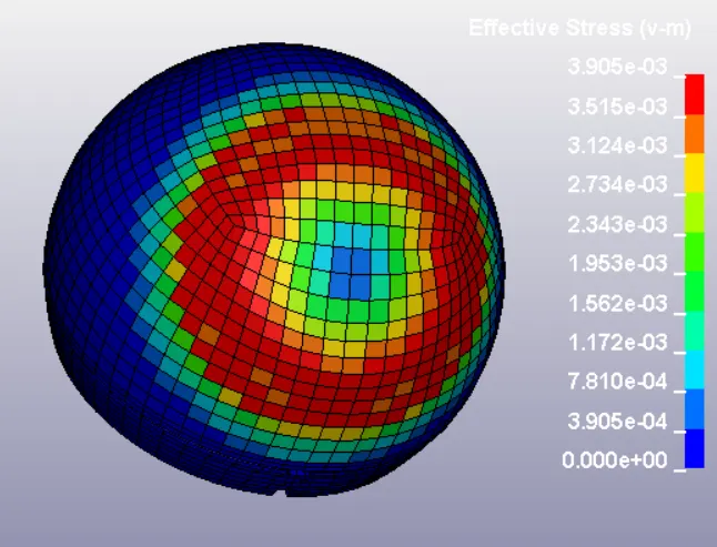
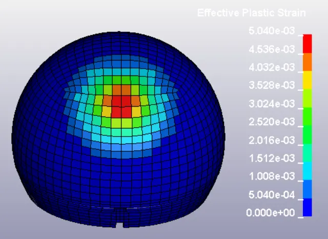
Animation of the simulation:
Lastly, the HIC values must be obtained using the information gathered in the accelerometer component.
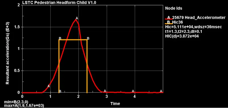


In this case, since the skin material allows for plastic deformation the maximum acceleration is more than 10 times smaller than the previous simulation due to the energy dissipation through yielding. Thus, the HIC value is considerably lower
Unfortunately, this HIC value still indicates zero probabilities of surviving the impact.
Case III)
Detailed head model impacting an aluminum car hood
This case adds complexity to the simulation by substituting the rigid wall with a 2mm thick aluminum hood.
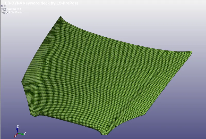
The first step into performing this simulation is to import the pedestrian head model using an Include keyword. Since we already have a file with the model rotated 50° degrees, we don't have to do the transformation again
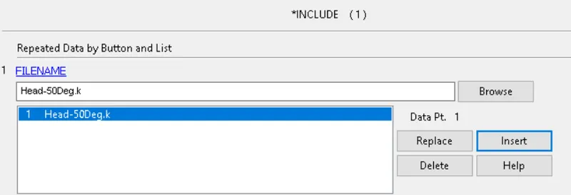
After saving and re-staring Ls PrePost we get the entire model
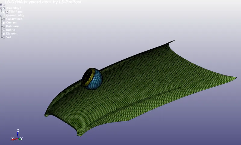
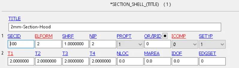
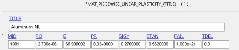
The next step is to define both the section and material properties of the hood, which can be done with a Section-shell and MAT 24 keywords
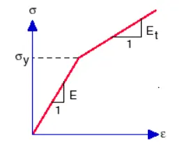
Mat 24 (Linear plasticity) proposes a linear stress distribution after the yield stress with a slope equal to the tangent modulus, as shown in the following figure.
The required material properties to define this model are:
|
Density |
2700 Kg/m^3 |
|
Young's Modulus |
68.9 GPa |
|
Poisson's ratio |
0.334 |
|
Yield Stress |
276 MPa |
|
Tangent modulus |
562 MPa |
The next step is to define the boundary conditions for the simulation, which include:
- A 35 km/h speed at the 50° angle
- Fixed edge nodes on the hood model
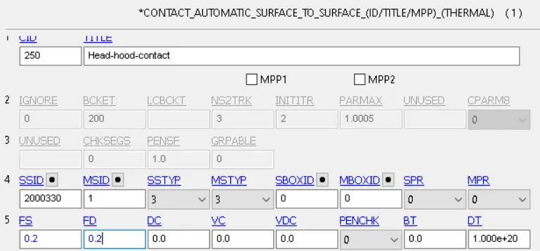
- Contact between the head model and the hood
The speed has to be decomposed using the 50° angle, obtaining:


In order to specify the fixed nodes in the hood model, a node set containing only the nodes on the edge has to be created. By using the By path option we can easily select all these nodes before creating the Boundary keyword.
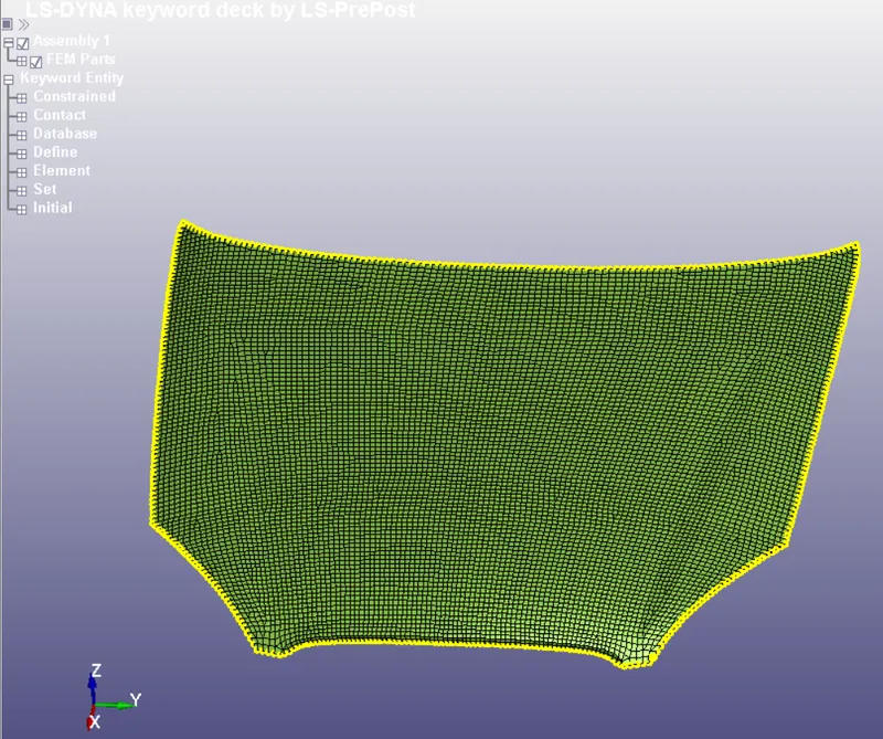
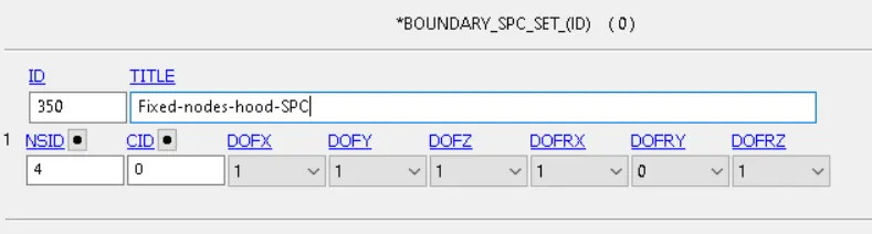
The contact between the head and the hood has to be performed using an Automatic surface to surface contact. We will define the hood as the master and the head as the slave
The last step is to create our control termination card and specify our ASCII outputs. We will use the same configuration as in the previous two cases, with the difference that we will swap the rigid wall forces for SPC forces
Simulation Results
The total kinetic energy remains the same as in the previous simulation since both the velocity magnitude and the mass of the head are the same.
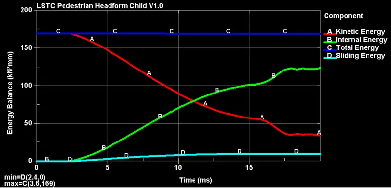
From the energy plot several thing can be observed.
- After impact, all the kinetic energy of the head gets converted into internal energy
- After the impact, most energy is used in yielding of the hood and the head
- Some fraction of the kinetic energy is converted into sliding energy, meaning that the head moves in some direction after impact rather than fully bouncing back
All these points get confirmed after looking at the stress/strain distribution of the simulation, in which a maximum of 282 MPa is reached at the corners of the hood, which undergo some slight plastic deformation
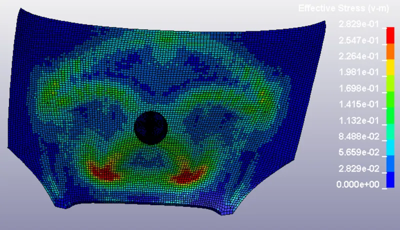
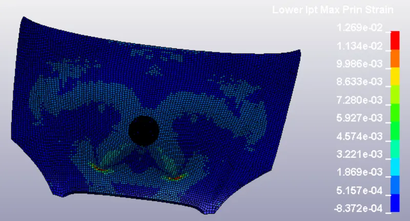
Due to the material definition and the boundary conditions, most of the deformation occur elastically in the hood. A more realistic scenario would include other components bellow the car bonnet which effectively increase the rigidity of the hood, which would cause the head to suffer larger stresses/strains
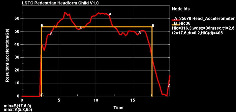


With this HIC there is high chances of headaches and dizziness, but low probability of linear/depressed/open fractures. This occurs because most of the energy is used into elastically deform the hood and therefore reducing the acceleration values upon impact.
Conclusions
- From cases I and II we can observe that acceleration values greatly increase if the impacted object is modeled as rigid, since all the kinetic energy will be gained back by the head in the form of rapid accelerations
- From case III we can observe that the relative stiffness between the head and the bonnet determines the magnitude of the obtained HIC. Therefore, hood geometry and material properties play a very important role in pedestrian head protection measures
- We could keep adding complexity to the model by including other elements that go below the hood, or by taking into account the added stiffness that they provide