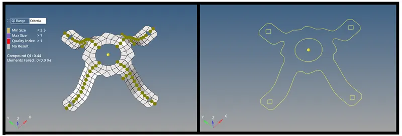
Assignment 1-2D Meshing Challenge
Week 1-2D Meshing Challenge
Objective
Carry out a geometry cleanup and 2D meshing of the following sheet metal components:
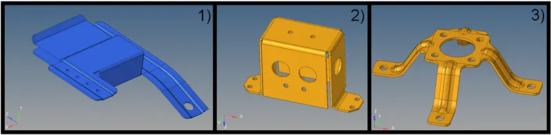
- The 2D mesh should have a target length 5mm, minimum of 3.5mm and maximum of 7mm
- There should not be any free edges in the final mesh
- Ignore all the holes with a diameter less than 5mm
Procedure
Starting by part 1, the first step is to change the visualization to "By 2D Topo", which will show us the conflict areas within the surfaces of the model
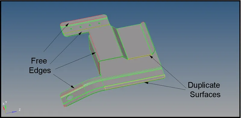
As observed in the previous figure, there a multiple connectivity problems along with some duplicate surfaces along the model. All these issues can get solved by using the Quick edit (F11 shortcut) and a combination of the following commands:
- Toggle edge
- Delete surf
- Insert/Replace points
- Filler surf
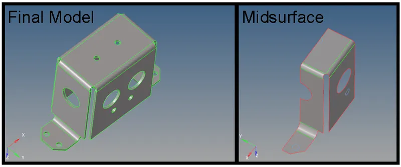
Once the model is fully prepared, we can proceed to extract the midsurface. Since this is a sheet-metal component, it has a constant thickness so we can do this process with the auto-midsurface extraction default options
Some of the features, like pin-holes and fillets have less than 3.5 mm in size, therefore they cannot be represented without causing quality issues in the mesh. Therefore, we use toggle and filler surf commands to defeature them before proceeding to the 2D meshing process
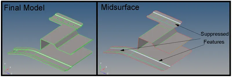
Since the geometry is very simple, the 2D meshing process is carried out in one operation with the auto-mesh menu (F12 shortcut). Opposite sides in the model get the same number of nodes so that we get almost a full quad mesh, which later gets refined manually with the "Quality Index" menu
Once all elements pass all the quality criteria's, we can proceed to check for free edges in the model using the Shift + F3 shortcut. The tolerance value will be equal to our minimum element size so that we don't miss any free nodes
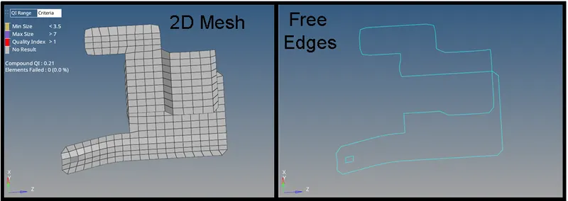
As expected, since the entire mesh was done in one operation there are no connectivity issues in the mesh and the only free edges correspond to the borders of the model.
Part 2
The second part doesn't have any topology errors, so we can proceed directly to obtain the midsurface. Yet, as observed from the figure, this model is symmetrical in both X and Y axis, so the procedure will be to only mesh a quarter of the model and reflect the elements.
Once again, we will also suppress the pin-holes that have less than 5mm in diameter in order to improve mesh flow. We will also try to reduce the number of tria elements used while keeping our quality criteria's in check
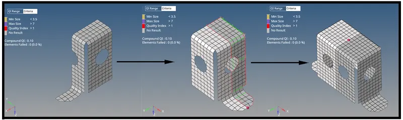
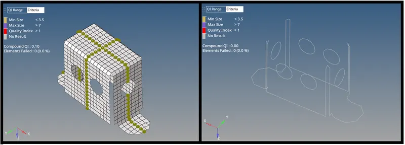
The last step is to equivalence the nodes at the reflected interface and check for any other free edges in the model
Part 3
Similarly to the previous part, the next component is already suitable to extract the midsurface, and it also posses symmetry along Y and X axis. Yet, multiple features in this model are much smaller than the 3.5 minimum element length stablished. Therefore, we must suppress those features before starting the 2D meshing process.
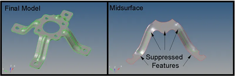
Once the midsurface is ready, we can proceed to use the auto-mesh panel. Once again, we will try to avoid using tria elements while keeping the maximum/minimum size of the quads within the specified criteria
Once the mesh is done, we will rotate it 90° around the Z-axis to produce half of the model, which later will be reflected in the Y-axis to produce the full model
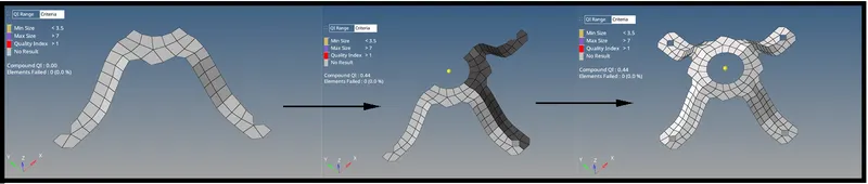
The last step is to equivalence the nodes at the reflected interfaces and check for any other free edges in the model