Week - 5 - Modelling Spotwelds
Challenge 5 - Modeling Spot Welds
Objective:
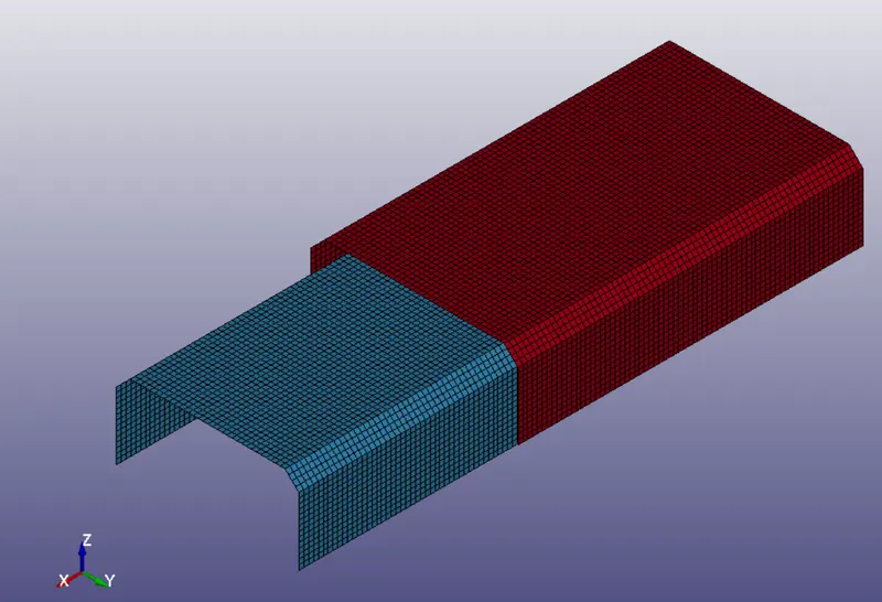
- Perform an Impact simulation of two sheet metal components joined by Spot Welds:
- Model the spot welds as beam elements
- Model the spot welds as solid Hexa elements
Procedure
Case I)
Spot weld generation using CBEAM Elements
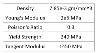
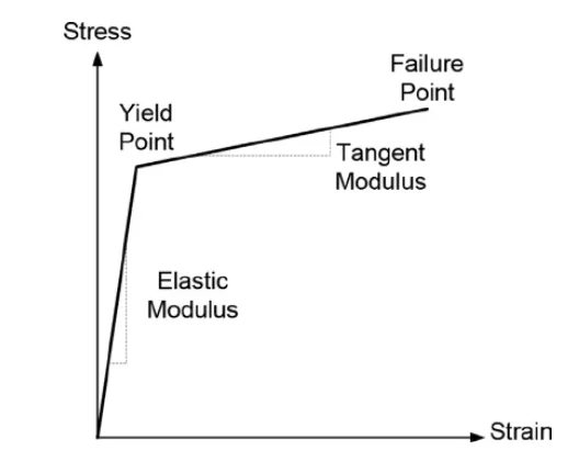
The first step after exporting the model as a .k file is to create both the material card for the sheet metal and the spot welds. To do so, we must go to the Keyword Manager and select an elastic-plastic material model (Mat 024) for the sheet metal components
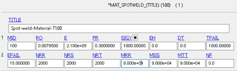
With regards to the spot weld material, we will also use steel material properties along with the keyword *MAT_SPOTWELD (Mat 100)
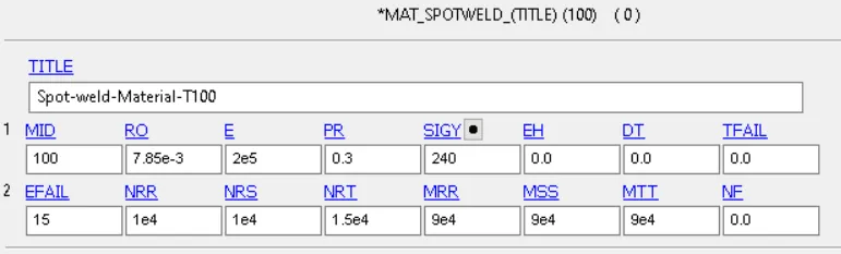
The values for EFAIL, NRR, NRS, NRT, MRR, MSS and MTT represent either forces/moments in which failure is supposed to occur on the weld. This will be guess values, since they must be obtained under physical testing. Later on the simulation we will adjust this values so that the welds fail during the simulation
In order to apply this material to the sheet metal components, a section card which contains the details of the element formulation and thickness must be created. This can be done using the *SECTION_SHELL keyword
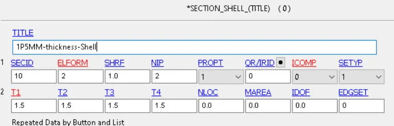
In order to define the spot welds in the model, we must go to the mesh menu and select create beam element. From here, we simply must select the pair of nodes that we want to be our spot welds
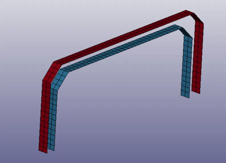
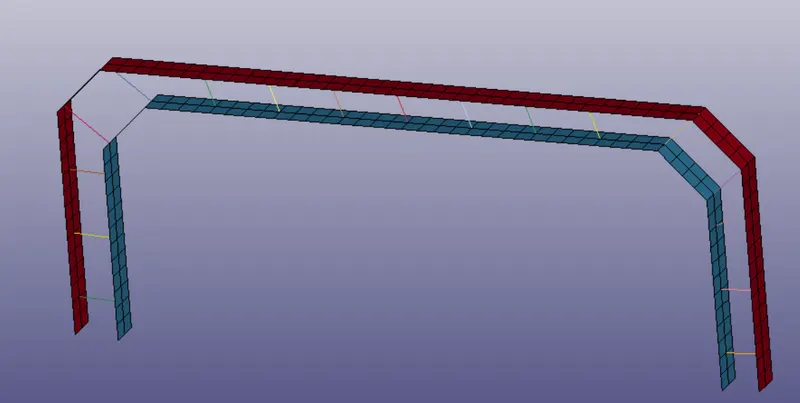
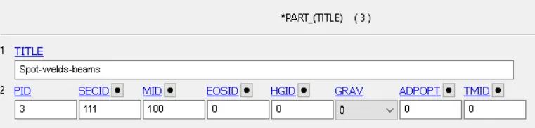
Then, we can simply select the part module and assign both the material and the section ID of the beam elements
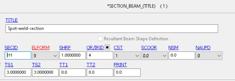
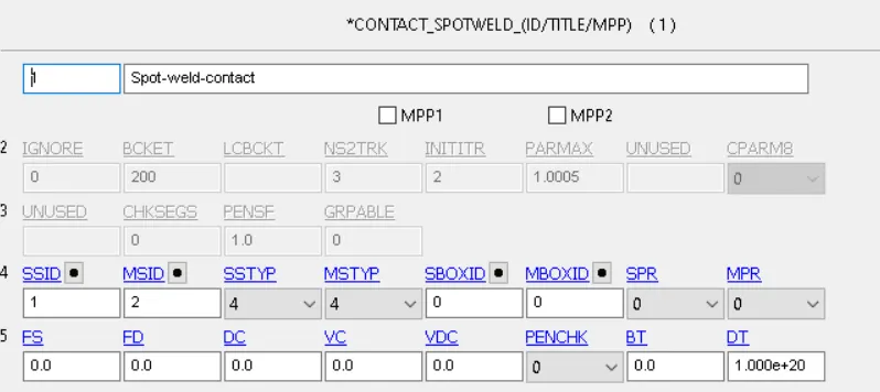
The final step to prepare our spot welds is to assign contacts between the beam elements and the sheet metal components. For that, we need to group them in two different node sets that will define the slave (spot weld nodes) and master (sheet metal components) interactions later on the contact definition.
We must also include an automatic single surface contact to avoid self penetration of the sheet metal components after impact due to high rates of yielding.

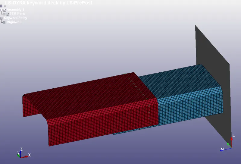
Once our spot welds are ready, we can proceed to create the rigid wall which will collide against the sheet metal components. To do so, we have to use the Create Entity Menu --> Rigidwall --> Create --> Flat (1n+NL)
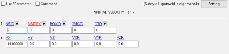
Then, we can proceed to assign the initial velocity to the component and specify our outputs before running the simulation. This has to be done using the *Initial_Velocity keyword and the previous node set of the sheet metal components
The final step before running our first simulation is to include the Hourglass energy controls, the control termination card and specifying the outputs as D3PLOT and ASCII files
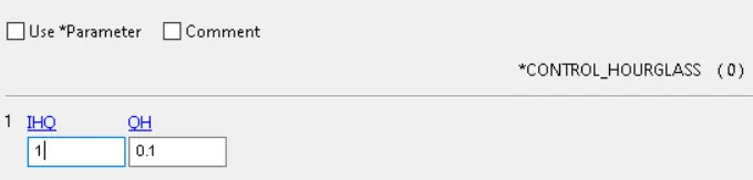


In terms of the ASCII options, we will go with:
- GLSTAT ---> Energy summary of the simulation
- MATSUM --> Specific material energy
- RCFORC ---> Resultant internal and contact forces
- SWFORC ---> Spot weld resultant forces
- RWFORC ---> Rigid wall forces
- SLEOUT --> Sliding energy output
From there we can proceed to run the simulation.
Simulation Results
The first step into post-processing of any explicit simulation is to check the energy balance. The expected kinetic energy released from the impact can be calculated as:

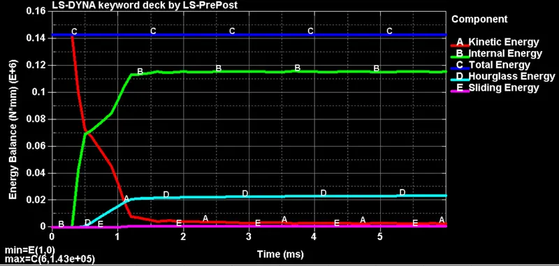
It can be observed from the previous figure that the total energy remains constant and is equal to the predicted kinetic energy before impact. It can also be observed that all this kinetic energy gets converted into internal, sliding and hourglass energy, in particular, the last one is slightly higher than the 10% threshold. This can be reduced by increasing the hourglass controls, increasing the number of integration points or by refining the mesh.
The stress contour generated during the simulation can be observed in the following video:
It can be observed that after impact the bottom component undergoes some plastic deformation, and the remaining energy gets transmitted to the upper component trough the spot welds, therefore they suffer the highest stresses.
By using the data from the SWFORC ASCII file we can obtain both the axial and shear forces developed in the spot welds, and use this information to refine out model
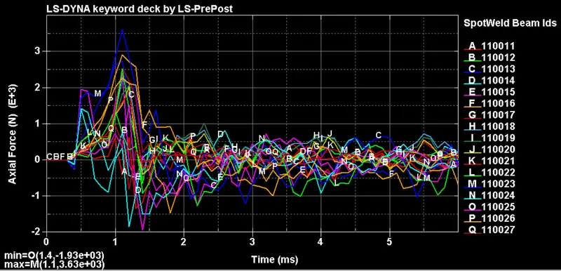
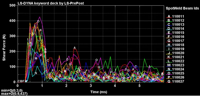
From the previous figures it can be observed that because of the position of the welds they suffer from different ratios of Axial/Shear force, but generally speaking, the axial forces developed in the welds are 90% higher in all cases, and the maximum value of this force is equal to 3630 N. Therefore, we will use this value to adjust our failure criteria for the spot weld material.
In order to simulate failure of the welds after impact, we will choose a maximum shear and axial force of 2000N
Stress contour
This modified version of the spot welds fails after impact, and therefore the upper sheet metal component collides against the lower one before sliding in the direction of the velocity.
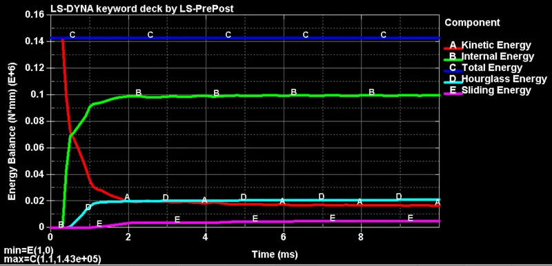
By looking at the energy balance, we can observe how a 10% of the total kinetic energy is available, thus, by increasing the simulation time we could observe how the upper component collides against the wall and dissipates this energy by elastic/plastic deformations
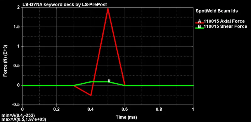
By plotting both the axial and shear forces of any of the welds we can observe how they reach the specified 2,000 N criteria slightly after impact
Case II)
Spot weld generation using Hexa-elements
The previous simulation will be repeated by replacing the beam elements for Hexa-elements in the same position. The steps that will differ from the previous case are:
- Create solid Hexa-elements by using Mesh --> Element Editing --> Hexa --> Create Hexa Element
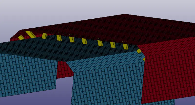
- Create a section card (Element Formulation 1 has to be used)
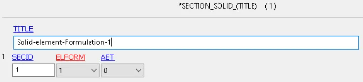
- Assign the section card and material to the Hexa-elements
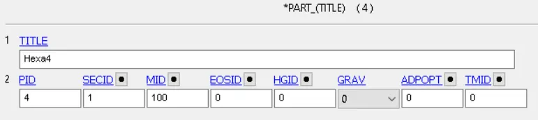
- Define a Node Set of that contains all the solid elements and replace them in the contact definition
Once all these changes have been applied, we can proceed to re-run the simulation.
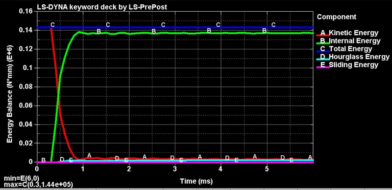
Once again, by looking at the energy balance we can observe that all the kinetic energy was successfully converted into internal, sliding and hourglass energy, yet, by using Hexa elements (which have higher number of integration points) the hourglass energy was kept very low
Stress contour
The stress contour presents a very similar behavior, a large portion of the kinetic energy is dissipated by the plastic deformation of the lower component and the rests gets transmitted through the welds, which also present some degree of plastic deformation.
Yet, a very big difference can be observed in the axial and shear forces developed in the spot welds. This was to be expected, since CBEAM elements follow the beam theory, which works best for high aspect ratio (slender) beams, and are very ineffective at capturing shear stress behavior
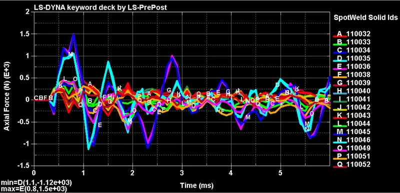
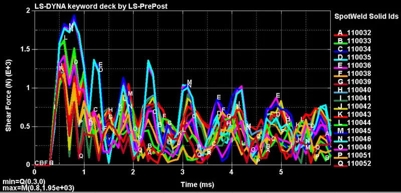
It can be observed that the axial forces in the model reached much lower values compared to the CBEAM representation, meanwhile, the shear forces increase their magnitude almost 5 times. Therefore, showing that CBEAM elements are only suitable if shear stresses are not expected to be developed during operating conditions.
If, we apply the same failure criteria as in the previous case, the spot weld that is modeled as a solid element will fail earlier in the model
Conclusions
- CBEAM elements can be used as a simplified 1D representation of spot welds, yet, they fail to accurately capture the effect of shear forces and large deflections
- Hexa elements provide a much accurate representation of weld spots, yet, they will require more nodes and therefore become computationally more demanding