Side crash analysis of Neon car BIW model in Hypermesh
Objective: To perform side crash analysis of Neon car BIW model in Hypermesh using Radioss
Model and test scenario:
The model is a reduced BIW frame of Neon car, which we have to use for the simulation.
The simulation is a side crash analysis, where the rigid object is a pole of diameter 254mm. This simulation will help us study the structural integrity and capability of the model to withstand a side crash and minimise the damage to the inner space and passengers.
Of special note are the cross members at the bottom of the BIW, which will try to absorb the impact force.
The model weight and COG needs to be balanced and the COG needs to be approximately in the same region as that of the reference model.
The boundary conditions like rigid pole, initial velocity are to be applied. The model will crash sideways into the pole
The effects of the impact are to be studied on the cross member, B pillar, hinge pillar, fuel tank and door.
Procedure:
A. Preparing the model for the simulation run
1. Import the model in Hyperworks in the Radioss module
2. We will be using the kg KN mm ms unit system for this assignment
3. Check for any initial penetrations in the model, and correct them by manual editing of the mesh.
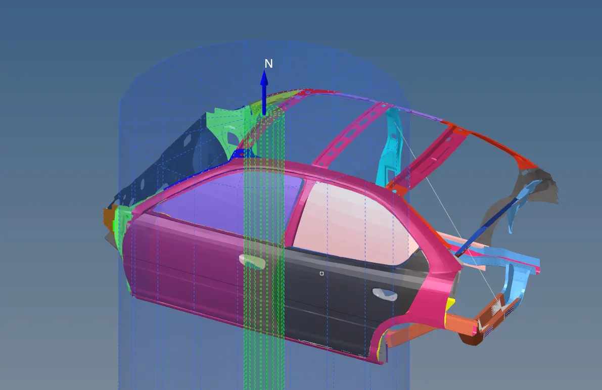
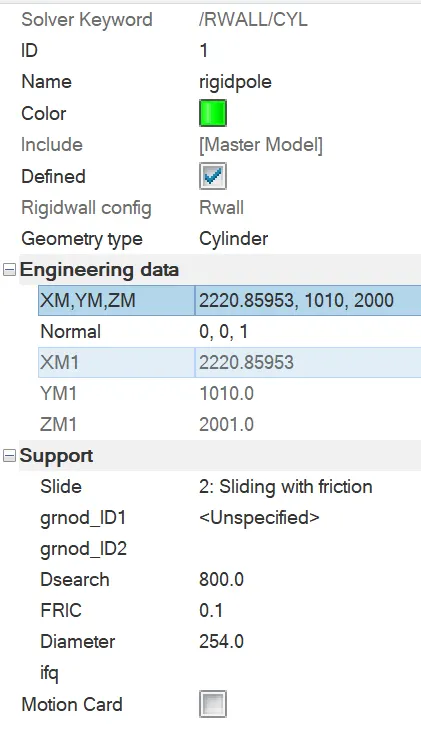
4. Now we create a rigid pole of diameter 254 mm as shown:
5. Now we check the mass details and location of COG of the model in Hypercrash:
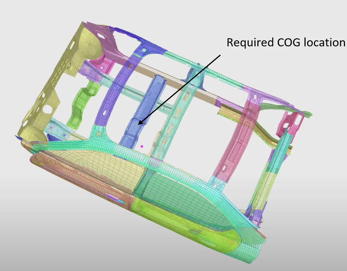
The mass of the model is 166 kg
We need to maintain 700 kg and bring the COG to under the cross member shown above.
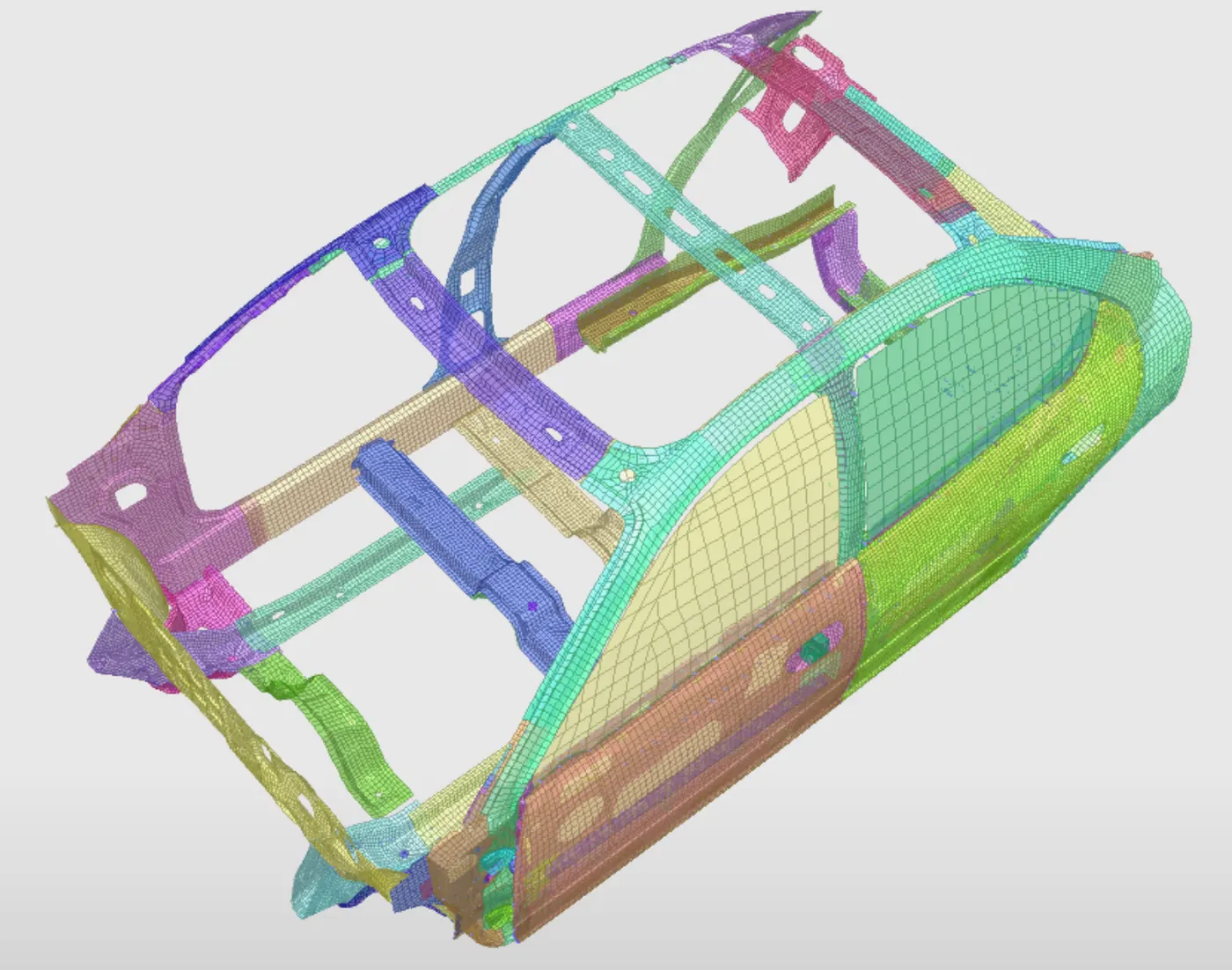
We will add masses to the dash wall and the Front seats in order to do that.
After adjusting the masses we get the CG under the cross member as shown:
6. Next we delete the existing interfaces, as they are for the subassembly components. We will create a new interface using all the nodes and elements from the model.
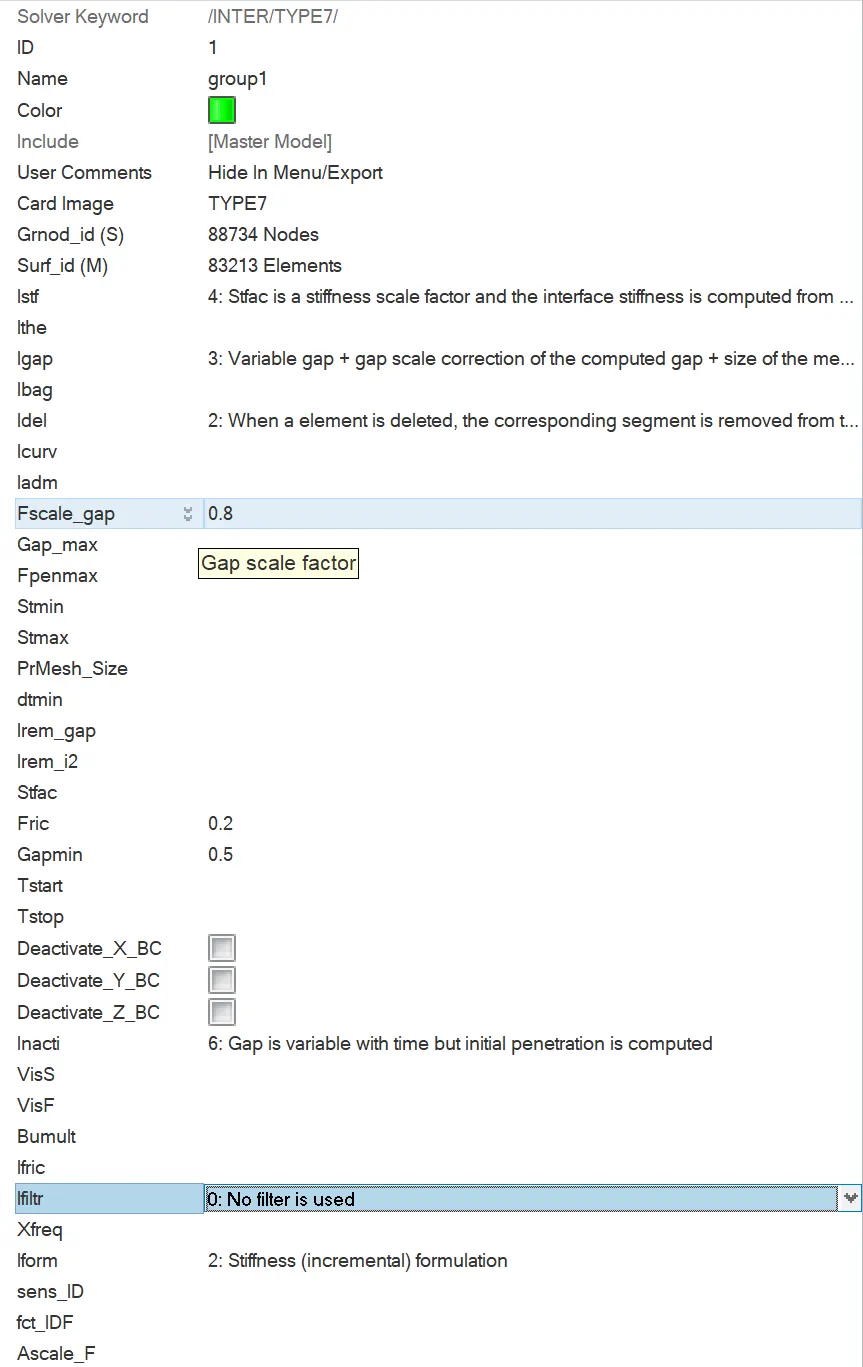
We choose Type 7 as its the best compromise between speed and accuracy of the simulation.
We use following parameters for the interface:
7. Now we create TH of nodes at the following locations:
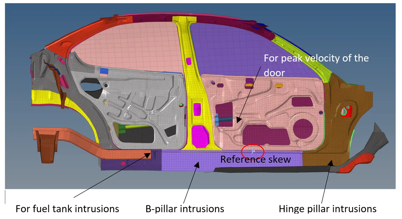
We will use the same moving skew for all the 4 TH requests, as we are interested in the Y direction magnitudes of the results.
8. We will create a DT/SHELL card with following values defined:
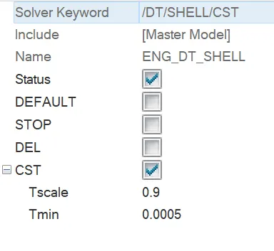
We are using 0.0005 ms as the DT because we can see that the minimum elemental time step for the model is about 0.0002 ms, from the Tools-Check elems panel:

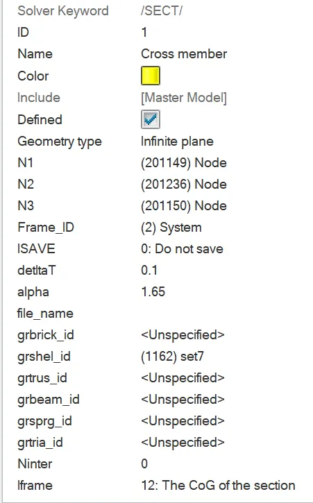
9. To study the forces generated in the cross member, we will create a section in the flat region as shown:
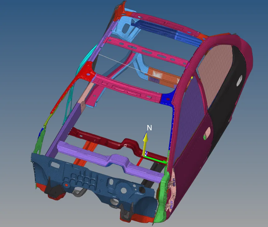
The section properties are as follows:
We will create a TH of this section so we can plot the forces generated in it.
10. Now we will run the model checker and check for any errors. After resolving any errors, we can proceed to run the simulation
B. Running the simulation
The simulation is run and the energy and mass errors are constantly monitored. Any abrupt increase in either values indicates abnormalities in the simulation, and will require debugging.
C. Plotting the results
1. After the simulation is run, we will check the Engine output file for the energy and mass errors

There is no abnormal fluctuation of either, and both are within allowable limits.
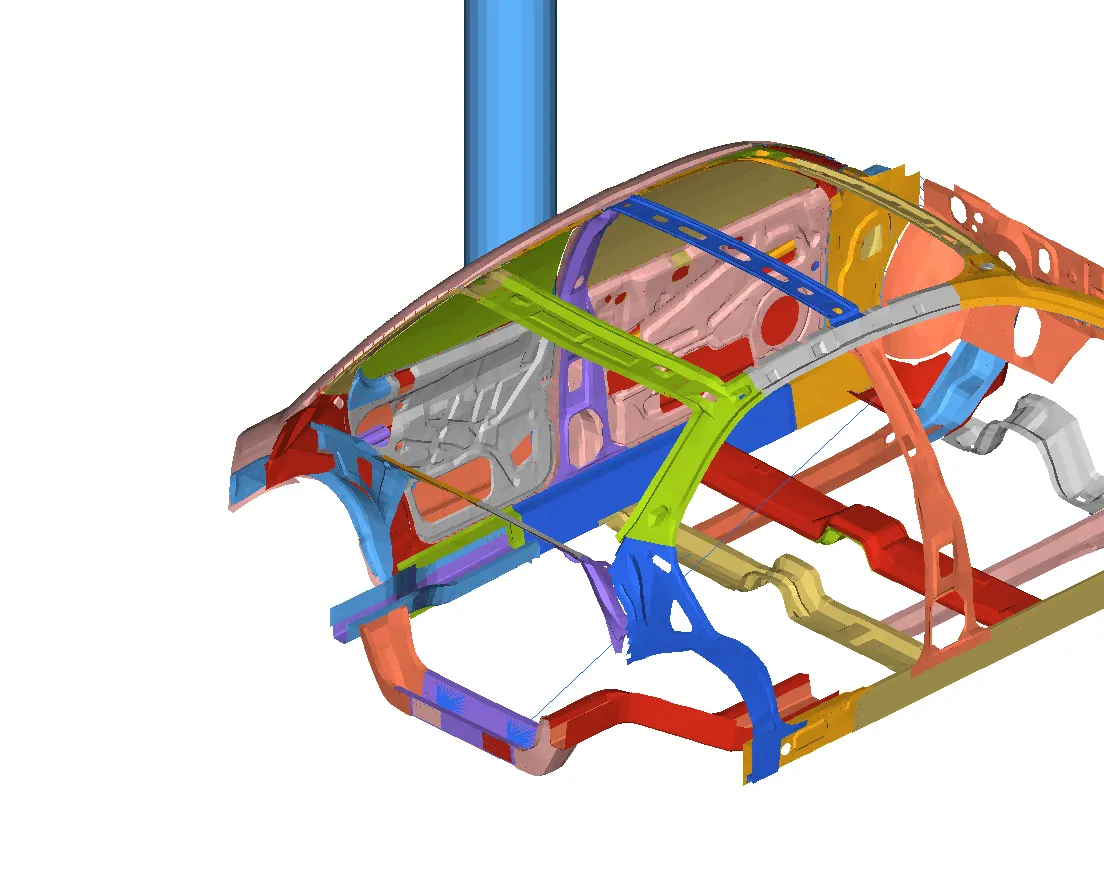
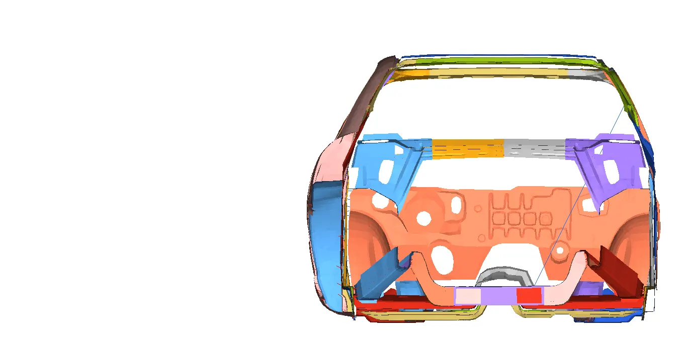
2. Now we will check the animation.
3. Von Mises Stress:
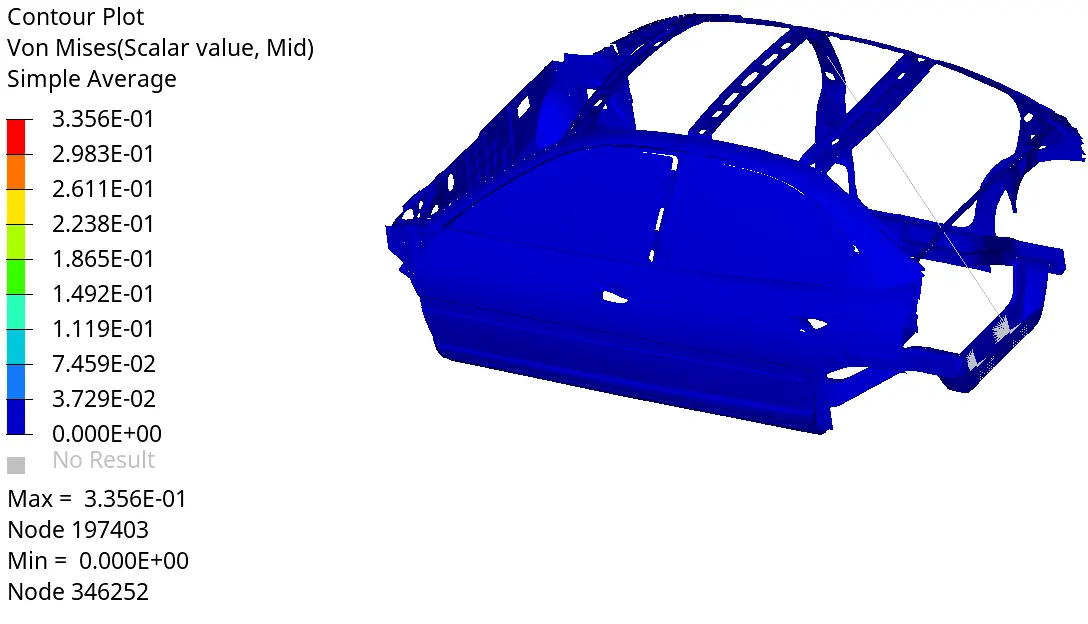
The maximum Von Mises stress is 0.3356 kN/mm2
4. We create a "distance between" curve for checking the intrusions on the B-pillar. The nodes used are as shown below:
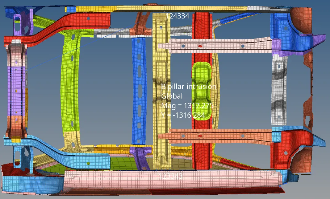
The curve for the intrusions is as shown below
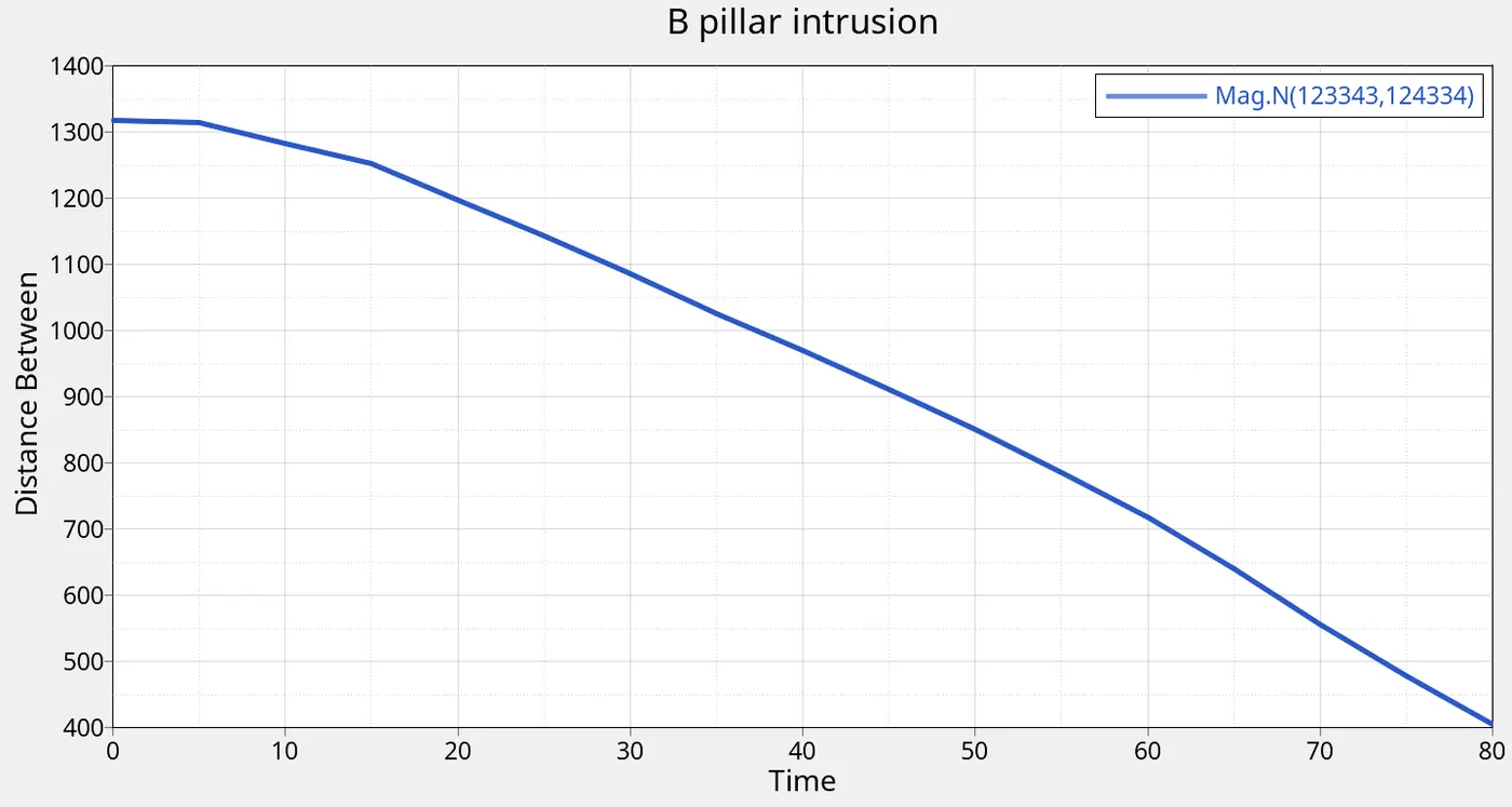
The intrusions are obtained by the max and min values of the distance, which comes out to 912.6mm
Similarly we plot the curves for the Hinge pillar and the fuel tank intrusions:
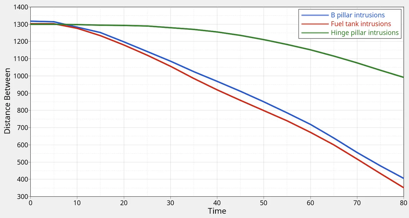
Fuel tank intrusions: 951.6 mm
Hinge pillar intrusions: 308.3 mm
We note that the intrusions on the Fuel tank are higher than the B-pillar, which is due to the lack of structural stiffening cross member at the location of the Fuel tank:
The following animation clearly demonstrates this.
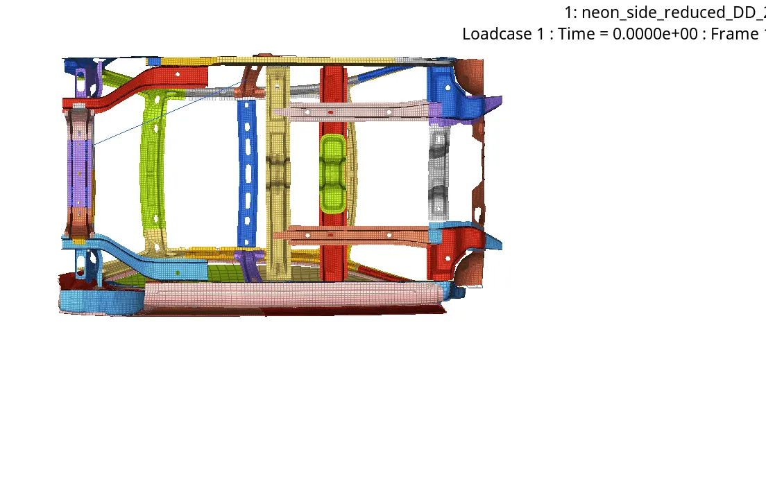
To reduce the intrusions at the fuel tank region, we can add additional cross members in the location shown below:
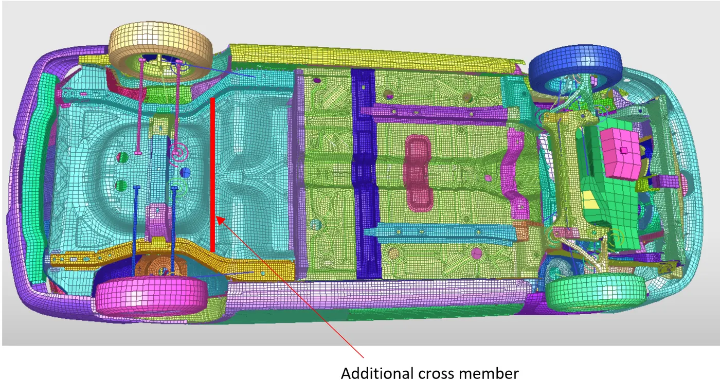
In addition to this, we can use a higher grade material like DIN1 1.4301 steel for the cross member at the fuel tank location. Higher cost of the material is justified due to its better collision sustaining capability.
5. Sectional forces generated in the cross member:
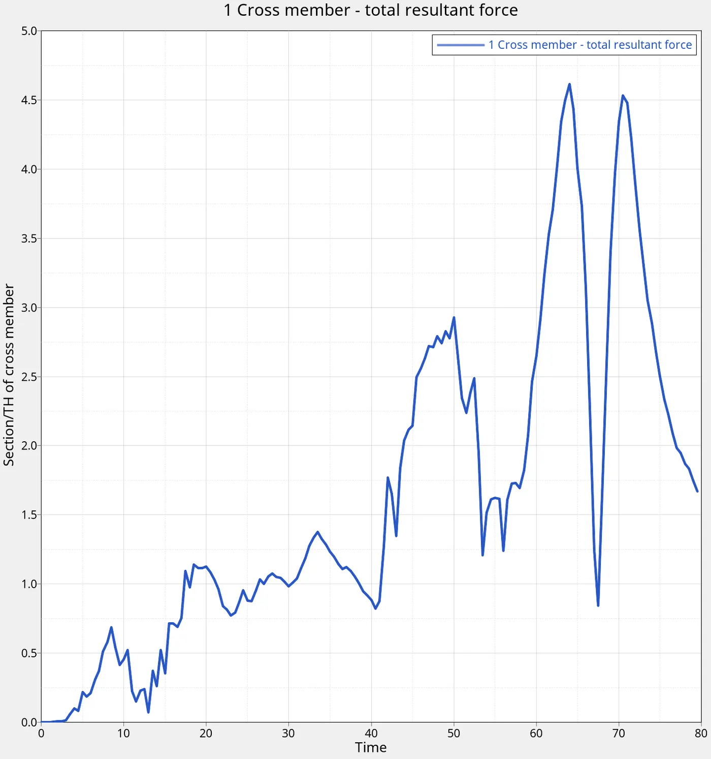
We see that the forces peak at 4.6 kN. The average force during the simulation comes out to about 1.6kN.
6. Peak velocity of inner node of door:
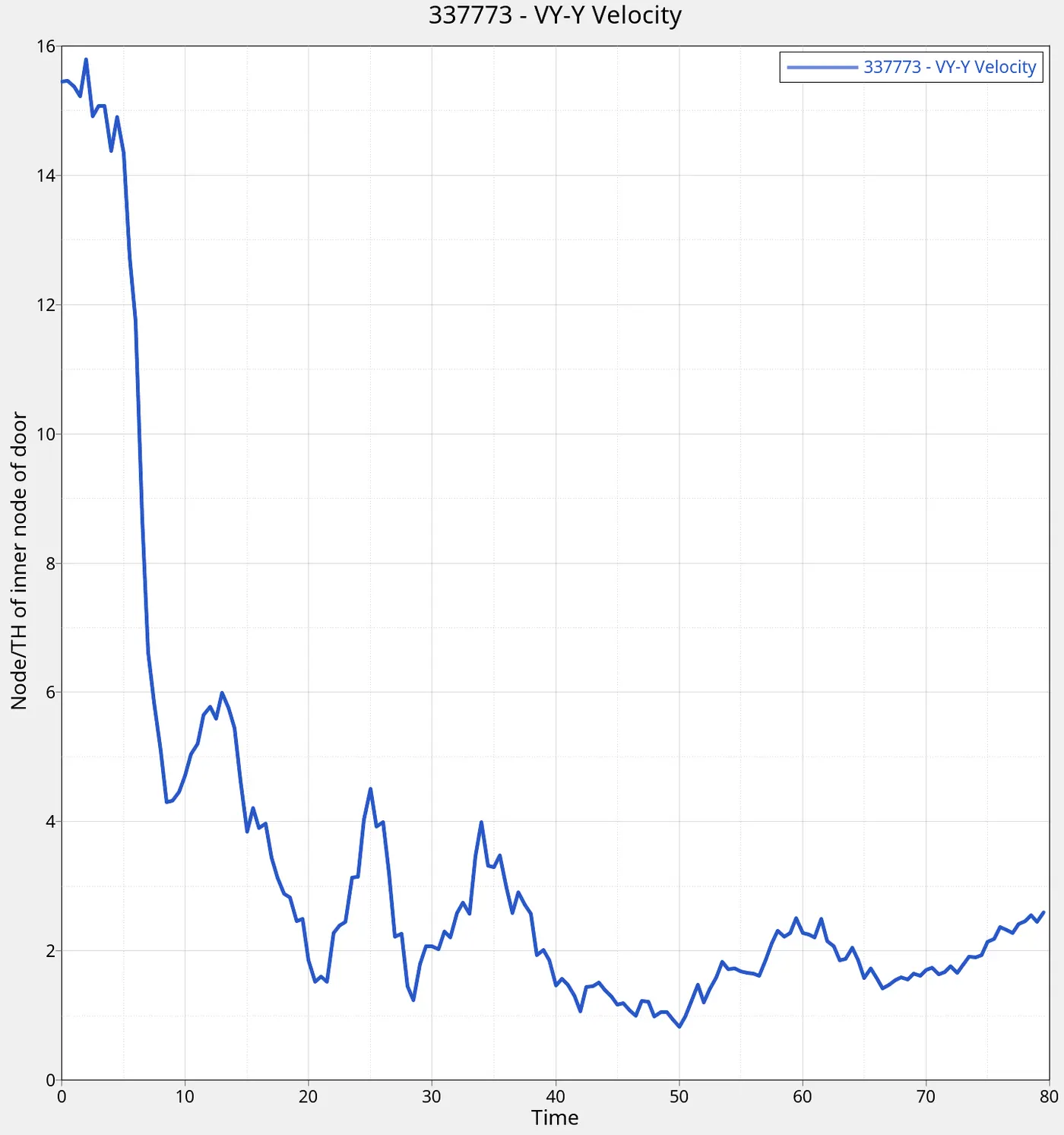
The velocity starts off at 15.6mm/ms, which is the INIVEL value we assigned to the model. After the collision, it drops steeplyto about 4.3 mm/ms and then keeps fluctuating around that value
These fluctuations are due to the structural vibrations induced in the door due to the impact.
The peak velocity post the impact is about 6mm/ms
The velocity remains positive as the door slides around the pole and coninues positive Y movement.
7. Energy graphs:
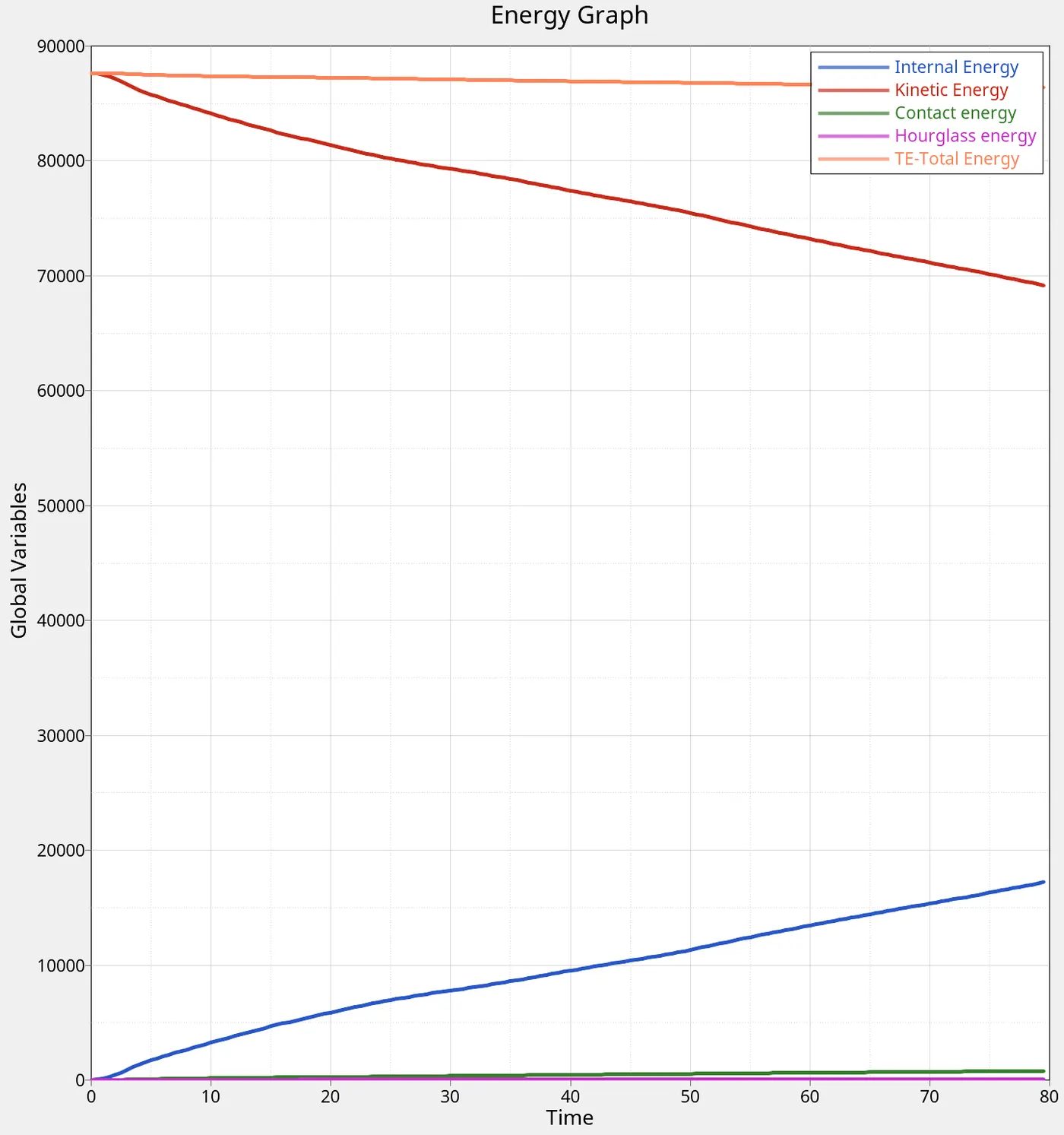
The total energy is 87650.7 Joules.
Due to the crash, the KE keeps decreasing from its initial value and the IE keeps increasing as work is done on the model in the form of deformation.
At the end of 80 ms, the body is still in motion as the KE isnt 0.
The contact energy and Hourglass energy is a small fraction of the total energy, as is confirmed from the small Energy Error of -1.0%.
CONCLUSION
1. The side crash of the Neon car BIW has been successfully carried out within acceptable limits of energy and mass errors.
2. The Intrusions on the model are :
B-pillar - 912.6mm
Fuel tank - 951.6mm
Hinge pillar - 308.3 mm
3. The velocity of the door keeps fluctuating due to the structural vibration. The peak velocity after the crash is 6mm/ms. The door slides past the pole and continues moving in the positive Y direction.
4. The section force in the cross member is peak 4.6kN and mean 1.6kN